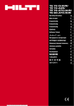
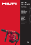
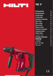
1
ORIGINAL OPERATING INSTRUCTIONS
TE 70-D/AVR rotary hammer
TE 70-AVR, TE 70-ATC/AVR, TE 80-ATC/AVR combihammer
en
It is essential that the operating instructions
are read before the power tool is operated for
the first time.
In these operating instructions, the designation “the
power tool” always refers to the TE 70-D/AVR rotary hammer or TE 70-AVR, TE 70-ATC/AVR or TE 80-ATC/AVR
combihammer.
Always keep these operating instructions together with the power tool.
TE 70-ATC/AVR and TE 80-ATC/AVR 1
Ensure that the operating instructions are
with the power tool when it is given to other
persons.
Contents
1 General information
2 Description
3 Insert tools, accessories
4 Technical data
5 Safety instructions
6 Before use
7 Operation
8 Care and maintenance
9 Troubleshooting
10 Disposal
11 Manufacturer’s warranty - tools
12 EC declaration of conformity (original)
Page
1
2
4
4
6
8
8
10
11
12
12
12
1 These numbers refer to the corresponding illustrations. The illustrations can be found on the fold-out cover
pages. Keep these pages open while studying the operating instructions.
@ Function selector switch
; Control switch lock
= Control switch
% Supply cord
& Button for 50% power reduction (only ATC combihammers)
( Side handle
) Chuck
+ Dust shield
§ Insert tool unlocking device
/ Service indicator
: Reduced-power indicator (only ATC combihammers)
TE 70-D/AVR and TE 70/AVR 2
@ Function selector switch (only combihammers)
; Control switch lock (only combihammers)
= Control switch
% Supply cord
( Side handle
) Chuck
+ Dust shield
§ Insert tool unlocking device
/ Service indicator
1 General information
1.1 Safety notices and their meaning
DANGER
Draws attention to imminent danger that will lead to
serious bodily injury or fatality.
WARNING
Draws attention to a potentially dangerous situation that
could lead to serious personal injury or fatality.
CAUTION
Draws attention to a potentially dangerous situation that
could lead to slight personal injury or damage to the
equipment or other property.
NOTE
Draws attention to an instruction or other useful information.
1.2 Explanation of the pictograms and other
information
Warning signs
General
warning
Warning:
electricity
Warning: hot
surface
1
Printed: 16.05.2014 | Doc-Nr: PUB / 5150803 / 000 / 01
Obligation signs
Wear eye
protection
en
Wear a hard
hat
Wear ear
protection
Wear
protective
gloves
Wear
breathing
protection
Diameter
Chiseling
Chisel
position
adjustment
Double
insulated
Hammer
drilling
Location of identification data on the power tool
The type designation and serial number can be found
on the type identification plate on the machine or tool.
Make a note of this data in your operating instructions
and always refer to it when making an enquiry to your
Hilti representative or service department.
Symbols
Read the
operating
instructions
before use
Revolutions
per minute
Returning
materials for
recycling
Volts
Amps
Type:
Generation: 03
Serial no.:
Watts
Alternating
current
Hertz
Rated speed
under no
load
2 Description
2.1 Use of the product as directed
The power tool is an electrically-powered rotary hammer (TE 70-D/AVR) or combihammer with pneumatic hammering
mechanism. The ATC (Active Torque Control) function incorporated in the TE 70‑ATC/AVR and TE 80‑ATC/AVR
provides greater operating comfort while drilling
The power tool is designed for drilling in concrete, masonry, metal and wood and can also be used for chiseling (not
the TE 70-D/AVR).
The power tool may be used to work only on non-flammable materials.
Under certain conditions, the power tool is suitable for use for mixing (see “Tools, accessories” and “Operation”).
Working on materials hazardous to the health (e.g. asbestos) is not permissible.
Observe national health and safety requirements.
The power tool is designed for professional use and may be operated, serviced and maintained only by trained,
authorized personnel. This personnel must be informed of any special hazards that may be encountered. The power
tool and its ancillary equipment may present hazards when used incorrectly by untrained personnel or when used not
as directed.
The working environment may be as follows: construction site, workshop, renovation, conversion or new construction.
The power tool may be used only in a dry environment.
Do not use the power tool where there is a risk of fire or explosion.
The power tool may be operated only when connected to a power supply providing a voltage and frequency in
compliance with the information given on its type identification plate.
Modification of the power tool or tampering with its parts is not permissible.
To avoid the risk of injury, use only genuine Hilti accessories and insert tools.
Observe the information printed in the operating instructions concerning operation, care and maintenance.
2
Printed: 16.05.2014 | Doc-Nr: PUB / 5150803 / 000 / 01
2.2 Chuck
TE‑Y (SDS max) quick-change “click” chuck
2.3 Switches
Speed control switch for smooth starting
Combihammer function selector switch: Hammer drilling, chiseling, chisel adjustment (24 positions – depends on
version)
Selector for full or reduced (50%) power (depends on version)
Control switch locking mechanism which can be locked for chiseling (depends on version)
2.4 Grips
Vibration-absorbing, pivotable side handle
Vibration-absorbing grip
2.5 Protective devices
Mechanical safety clutch
Electronic restart interlock to prevent the power tool starting unintentionally after an interruption in the electric supply
(see section 9 “Troubleshooting”).
Additional ATC “Active Torque Control” (TE 70‑ATC/AVR and TE 80‑ATC/AVR)
2.6 Lubrication
Gearing and hammering mechanism with separate lubrication chambers
2.7 Active Vibration Reduction
The tool is equipped with the “Active Vibration Reduction” (AVR) system, which significantly reduces vibration.
TE 80-ATC/AVR also has a handle damping system.
2.8 LED indicators
Service indicator LED (see section “Care and maintenance”)
Reduced-power indicator (depends on version): (Please refer to the “Operation” section.)
2.9 Items supplied
1
Power tool
1
Grease
1
1
1
1
Side handle
Cleaning cloth
Operating instructions
Hilti toolbox
2.10 Using extension cords
Recommended minimum conductor cross section and max. cable lengths
Conductor cross section
1.5 mm²
Mains voltage 100V
2.0 mm²
2.5 mm²
30 m
Mains voltage 110-127 V
20 m
Mains voltage 220-240 V
30 m
30 m
3.5 mm²
50 m
40 m
75 m
2.11 Using a generator or transformer
This power tool may be powered by a generator or transformer when the following conditions are fulfilled: The unit
must provide a power output in watts of at least twice the value printed on the type identification plate on the power
tool. The operating voltage must remain within +5% and -15% of the rated voltage at all times, frequency must be in
the 50 – 60 Hz range and never above 65 Hz, and the unit must be equipped with automatic voltage regulation and
starting boost.
3
Printed: 16.05.2014 | Doc-Nr: PUB / 5150803 / 000 / 01
en
Never operate other power tools or appliances from the generator or transformer at the same time. Switching other
power tools or appliances on and off may cause undervoltage and / or overvoltage peaks, resulting in damage to the
power tool.
en
3 Insert tools, accessories
Insert tools
Designation
Description
Hammer drill bits
∅ 12…45 mm
Breach bits
∅ 40…80 mm
Percussion core bits
∅ 45…150 mm
PCM diamond core bits
∅ 42…132 mm
Chisels
Wood drill bits
Pointed, flat and shaped chisels with TE‑Y connection
end
∅ 10…32 mm
Metal drill bits
Up to ∅ 20 mm
Depth gauge
TE-FY-BA-C adapter
TE-Y-AD adapter
Dust modules TE DRS-BK,TE DRS-B, TE DRS-S
Accessories
Designation
Item number, description
Setting tool
32221, Setting tool with TE‑Y connection end
Quick-release chuck
60208, Keyless chuck for wood and metal drill bits with
smooth or hex. shank, Chuck holder 263359
41215 (∅80mm), 41216 (∅110mm), ∅ 80…150 mm, For
use only with the keyless quick-release chuck
Mixing paddles,with smooth or hex. shank, for mixing
non-flammable, non-hazardous substances
4 Technical data
Right of technical changes reserved.
Power tool
TE 70-D/AVR
TE 70‑AVR
TE 70-ATC/AVR
TE 80-ATC/AVR
Weight in accordance with EPTA
procedure 01/2003
Dimensions (L ×
W × H)
8.3 kg
8.3 kg
9.5 kg
9.7 kg
536 mm ×
126 mm ×
305.5 mm
536 mm ×
126 mm ×
305.5 mm
536 mm ×
126 mm × 324 mm
549 mm ×
126 mm × 324 mm
NOTE
The power tool is available in various voltage ratings. Please refer to the type identification plate for details of the
power tool’s voltage and power rating.
Power tool
TE 70-D/AVR
TE 70‑AVR
TE 70-ATC/AVR
TE 80-ATC/AVR
Rated power input
1,800 W
1,800 W
1,800 W
1,800 W
4
Printed: 16.05.2014 | Doc-Nr: PUB / 5150803 / 000 / 01
Power tool
TE 70-D/AVR
TE 70‑AVR
TE 70-ATC/AVR
TE 80-ATC/AVR
Rated current input
Rated voltage
100 V: 15 A
Rated voltage 120:
15 A
Rated voltage
220 V: 9.9 A
Rated voltage
230 V: 9.9 A
Rated voltage
100 V: 15 A
Rated voltage
110 V: 16 A
Rated voltage
(Taiwan) 110 V: 15 A
Rated voltage 120:
15 A
Rated voltage
220 V: 9.9 A
Rated voltage
230 V: 9.9 A
Rated voltage
240 V: 9.8 A
50…60 Hz
Rated voltage
110 V: 16 A
Rated voltage 120:
15 A
Rated voltage
220 V: 9.9 A
Rated voltage
230 V: 9.9 A
50…60 Hz
Mains frequency
50…60 Hz
Rated voltage
100 V: 15 A
Rated voltage
110 V: 16 A
Rated voltage
(Taiwan) 110 V: 15 A
Rated voltage 120:
15 A
Rated voltage
220 V: 9.9 A
Rated voltage
230 V: 9.9 A
Rated voltage
240 V: 9.8 A
50…60 Hz
Hammer drilling
speed
Single impact energy in accordance
with EPTA procedure 05/2009 (full
power setting)
360/min
360/min
360/min
360/min
11.5 J
11.5 J
11.5 J
11.5 J
en
NOTE
The TE 70‑ATC/AVR and TE 80‑ATC/AVR comply with the applicable standard on condition that the maximum
permitted supply network impedance Zmaxmax is less than or equal to 0.342+j0.25 Ω at the point at which the
user's supply network is connected to the public supply network. It is the responsibility of the installer or user of the
equipment to ensure, by consultation with the supply network operator if necessary, that the equipment is connected
only at a point in the supply with an impedance of less than or equal to Zmax.
Other information about the power tool
ATC electronic cut-out
TE 70‑ATC/AVR, TE 80‑ATC/AVR
Protection class
Protection class II (double insulated)
NOTE
Noise and vibration information (measured as per EN 60745-2-6): The triaxial vibration value given in this information
sheet has been measured in accordance with a standardized test given in EN 60745 and may be used to compare one
electric tool with another. It may be used for a preliminary assessment of exposure. The declared vibration emission
level represents the main applications of the tool. However, if the tool is used for different applications, with different
accessories or poorly maintained, the vibration emission may differ. This may significantly increase the exposure level
over the total working period. An estimation of the level of exposure to vibration should also take into account the
times when the tool is switched off or when it is running but not actually doing the job. This may significantly reduce
the exposure level over the total working period. Identify additional safety measures to protect the operator from the
effects of vibration such as: Maintaining the machine and insert tools, keeping the hands warm and organizing work
patterns.
Power tool
TE 70-D/AVR
TE 70‑AVR
TE 70-ATC/AVR
TE 80-ATC/AVR
Typical A-weighted
sound power level
Typical A-weighted
emission sound
pressure level
Uncertainty for the
given sound level
Hammer drilling in
concrete, ah, HD
113 dB (A)
113 dB (A)
113 dB (A)
113 dB (A)
102 dB (A)
102 dB (A)
102 dB (A)
102 dB (A)
3 dB (A)
3 dB (A)
3 dB (A)
3 dB (A)
10 m/s²
10 m/s²
10 m/s²
7.5 m/s²
9 m/s²
9 m/s²
7 m/s²
Chiseling, ah, Cheq
5
Printed: 16.05.2014 | Doc-Nr: PUB / 5150803 / 000 / 01
en
Power tool
TE 70-D/AVR
TE 70‑AVR
TE 70-ATC/AVR
TE 80-ATC/AVR
Uncertainty (K) for
triaxial vibration values
1.5 m/s²
1.5 m/s²
1.5 m/s²
1.5 m/s²
5 Safety instructions
5.1 General Power Tool Safety Warnings
a)
WARNING
Read all safety warnings and all instructions. Failure to follow the warnings and instructions may result
in electric shock, fire and/or serious injury. Save all
warnings and instructions for future reference.
The term “power tool” in the warnings refers to
your mains-operated (corded) power tool or batteryoperated (cordless) power tool.
5.1.1 Work area safety
Keep work area clean and well lit. Cluttered or dark
areas invite accidents.
b) Do not operate power tools in explosive atmospheres, such as in the presence of flammable
liquids, gases or dust. Power tools create sparks
which may ignite the dust or fumes.
c) Keep children and bystanders away while operating a power tool. Distractions can cause you to lose
control.
a)
5.1.2 Electrical safety
Power tool plugs must match the outlet. Never
modify the plug in any way. Do not use any adapter plugs with earthed (grounded) power tools.
Unmodified plugs and matching outlets will reduce
risk of electric shock.
b) Avoid body contact with earthed or grounded
surfaces, such as pipes, radiators, ranges and
refrigerators. There is an increased risk of electric
shock if your body is earthed or grounded.
c) Do not expose power tools to rain or wet conditions. Water entering a power tool will increase the
risk of electric shock.
d) Do not abuse the cord. Never use the cord for
carrying, pulling or unplugging the power tool.
Keep cord away from heat, oil, sharp edges or
moving parts. Damaged or entangled cords increase
the risk of electric shock.
e) When operating a power tool outdoors, use an
extension cord suitable for outdoor use. Use of
a cord suitable for outdoor use reduces the risk of
electric shock.
f) If operating a power tool in a damp location is
unavoidable, use a residual current device (RCD)
protected supply. Use of an RCD reduces the risk
of electric shock.
a)
5.1.3 Personal safety
a)
Stay alert, watch what you are doing and use
common sense when operating a power tool. Do
6
Printed: 16.05.2014 | Doc-Nr: PUB / 5150803 / 000 / 01
not use a power tool while you are tired or under
the influence of drugs, alcohol or medication. A
moment of inattention while operating power tools
may result in serious personal injury.
b) Use personal protective equipment. Always wear
eye protection. Protective equipment such as dust
mask, non-skid safety shoes, hard hat, or hearing
protection used for appropriate conditions will reduce
personal injuries.
c) Prevent unintentional starting. Ensure the switch
is in the off‐position before connecting to power
source and/or battery pack, picking up or carrying
the tool. Carrying power tools with your finger on the
switch or energising power tools that have the switch
on invites accidents.
d) Remove any adjusting key or wrench before turning the power tool on. A wrench or a key left attached to a rotating part of the power tool may result
in personal injury.
e) Do not overreach. Keep proper footing and balance at all times. This enables better control of the
power tool in unexpected situations.
f) Dress properly. Do not wear loose clothing or
jewellery. Keep your hair, clothing and gloves
away from moving parts. Loose clothes, jewellery
or long hair can be caught in moving parts.
g) If devices are provided for the connection of dust
extraction and collection facilities, ensure these
are connected and properly used. Use of dust
collection can reduce dust-related hazards.
5.1.4 Power tool use and care
Do not force the power tool. Use the correct
power tool for your application. The correct power
tool will do the job better and safer at the rate for
which it was designed.
b) Do not use the power tool if the switch does not
turn it on and off. Any power tool that cannot be
controlled with the switch is dangerous and must be
repaired.
c) Disconnect the plug from the power source
and/or the battery pack from the power tool
before making any adjustments, changing
accessories, or storing power tools. Such
preventive safety measures reduce the risk of
starting the power tool accidentally.
d) Store idle power tools out of the reach of children and do not allow persons unfamiliar with the
power tool or these instructions to operate the
power tool. Power tools are dangerous in the hands
of untrained users.
a)
Maintain power tools. Check for misalignment or
binding of moving parts, breakage of parts and
any other condition that may affect the power
tool’s operation. If damaged, have the power tool
repaired before use. Many accidents are caused by
poorly maintained power tools.
f) Keep cutting tools sharp and clean. Properly maintained cutting tools with sharp cutting edges are less
likely to bind and are easier to control.
g) Use the power tool, accessories and tool bits etc.
in accordance with these instructions, taking into
account the working conditions and the work to
be performed. Use of the power tool for operations different from those intended could result in a
hazardous situation.
e)
5.1.5 Service
a)
Have your power tool serviced by a qualified repair
person using only identical replacement parts.
This will ensure that the safety of the power tool is
maintained.
5.2 Hammer safety warnings
Wear ear protectors. Exposure to noise can cause
hearing loss.
b) Use auxiliary handles, if supplied with the tool.
Loss of control can cause personal injury.
c) Hold power tool by insulated gripping surfaces,
when performing an operation where the cutting
accessory may contact hidden wiring or its own
cord. Cutting accessory contacting a "live" wire may
make exposed metal parts of the power tool "live"
and could give the operator an electric shock.
a)
5.3 Additional safety instructions
5.3.1 Personal safety
Always hold the power tool securely with both
hands on the grips provided. Keep the grips dry,
clean and free from oil and grease.
b) Breathing protection must be worn if the power
tool is used without a dust removal system for
work that creates dust.
c) Improve the blood circulation in your fingers by
relaxing your hands and exercising your fingers
during breaks between working.
d) Avoid touching rotating parts. Switch the power
tool on only after bringing it into position at the
workpiece. Touching rotating parts, especially rotating insert tools, may lead to injury.
e) Always lead the supply cord and extension cord
away from the power tool to the rear while working. This helps to avoid tripping over the cord while
working.
f) When using the power tool for mixing, set the
function selector switch to “Hammer drilling” and
wear protective gloves.
g) Children must be instructed not to play with the
power tool.
a)
h)
The power tool is not intended for use by children,
by debilitated persons or those who have received
no instruction or training.
5.3.2 Power tool use and care
Secure the workpiece. Use clamps or a vice to
secure the workpiece. The workpiece is thus held
more securely than by hand and both hands remain
free to operate the power tool.
b) Check that the insert tools used are compatible
with the chuck system and that they are secured
in the chuck correctly.
c) Always work from a secure, safe stance.
a)
5.3.3 Electrical safety
Before beginning work, check the working area
(e.g. using a metal detector) to ensure that no
concealed electric cables or gas and water pipes
are present. External metal parts of the power tool
may become live, for example, when an electric cable
is damaged accidentally. This presents a serious risk
of electric shock.
b) Check the power tool’s supply cord at regular
intervals and have it replaced by a qualified specialist if found to be damaged. If the machine’s
supply cord is damaged it must be replaced with
a specially-prepared and approved supply cord
available from Hilti Customer Service. Check extension cords at regular intervals and replace
them if found to be damaged. Do not touch the
supply cord or extension cord if it is damaged
while working. Disconnect the mains plug from
the power outlet. Damaged supply cords or extension cords present a risk of electric shock.
c) Dirty or dusty power tools which have been used
frequently for work on conductive materials
should be checked at regular intervals at a Hilti
Service Center. Under unfavorable circumstances,
dampness or dust adhering to the surface of
the power tool, especially dust from conductive
materials, may present a risk of electric shock.
d) When working outdoors with an electric tool
check to ensure that the tool is connected to the
electric supply by way of a ground fault circuit
interrupter (RCD) with a rating of max. 30 mA
(tripping current). Use of a ground fault circuit
interrupter reduces the risk of electric shock.
e) Use of a ground fault circuit interrupter (RCD
residual current device) with a maximum tripping
current of 30 mA is recommended.
a)
5.3.4 Work area
a) Ensure that the workplace is well lit.
b) Ensure that the workplace is well ventilated. Exposure to dust at a poorly ventilated workplace may
result in damage to the health.
c) Dust from material such as paint containing lead,
some wood species, minerals and metal may be
harmful. Contact with or inhalation of the dust may
7
Printed: 16.05.2014 | Doc-Nr: PUB / 5150803 / 000 / 01
en
en
cause allergic reactions and/or respiratory diseases
to the operator or bystanders. Certain kinds of dust
are classified as carcinogenic such as oak and beech
dust especially in conjunction with additives for wood
conditioning (chromate, wood preservative). Material
containing asbestos must only be treated by specialists. Where the use of a dust extraction device is
possible it shall be used. To achieve a high level
of dust collection, use a suitable vacuum cleaner
of the type recommended by Hilti for wood dust
and/or mineral dust together with this tool. Ensure
that the workplace is well ventilated. The use of a
dust mask of filter class P2 is recommended. Follow national requirements for the materials you
want to work with.
d) If the work involves breaking right through, take
the appropriate safety measures at the opposite
side. Parts breaking away could fall out and / or fall
down and injure other persons.
5.3.5 Personal protective equipment
The user and any other persons in the vicinity must
wear suitable eye protection, a hard hat, ear protection, protective gloves, safety footwear and respiratory protection while the tool is in use.
6 Before use
3.
4.
5.
6.1 Fitting and adjusting the side handle 3
1.
2.
Disconnect the mains plug from the power outlet.
Release the side handle clamping band by turning
the handle counterclockwise.
Slide the side handle clamping band over the chuck
and onto the neck of the power tool.
Pivot the side handle into the desired position.
CAUTION Check that the clamping band is engaged in the groove provided on the power tool.
Secure the side handle by turning the grip clockwise.
6.2 Use of extension cords and generators or
transformers
Please refer to section 2 “Description”.
7 Operation
7.1 Preparing for use
CAUTION
Wear protective gloves when changing insert tools as
the insert tools get hot during use.
CAUTION
In accordance with the applications for which it is designed, the power tool produces a high torque. Always
use the side handle and hold the power tool with both
hands. The user must be prepared for sudden sticking
and stalling of the insert tool.
CAUTION
Use clamps or a vice to hold the workpiece securely.
CAUTION
The collar at the front end of the gearing section is
not to be used as a gripping surface.
CAUTION
Check the insert tool for damage or uneven wear each
time before use.
8
Printed: 16.05.2014 | Doc-Nr: PUB / 5150803 / 000 / 01
7.1.1 Fitting the insert tool 4
1.
2.
3.
4.
5.
Disconnect the supply cord plug from the power
outlet.
Check that the connection end of the insert tool is
clean and lightly greased. Clean it and grease it if
necessary.
Check that the sealing lip of the dust shield is
clean and in good condition. Clean the dust shield
if necessary or have it replaced if the sealing lip is
damaged.
Push the insert tool into the chuck and rotate it while
applying slight pressure until it engages in the guide
grooves.
Push the insert tool further into the chuck until it is
heard to engage.
6.
Check that the insert tool has engaged correctly by
pulling it.
7.1.2 Removing the insert tool 5
1.
2.
3.
Disconnect the mains plug from the power outlet.
Open the chuck by pulling back the insert tool unlocking device.
Pull the insert tool out of the chuck.
7.2 Operation
5.
6.
7.
8.
Position the power tool and drill bit at the point
where the hole is to be drilled.
Press the control switch slowly (drill at a low speed
until the drill bit centers itself in the hole).
Press the control switch fully to continue working at
full power.
NOTE Do not apply excessive pressure. This will not
increase the power tool’s hammering performance.
Lower pressure extends the life of the insert tool.
Reduce drilling speed shortly before breaking
through in order to avoid spalling.
7.2.2 Active Torque Control (TE 70‑ATC/AVR and
TE 80‑ATC/AVR)
CAUTION
Working on the material may cause it to splinter. Wear
eye protection and protective gloves. Wear breathing
protection if no dust removal system is used. Splintering material presents a risk of injury to the eyes and
body.
CAUTION
The work generates noise. Wear ear protectors. Exposure to noise can cause hearing loss.
CAUTION
Switch the power tool on only after bringing it into the
working position.
CAUTION
Do not operate the function selector switch while the
motor is running.
7.2.1 Hammer drilling 6
NOTE
Working at low temperatures: The hammering mechanism works only when the power tool has reached a
minimum operating temperature. Bring the tip of the drill
bit or chisel into contact with the workpiece and allow
the power tool to run under no load until it reaches
the minimum operating temperature. If necessary, repeat
this procedure until the hammering mechanism begins to
operate.
1.
2.
3.
4.
Turn the function selector switch until it engages in
the “Hammer drilling” position.
Bring the side handle into the desired position and
check that it is fitted correctly and secured.
Plug the supply cord into the power outlet.
Set the desired drilling power (optional).
NOTE After connecting the supply cord to the electric supply, the power tool is always set to full drilling
power.
NOTE To set the power tool to reduced (50%) drilling
power (depends on version), press the reducedpower button. The reduced-power LED lights to
indicate reduced power. Press the reduced-power
button again to switch to full power. The reducedpower LED then goes out.
In addition to the mechanical safety slip clutch, the power
tool is also equipped with the Active Torque Control system. This system offers additional comfort while drilling
as it causes rapid shutdown upon sudden rotation of
the power tool about the drill bit axis, e.g. when the
drill bit sticks due to hitting a rebar or when the drill bit
is tilted unintentionally. When the torque control system
has become activated, the power tool can be restarted by
releasing the control switch and re-engaging it after the
motor has stopped rotating (a “click” indicates that the
power tool is again ready for operation). Always choose a
working position in which the electric tool is free to rotate
in a counterclockwise direction (as seen by the operator).
If this rotation is not possible, the ATC system will be
unable to react.
7.2.3 Drilling without hammering
Drilling without hammering is possible when drill bits with
a special connection end are used. Drill bits of this kind
are available from Hilti. For example, when the keyless
quick-release chuck is fitted, smooth-shank drill bits for
wood or steel can be used to drill without hammering.
The function selector switch must be set to the “Hammer
drilling” position when the power tool is used in this way.
7.2.4 Chiseling (depends on version) 7
NOTE
The chisel can be adjusted to 24 different positions
(in 15° increments). This ensures that flat chisels and
shaped chisels can always be set to the optimum working
position.
CAUTION
Do not operate the power tool when the selector switch
is set to “Chisel adjustment”.
1.
2.
3.
4.
To adjust the position of the chisel, turn the function selector switch until it engages in the “Chisel
adjustment” position.
Bring the side handle into the desired position and
check that it is fitted correctly and secured.
Rotate the chisel to the desired position.
To lock the chisel in the desired position, turn
the function selector switch until it engages in the
“Chiseling” position. Do not operate the function
selector switch while the motor is running.
9
Printed: 16.05.2014 | Doc-Nr: PUB / 5150803 / 000 / 01
en
5.
6.
en
7.
8.
To begin chiseling, plug the power tool’s supply
cord into the power outlet.
Set the desired chiseling power level (depends on
version).
NOTE After connecting the supply cord to the electric supply, the power tool is always set to full
chiseling power.
NOTE To set the power tool to reduced (50%) chiseling power (depends on version), press the reducedpower button. The reduced-power LED lights to
indicate reduced power. Press the reduced-power
button again to switch to full chiseling power. The
reduced-power LED then goes out.
Position the tip of the chisel at the point where
chiseling is to begin.
Press the control switch fully.
7.2.5 Locking the control switch (depends on
version) 8
When chiseling, the control switch can be locked in the
“on” position.
1. Push the control switch lock at the top of the grip to
the forward position.
2.
3.
Press the control switch fully.
The power tool then operates in sustained mode.
To cancel sustained operating mode, slide the control switch lock to the rear.
The power tool then switches off.
7.2.6 Mixing
1.
Turn the function selector switch until it engages in
the “Hammer drilling” position.
2. Insert the quick-release chuck in the power tool’s
chuck.
3. Insert the mixing paddle.
4. Check that the insert tool has engaged correctly by
pulling it.
5. Bring the side handle into the desired position and
check that it is fitted correctly and secured.
6. Plug the supply cord into the power outlet.
7. Position the mixing paddle in the container holding
the substance to be mixed.
8. To begin mixing, press the control switch slowly.
9. Press the control switch fully to continue working at
full power.
10. Guide the mixing paddle carefully in order to avoid
splashing and spillage.
8 Care and maintenance
CAUTION
Disconnect the mains plug from the power outlet.
8.1 Care of insert tools
Clean off dirt and dust deposits adhering to the insert
tools and protect them from corrosion by wiping the
insert tools from time to time with an oil-soaked rag.
8.2 Care of the power tool
CAUTION
Keep the power tool, especially its grip surfaces,
clean and free from oil and grease. Do not use cleaning agents which contain silicone.
Never operate the power tool when the ventilation slots
are blocked. Clean the ventilation slots carefully using
a dry brush. Do not permit foreign objects to enter the
interior of the power tool. Clean the outside of the power
tool at regular intervals with a slightly damp cloth. Do
not use a spray, steam pressure cleaning equipment or
running water for cleaning. This may negatively affect the
electrical safety of the power tool.
8.3 Service indicator
NOTE
The power tool is equipped with a service indicator.
Indicator
Constant red light
Blinking red light
10
Printed: 16.05.2014 | Doc-Nr: PUB / 5150803 / 000 / 01
End of service interval - servicing is due.
After the lamp lights for the first time,
the power tool may continue to be used
for several hours before the automatic
cut-out is activated. To ensure that the
power tool is always ready for use, it
should be returned to Hilti for servicing
in good time.
See section “Troubleshooting”.