1
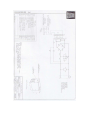
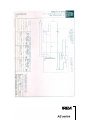
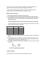
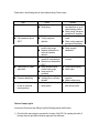
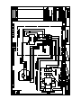
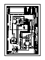
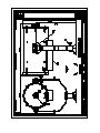
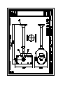
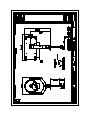
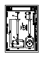
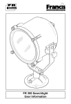
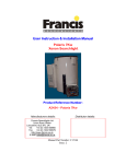
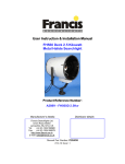
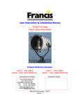
User Instruction & Installation Manual FX380 Manual Control 2Kw Xenon Searchlight Product Reference Number: A2197 – 115v Deck A2781 – 240v Deck A2207 – 115v Deck Pedestal A2724 – 240v Deck Pedestal A2206 – 115v Cabin A2723 – 240v Cabin A2208 – 115v Cabin PedestalA2725 – 240v Cabin Pedestal Manufacturers details: Distributor details: Francis Searchlights Ltd Union Road, Bolton Lancashire, BL2 2HJ, UK Tel: +44 (0) 1204 558960 Fax: +44 (0) 1204 558979 http://www.francis.co.uk E-mail: [email protected] Manual Part Number: C23115 Issue : 5 CONTENTS 1 - Introduction 2 - Safety Precautions 3 - Technical Information 4 - Unpacking and Installation Instructions 5 - Electrical Installation 6 - Operating Instructions 7 - Fault Finding 8 - Maintenance and Servicing 9 - Wiring Diagram & General Assembly Drawings 10 - Spare Parts List 1 - Introduction It is imperative that this manual is read carefully and understood before installing your equipment. For your future reference please keep this manual in a safe place. Thank you for specifying a product from the Francis Searchlights range. All Francis products are designed to give complete customer satisfaction and are manufactured to the highest engineering standards in order to ensure optimum performance and service life. The Francis Xenon range combine features proven over many years service in the most hazardous conditions in both marine and land installations. In order to prolong the life and performance of your product, we recommend that you only specify Francis Searchlights spare parts. This will also ensure that any warranties on your equipment will not be invalidated. Information on spares ordering and parts is provided in this manual. Should you ever need to contact Francis Searchlights Ltd. regarding your equipment, please quote the Product Serial Number at all times. 2 - Safety Precautions The following instructions must be adhered to, in order to ensure a safe working environment and the safety of the user. Note: When unpacking or manoeuvring the searchlight into its fixing position, the lifting handles must be used in order to prevent damage to the equipment or personal injury. Because of the high internal pressure within the lamp, there is a risk of explosion in either a hot or cold state; During operation this lamp emits intense UV radiation which is harmful to the eyes and skin. Suitable protection should be worn; The high luminance of the arc can cause severe damage to the eye if viewed directly. ALWAYS wear suitable protective goggles when viewing the lamp; Always use protective jackets supplied with the lamp; Should it be necessary to examine the lamp with the front bezel removed, always use a protective shield and wear goggles to ensure a safe working environment; Searchlights get hot. Never touch the unit when lit and always allow 15 to 20 minutes for cooling down after turning the searchlight off; Never place anything on or cover the searchlight when in use; Ensure the lamp has cooled sufficiently before removal; If undue force appears necessary to remove the lamp, the equipment should be inspected by a competent person or contact the manufacturer; When disposing of lamps there are several options available: Return the lamp, via the supplier, to the lamp manufacturer in its complete packaging Because of the cold internal pressure of the lamp is approximately 8 bar, the lamp must first be depressurized before disposal. Place the lamp, in its protective jacket, in a plastic bag and drop from a height of 1 to 2 metres onto a hard surface; XBO lamps do not contain materials which are harmful to the environment and thus are not subject to special waste disposal regulations; Due to the vast range of lamps available it may appear possible that more powerful lamps can be used in the equipment than for which it was designed. Even when the unit will physically accept a higher wattage lamp, this substitution is not recommended and is dangerous. This action will also void any warranties on the equipment; Always refer to the lamp manufacturers technical data when dealing with lamps. 3 - Technical Information This product has been designed to operate in accordance with the product specification. The FX380 2000 watt searchlight has the following features: All marine grade materials and fixings; Electronic power supply unit; Parabolic aluminium reflector, electro-formed nickel rhodium plated; Stove enamel painted; Full 360° horizontal rotation; Vertical movement 45° to -25°; Internal self-regulating heater. The searchlight also performs to the following optical data: Xenon light source; Lamp Wattage - 2000 Watts; Supply voltage - 220/240V or 110/115V; Peak Beam Candlepower - 56,031,160 lux; Range - 7,485 metres; Divergence - 1.5°; Temperature range -50°C. In order that the searchlight operates correctly it is imperative that competent personnel are responsible for the installation, operation and servicing of this equipment. Failure to adhere to this advice may cause premature failure or incorrect operation of the searchlight, which may damage the equipment or cause personal injury. Technical information on the Xelamp Power Supply Unit and Ignitor are included overleaf. For more detailed information please contact the manufacturer. PSU ref.: Ignitor ref. Model 8502 (Xelamp) AS-16040A (Irem) Power Supply fixings centres 440 x 152 using M8 screws. Power Supply Details (Model 8502) General Description Output Input Output Adjustments Size Weight Cooling Power Voltage Current Ripple Current Voltage Phase Frequency Width Height Length 1400-2200 watts 22-30 volts D.C. 50-85 amperes D.C. 5% peak-to-peak 25/22 amperes maximum 208/237 VAC Single 60 Hz (50Hz available) 9 steps 12” (30.5 cm) 15” (38 cm) 19” (48.25 cm) 145 lbs. (65.9 Kg) Convection 40 amperes maximum 110/120 VAC Warning When this appears in this text, it indicates a hazard to personnel. Caution When this appears in this text, it indicates a procedure which can result in equipment damage if not properly accomplished. Receiving the Power supply The units are shipped with the power supply bolted to a shipping skid and enclosed in a heavy cardboard cover held in place by banding. Physical damage to the container or its contents should be reported to the carrier immediately. Unpacking Cut the banding strips and lift the cardboard cover off of the unit. Remove the four bolts holding the power supply to the skid. Place the unit in the location selected for installation. Locating the power supply The power supply is convection cooled and the location selected should provide a minimum of 6” clearance around the case. The area should have free movement of air to dissipate the heat generated by operation of the power supply. Provide a space large enough to allow service of the unit if required. Caution Do not allow anything to be placed upon the power supply case; the perforated top is for ventilation and must not be obstructed. Try to select a location as close to the lamphouse as practical. Many users install the power supply adjacent to the searchlight where space is available and local codes permit. Electrical installation and connection Caution Much future grief can be avoided by having a competent electrical contractor install and connect this unit. Caution We make suggestions in this manual as to minimum wire sizes to be used. Refer to, and conform to the codes applicable in your area. Caution Observe polarity of the conductors which carry the D.C. output of the power supply to the lamphouse. Reversed polarity will immediately destroy the xenon bulb upon application of power. Warning When the electrical installation is complete there are two sources of primary power within the unit. Turn off all power when adjusting or servicing the power supply. Warning This unit can run warm to very hot. Allow at least 15 minutes after turning off the power for the unit and its components to cool down before attempting any service procedures. Holes are provided in the end section of the power supply case for conduit entries. Install conduit in a manner which allows some movement for service if required. Refer to drawings for connection information. Model 8502 Primary line: (240v) #10 gauge minimum (110v) #8 gauge minimum; 30 ampere breaker or fuse (240v) 40 ampere breaker or fuse (110v). D.C. output: #4 gauge minimum. Warning The power supplies have two sources of power. Disconnect (turn off) primary power before making adjustments or service procedures. Output power adjustment Warning The power supply stores energy after primary power is switched off. Wait a minimum of two minutes for the capacitor charge to bleed off. Taps are provided on TB1 to alter the output of the power supply. Small current changes may be made by moving the tap from H to M to L. Highest current is on H; the lowest is on L. Larger current changes may be made by moving the tap from 4 to 5 to 6. Highest current is on 4; the lowest is on 6. One input line must be on H, M or L. The second line must be on 4, 5 or 6. When the primary line is high (120/240 VAC), tap 5 or 6 should be used. For 110/208 VAC use any tap, 4, 5 or 6. When changing taps, do not insert wire into the connector so far as to clamp on the insulation rather than the bare wire. Be sure to tighten the connector screws. Routine maintenance Warning The power supply has two sources of power. Turn off power before servicing the unit. Warning This unit can run warm to very hot. Allow at least 15 minutes after turning off the power for the unit and its components to cool down before attempting any service procedures. At 6 month intervals, clean dust out of the unit. Inspect all electrical connections. Look for discoloration due to overheating. Be sure all components are clean and tight. Troubleshooting Much data can be obtained from the volt-ammeter built into the lamphouse control panel. In addition, the following instruments will be needed to perform all trouble-shooting operations that can be done in the field: Portable volt-Ohm-ammeter (VOM) – must be capable of supplying current to forward bias a silicon diode on R X 1 range. (Some digital instruments cannot; consult operator’s manual for instrument concerned.) Clamp-on A.C. ammeter capable of ¼ ampere or better resolution. Xenon lamp power supplies have two stages of operation: 1) 2) Before igniting the bulb – At this time, the voltage at the power supply output terminals reaches “open circuit” value (110 VDC or greater). After igniting the bulb – At this time, the voltage at the power supply output is determined by the load placed on the power supply by the xenon lamp (18-30 VDC). Power supply difficulties can be separated into one of three areas for purposes of diagnosis and repair: A) B) C) Power line problems. Boost circuit (Open circuit voltage) problems. Main power supply problems. A) Primary power problems Power to the power supply is supplied from the sub-panel. The PSU power contactor, K1, will operate when the lamphouse is switched on in the absence of primary power to K1. If there is D.C. voltage out of the power supply as indicted on the lamphouse voltmeter you have primary power. If there is no lamphouse voltmeter, use your VOM. If there is no DC. output voltage and K1 operates, check the primary line with a VOM to locate the point of failure. B) Boost circuit problems (open circuit voltage) Loss of the open circuit voltage due to boost circuit problems will result in the following: Ignitor will not fire in the AUTO mode. Bulb will not light. Disable the lamphouse ignitor by removing primary power to the ignitor. Connect your VOM to the power supply D.C. output. Observe polarity. Turn on the power supply. If you read 110 VDC or more, the boost circuit is operating. If the D.C. voltage is low, on the order of 50 volts, it is likely that diodes 5 and/or 6 have failed. Current limiting resistor R1 may be open. C) Main power supply Power supply bank D1-D4 A shorted diode will cause the primary current to go high and will trip the circuit breaker in the subpanel. An open diode will cause the projected picture to have a pronounced flicker and may result in somewhat lower operating current. Capacitors C1-C2-C3 A shorted capacitor or capacitors will raise the primary current and trip the circuit breaker in the sub-panel. C1-C2-C3 If these are open or have lost capacity (ability to store energy) they will cause either a noticeable flicker in the projected picture or ignition problems or both. If in doubt, disconnect the capacitors one at a time. After disconnecting a capacitor, if no change in ignition or flicker is observed, then the capacitor is having no effect. Replace it. Low capacity or an open capacitor affect ignition because there is insufficient surge current to reliably light the bulb. If disconnecting a capacitor does change either flicker or ignition, then the capacitor is functioning. Reconnect it. High ripple current caused by a diode failure will result in overheating of R3. You may use a clamp-on A.C. ammeter on the common D.C. line to the capacitor bank as an indirect method of checking ripple. The 8502 capacitor bank will have a nominal 25 ampere (AC) current flow. Higher current indicates a high ripple condition. Lower currents, may indicate open or deteriorated capacitors. Current into the capacitor bank varies with adjustment of the power output. As the output power is decreased, current flow of the capacitor bank will decrease. Diode testing and replacement To test a diode it must be disconnected from the circuit in which it is used. In many failure modes, the diode failure can be tentatively identified by discoloration of the bright surface because of excessive heat. You will still have to disconnect the diode and make further checks to verify failure. After disconnecting the diode, sue your VOM on the R x 1 scale. With the meter leads connected in one direction, the reading should be zero or close to it; reversing the meter leads, the indication should be a very high resistance. If the diodes does not exhibit these characteristics, replace it. If you have removed a diode from its heatsink or you are installing a new diode, observe the following instructions: Clean the area of the heaksink in which the diode is to be installed. Warning You must use heatsink compound. It is caustic in nature. Do not use for fingers; keep it away from your eyes; and do not ingest. Follow instructions on the container in which the compound is packaged. You may obtain heatsink compound at your local electronics dealer. Apply the compound with a wood or plastic spatula; a popsicle stick will work well. A thin layer of compound is adequate. Use internal star washers as opposed to split washers. When tightening the diodes in the model 8502 power supply, the torque should be 90 in.lbs., 125 in.lbs. In replacing diodes, observe polarity. Model 8502 – diodes 1-3 are 1N3291R types, diodes 2-4 are 1N3291S types. 4 - Unpacking and Installation Instructions The following instructions should be read and fully understood prior to installing the equipment to ensure that the correct procedures are followed and all safety precautions are observed. Note: If the equipment has been in storage for a considerable amount of time, it is advisable to conduct a routine maintenance check on all parts before installation. Safety Precautions This equipment should not be connected to an electrical supply before being installed. Installation procedures should be adhered to in order to ensure a safe working environment and reduce the risk of damage or personal injury. Preparing the Mounting Position Mark out and drill the fixing holes through the deck. Fit the ‘O’ ring in position and bolt the searchlight base securely. On an uneven surface it is necessary to use a suitable sealant, such as silicone, in order to ensure a weatherproofed joint. If anti-vibration mounts are to be fitted, the fixing holes for the mounts should also be marked out and drilled. Prior to manoeuvring the searchlight into its’ fixing position, the AV mounts should be fitted to the base. When in the desired position, bolt the searchlight firmly down. 5 - Electrical Installation For safety purposes, only competent personnel should perform the electrical installation. All equipment should be installed to current Electrical Regulations and Standards. In order to obtain the maximum light output from the searchlight, it is essential that the full operating voltage of the lamp fitted be applied to the lampholder contacts. Method of Electrical Connection 1) Disconnect the supply before working on the electrical system; 2) The searchlight must be connected to a fused electrical supply, using suitably sized cable; 3) If the searchlight is located a considerable distance from the supply, provision must be made in the cable size in order to overcome the voltage drop. The following table should be used for indication purposes only: The PSU should NOT be positioned no more then 5 meters away from the searchlight. The following table below indicates the maximum length of cable to be used for the AC supply cable, from the control panel to the searchlight: Searchlight 115v 2Kw 240v 2Kw Cable Size (mm²) Distance Max Distance Max 1.5 8 MTRS 37 MTRS 2.5 14 MTRS 60 MTRS 4 22 MTRS 96 MTRS 6 34 MTRS 150 MTRS 10 57 MTRS 250 MTRS 4) Whenever possible cable terminations should be made below deck and with approved terminal devices; 5) If a spare auxiliary fuse or circuit breaker is not available, one of the correct type and rating should be fitted and connected to a positive supply. It is advisable to locate a bus bar or main connection and avoid any direct connection to the supply; 6) For 110/220v AC products, the following colour coding system should be used for the customer supply cable: Brown Blue Green/Yellow - Live - Negative - Earth Note: This equipment must be earthed. Installation Guidelines A typical installation and connection routine for the searchlights is as follows: Referring to wiring diagram C23114, a supply is fed to the PSU, which then provides a common feed to all other functions and equipment. Cables required to be connected by the customer: 4 core 6mm cable from the S/L into the PSU, doubling up the pairs, 3 core 1.5mm cable from the S/L into the PSU, 3 core 1.5mm cable to the Heater in the Searchlight, (customer may need to provide a suitable junction box to extend these three cables – 3 metres supplied) & the mains cable to the PSU (to be supplied by the customer). The searchlight head is pre-wired. When the light is in operation the output from the PSU should be approximately 24v dc at 80amps. Basic Operation When the searchlight is switched on a 240v or 115v supply is fed to the PSU and linked to the ignitor. Also from the PSU, a dc output is fed to the lamp. The ignitor ionises the gas within the lamp and this strikes the light. Fitting instructions for the 2Kw xenon lamp Referring to the diagram overleaf: 1) Unfasten the eight Latches (A) on the front and rear of the searchlight; 2) Remove the front bezel (B) and rear bezel (C) assemblies; 3) Unscrew the two M6 hexagon screws (D) from the front lampholder mounting block (E) and remove the front lampholder assembly from the mounting bracket; 4) Loosen the knurled screw on the front (F)and rear (G) lampholder assembles; 5) From the rear, unscrew the P.T.F.E. bush (H) and remove the countersunk screw (J). Now you can remove the rear lampholder socket (K) and fix the negative end of the lamp using the M8 x 10 grubscrew (L) 6) The lamp can now be inserted, make sure that the negative (cathode) end of the lamp is towards the rear of the searchlight, re-fit item (H) & )J); 7) Tighten the knurled screw (G) on the rear lampholder assembly to hold the lamp in position; 8) Fasten the front lampholder mounting block back in position, it will be necessary to pull the front socket against its spring to fit over the lamp. When in place tighten the front knurled screw (F); 9) Fasten the front and rear lampholder leads as wiring diagram, ensuring the connections are secure; 10) The front bezel and rear bezel can now be replaced; 11) Removal is the reverse of the above; 6 – Operating Instructions This equipment is designed for use out of doors, in free air. Never place anything on, or cover the searchlight when in use as this may present a hazard. The PSU should be housed below deck/in doors. Never leave the PSU exposed to weather conditions. The searchlight can be positioned using the elevation and baseplate lockwheels. When in the desired position the lockwheels must be securely fastened to prevent damage. The beam of the searchlight can be adjusted to give a variety of beam types. By turning the focus lockwheel positioned on the Rear bezel assembly clockwise/anti-clockwise, the lamp holder mechanism moves through spot to flood positions. When the desired beam is achieved simply release the lockwheel. Please note that it is advisable to leave the heater permanently on in order to remove condensation from the searchlight head. The heater specified on this equipment is self-regulating and will shut off when it reaches the dew point temperature. This product should not be used for any purpose other than for which it was designed. Any modifications to the product should not be undertaken without consulting the manufacturer. Setting to Work Safe service in use necessitates the strict observance of the following precautions. Any article fabricated from quartz or glass is inherently fragile and care should therefore be taken, at all times, when handling lamps; Eye protection must be worn when handling lamps that have been removed from their packaging materials. The protective jacket should not be removed from the lamp for safety reasons, as there is a remote possibility of the lamp shattering violently, especially if it is subjected to mechanical shock or vibration; Ensure that the power rating of the Xenon lamp to be fitted is suitable for the lamphouse and power supply equipment (rectifier); Always isolate the equipment from the supply before inserting a lamp; Before inserting the lamp ensure that all contacts are clean. Contacts must be renewed at the slightest sign of corrosion. Sanding or filing down corroded areas is not recommended as this will only make the conducting surface between the pin and lampholder smaller, thus causing the lamp to overheat; The inert gas (Xenon) used in XBO lamps are under a pressure of several bar even when the bulb is cold. FOR SAFETY REASONS THE LAMP MAY ONLY BE INSERTED INTO THE LAMPHOUSE WITH THE PROTECTIVE JACKET FITTED; Do not twist or bend the fused quartz bulb when fitting the lamp as mechanical stresses MUST be avoided; Ensure that the spring contacts firmly surround the pins on the cap of the lamp. Do not apply unnecessary force when tightening the screws; After inserting the lamp, ensure that there is sufficient axial play in the lampholder. The lamp must be capable of unimpeded expansion when it warms up to operating temperature. Mechanical forces must not be applied to the fused quartz bulb; Electrical leads must be arranged in such a way that there is a sufficient air gap (approximately 40mm) between them and the lamphouse, in order to prevent flashovers from the ignition voltage. All flexible leads must have strain-relieving clamps; Before putting the lamp into service for the first time, check the polarity of the electrical connections. INCORRECT POLARITY WILL CAUSE IMMEDIATE DESTRUCTION OF THE LAMP; Before the protective jacket is removed, suitable protection must be worn i.e. face mask and gloves with wrist protection; Never touch the quartz bulb with bare hands, as fingerprints will make the glass cloudy and cause a severe loss of light. This may also cause recrystallisation and thus weaken the bulb material. Should the bulb be inadvertently touched, remove fingerprints with methylated spirit and a clean, soft paper towel. The bulb should then be wiped with distilled water. (NOTE: ALWAYS WEAR MASK AND GLOVES DURING CLEANING); All packaging and the protective jacket must be retained for re-use. Whenever removing a lamp, the protective jacket must always be used for safety reasons; Notes: 1) XBO lamps are designed for dc operation only. The dc current may only be varied within the limits of the current control range. An XBO lamp operates best at rated current; over the life of 2) 3) 4) 5) the lamp, the current may be increased to its maximum value to compensate for loss of light. The output of the lamp can be reduced by operating the lamp at minimum current but this does not prolong the life of the lamp; For safety reasons, XBO lamps should be replaced once they reach the end of their average lamp life, and not later than 1.25 times they’re average lamp life. After this time there is an increased risk of the lamp exploding; The anode (positive cap marked ‘+’) must be on top when the lamp is inserted in the vertical position. If the anode is incorrectly inserted the arc will be unstable, the bulb will blacken more quickly and the lamp will prematurely fail; The HT lead from the high voltage terminal of the ignitor, must be connected to the cathode (negative cap marked ‘-‘). If the lamp is connected with the wrong polarity it will be irreparably damaged after a very short time. In all circumstance the lamp manufacturers data should be referred to when dealing with lamps. 7- Fault Finding All fault finding must be conducted by a competent person or qualified Electrical Engineer. Please refer to the following table for the trouble-shooting of Xenon lamps. Fault Wrong Polarity Cause Lamp incorrectly fitted Faulty wiring Cap overheated Cap temperature above 230°C Faulty contacts Cooling equipment defective Arc unsteady Lamp operated outside current control range Magnetic stabilisation for horizontal operation defective Crack in graded seal caused by overheated cap Maximum cap temperature 230°C Lamp operated outside current control range Lamp service life exceeded Current ripple too high Auxiliary mirror incorrectly adjusted Lamp operated too long in same position Bulb draws in air Glass erosion on fused quartz bulb Electrodes damaged Premature blackening Asymmetrical blackening of lamp (in horizontal burning position) Remedy Anode (large electrode) must always be on top in vertical burning position Check polarity, transpose connections if necessary Check terminals, tighten or renew Check cooling equipment and replace if necessary Correct current setting Check magnetic stabilisation Check terminals - tighten or renew Correct current setting Check meter Have power supply inspected Adjust auxiliary mirror Turn lamp through 180° after half service life Failure of Lamp to Ignite In the event of the xenon lamp failing to light the following steps should be taken: 1) Check that the mains supply is connected to the input of the PSU. On operating the switch, if the lamp does not light switch off mains supply and check all fuses; 2) On pressing remote starting switch the lamp still does not ignite, check the searchlight head. On your command get an operator to activate the starting switch for approximately 10 seconds. During this time listen for any noise (cracking or hissing) coming from within the barrel. If this arcing is heard switch off the supply at the mains. Remove the rear bezel to expose the two supply leads to the xenon lamp. Using a dry cloth wipe these leads to remove any dust, moisture or condensation that may have formed around the inside of the barrel. Replace the rear bezel, ensuring the latches are located, and perform the check again, listening for the cracking. If the lamp still fails to ignite, switch off at the mains and replace the xenon lamp in accordance with the safety procedures within this manual and the manufacturers’ information. Any further tests to be carried out with regards to lamp failure must be conducted by a competent electrical engineer and should not be carried out in an explosive atmosphere. 3) Before a xenon lamp will ignite, the electrically insulated gas between the electrodes must be ionised. This is done by the ignitor which produces a high frequency voltage (up to 30,000 volts or higher). The ignitor is activated by switching the lamp on and a crackling or hissing noise should be heard. The ignitor is housed within the rear of the searchlight barrel. This is a totally encapsulated unit and repair is not advised. If found to be faulty a new ignitor must be fitted. 8 - Maintenance and Servicing In order to prolong the service life and performance of your searchlight, the following maintenance guidelines are recommended: Maintenance checks should be conducted before every voyage or at least every three months; Before checking, disconnect the equipment from the supply; Visually inspect the condition of the equipment; Any major or minor structural damage should be rectified immediately in order to reduce sympathetic wear; After inspection it may be necessary to clean the inside of the searchlight. The following procedure should be adhered to: Remove the front bezel; Clean the front glass inside and out using a proprietary glass cleaner or metal polish; Clean the reflector if required; Check the reflector mounting gaskets. If signs of corrosion or damage are evident, replace as necessary; Ensure that the lampholder is free from corrosion or other damage; Check earthing point for conductivity; It is advisable to check all seals and gaskets for signs of degradation. Renew if necessary; Upon completing all maintenance requirements the searchlight should be tested for full working order (approximately 20 minutes). Every six months the external movement mechanisms i.e. lockwheels, elevation and pan mechanisms, should be lightly lubricated. If in any doubt as to the correct servicing procedures to adopt please contact your distributor/agent or the manufacturer who will be able to advise the best course of action for your product. 9 - Wiring Diagram & General Assembly Drawings Drawing Number Description C23114 240v Xenon Wiring Diagram C24495 115v Xenon Wiring Diagram A2781 FX380 Deck General Assembly A2724 FX380 Deck Pedestal General Assembly A2723 FX380 Cabin General Assembly A2725 FX380 Cabin Pedestal General Assembly 10 - Spare Parts List The following spare parts can be ordered directly from the manufacturer: Part Number Description C15392-00 C23860-00 C12081-00 C12080-00 C20224-00 C21573-00 D20195 C08919-00 C08920-00 C23277-01 C13737-00 C21502-01 C21503-01 C11148-00 C10170-00 C20281-00 C22072-00 Power supply unit (240v) Step Up Transformer Ignitor (240V) Ignitor (115v) Fan (240V) Fan (115v) Lamp Front glass Front glass gasket Heater & Fuse Assembly Reflector Base lockwheel assembly Side lockwheel assembly ‘O’ ring seal (Deck & Cabin) ‘O’ ring seal (Deck Ped & Cabin Ped) Bellows Seal In order to prolong the life and performance of your product, we recommend that you only specify Francis Searchlights spare parts. This will ensure that any warranties on your equipment will not be invalidated. When ordering spare parts please contact the Sales Department at Francis Searchlights Limited. Please quote searchlight model and serial number at all times. This will enable a fast response to your spares requirements