1
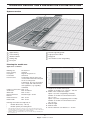
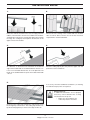
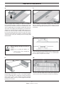
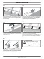
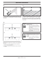
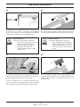
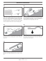
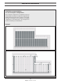
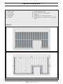
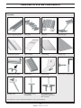
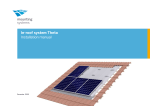
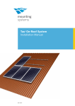
In-roof system Kappa
Installation manual
Artikelnummer: 810-0022
Introduction & Safety
Short description
About this manual
Kappa has been specifically designed for direct integration
of unframed photovoltaic modules into the roof cladding,
irrespective of the roof covering. All components are adapted to the specific order and will replace the current regular
roof covering.
Kappa is fixed onto the existing or, if need be, onto additional new roof battens. In this way, either part of the roof or its
entirety can be covered in PV modules.
Subject
This manual details the installation of the roof-integration
system Kappa.
Intended use
Basic safety instructions
The roof-integration system Kappa is to be used for the roof
mounting of photovoltaic modules only. Mounting Systems
is not liable for damages resulting from failling to comply
with the installation instructions, particularly the safety
instructions, as well as misuse of the product.
The following basic safety instructions and the warning notes
are an essential part of this manual and are of fundamental
importance for handling the product:
User group
The manual is intended for qualified personnel with a basic
knowledge of mechanics, hand tools and mechanical skills.
Standards and technical directives
|
Regardless of the structural analyses, it must be ensured
for every installation that the product meets the static requirements on site according to the local jurisdiction having authority for such installation.
When planned correctly, Kappa fulfills the following standards
and technical directives:
|
Comply with the relevant safety regulations.
|
Eurocode 1: Actions on structures - Part 1-3:
General actions; snow loads; EN 1991-1-3:2003
|
The presence of a second party who can provide help in the event of an accident is obligatory during the entire
installation process.
|
Eurocode 1: Actions on structure - Part 1-4:
General actions; wind loads; EN 1991-1-4:2005
|
Keep a copy of this installation manual in the immediate vicinity of the system.
|
Eurocode 9 - DIN V ENV 1999
|
DIN 1055 Actions on structures - Part 100: Basis of design, safety concept and design rules
|
DIN 1055 Actions on structures, Part 4: Wind loads
|
DIN 1055 Actions on structures, Part 5: Snow and ice loads
2
Kappa Installation manual
SAfety
Working on roofs
Responsibilities of the operator
When working on roofs, note the following instructions:
Modifications to Mounting Systems equipment may be performed only by authorized personnel.
The operator of the system has the following safety related
responsibilities:
|
Pay attention to accident prevention regulations for
working on roofs. If appropriate, use a barrier to protect against falling parts.
|
In line with accident prevention regulations, work on roofs should be carried out using safety harnesses for individuals or safety scaffolding.
|
Observe the relevant local safety regulations.
|
Before stepping on to the roof, check the load-bearing capability of all parts which are under stress.
|
Use fall protection.
|
Use protective equipment to guard against falling even when carrying out short jobs.
|
Do not carry materials on to the roof via ladders, but rather use suitable lifting gear.
|
Performing recommended maintenance work.
| Ensuring that the installation of the frame is performed only by qualified personnel with adequate skill and know-
ledge.
|
|
Ensuring that the assigned installation personnel can
evaluate the work assigned and recognize possible
dangers.
|
Ensuring that the installation manual and particularly
the safety instructions are read and understood by
the authorized installation personnel prior to beginning
the work.
Warnings
|
Ensuring that the work site safety regulations and requirements are observed.
The warning notes used in this manual identify safety
related information. They consist of:
|
Ensuring that suitable lifting devices are used for the ins- tallation.
|
Warning symbol (pictograph)
|
Indicator word to denote the danger level
|
Information about type and source of the danger
|
Information about possible consequences if the
instructions is not observed
|
Measures for avoiding the danger and for preventing injuries or property damages
Ensuring that the installation manual is available during the installation. The installation manual is part of the
product.
The heading of the warning notes identifies one of the following danger levels:
Caution
Denotes a potential risk which may lead to
physical injury and property damage.
3
Kappa Installation manual
Technical description & Preparation for installation
System overview
a
g
h
i
f
d
e
b
c
a
b
c
d
e
f
Upper flashing
Lateral flashing
Additional batten
Sealing strip
Eaves part
Module supporting profile
Edge protection rubber
Ridge part
Inter-module suction safeguarding
g
h
i
Planning the modul area
Application conditions
Building site:
Roof covering:
Roof pitch:
PV-module:
Roof structure:
Height of construction:
Snow load:
Wind load:
Distance between battens:
Batten thickness:
Batten width:
2.
Pitched roof
Optional
Regular roof pitch 23°*
Unframed
The bearing capacity of the roof
construction needs to be adequate
for the occuring loads.
Furthermore, the roof construction
must comply with national norms
and regulations (e.g. regarding
ventilation)
Max. 12 m
Max. 0.7 kN/m²**
Max. 32 m/s**
Module height - 20 mm
Min. 35 mm
Min. 35 mm
Planning the module area depends on:
|
Module dimension (L x W x H)
|
Module quantity and arrangement
*
**
When deviating from this pitch or when the roof is exposed to higher-than-average strain, adequate counter-measures might need to be taken in accordance with national
norms and regulations (e.g. installation of a sarking membran).
Maximum values can vary depending on the size of module, the type of building and
the construction site.
4.
5.
1.
3.
5.
1.
2.
3.
4.
5.
Height of the module field equals:
Number of modules x (3. - 20 mm) + 150 mm
Width of the module field equals:
Option 1 (Suction safeguarding standard):
Number of modules in horizontal direction x
(4. + 13 mm)
Option 2 (Suction safeguarding with T-Profile):
Number of modules in horizontal direction x
(4. + 16 mm)
Module height
Module width
Distance between roof battens: 3. - 20 mm
4
Kappa Installation manual
Technical description & Preparation for installation
Additional battens
Preparation for installation
If the existing battens are not in the correct places
required for the installation of Kappa, additional battens
are necessary for:
|
the fixation of the module support profiles
|
the fixation of the sealing strip
|
the fixation of the upper flashing.
Neither battens nor the small parts to fix them to the roof
are included in the delivery.
Mounting Systems recommends that you inform yourself
about the
on-site conditions, especially about
| the type and condition of the roof,
| the dimensions of the battens,
| the quality of the battens and
| the distance between battens.
Notes on planning
When planning your module field, please note the following:
|
The standard components of Kappa have
been designed for the integration of modules
into tile roofs. The flashing for the connection to other roof types might have to be adapted by a
roofer.
|
Between the ridge and the module field, at least
three rows of tiles should remain in place. Otherwise, this connection must be executed by a profes-
sional roofer to ensure correct functioning.
|
Direct connections to either eaves, ridge or gable must to be executed by a professional roofer.
Overview of required tools
|
|
|
|
|
|
|
|
|
|
|
|
10 mm spanner
Cordless screwdriver and bits
Pair of metal shears
Scissors or a knife
Sheet metal pipe reducer pliers (for flashing) or other adequate tool for treatment of aluminum flashing
Angle grinder with stone disk
Hammer (plus nails for securing the battens)
Saw
Battens
String
Stanley knife or similar
Spacer gauge
5
Kappa Installation manual
Installation Kappa
1.
2.
Before the modules are taken to the roof, the edge protection
rubbers, which must be cut to the exact width of the modules,
should be pressed onto the module edge that points towards
the ridge. The sealing lip should point in the direction of the
upper surface of the module.
Remove the roof covering in the module field area. On both
sides as well as above, remove one row of tiles more than
required for the actual module field.
3.
4.
At a distance “a“ above the last roof batten at the bottom
edge of the module field, fix an additional batten. Distance “a“
is 10-12 cm for Double Roman tiles, 10 cm for plain tiles. The
length of the additional batten equals the module field width
+ 40 cm.
Bend the sealing strip by 90° away from the upper side and
position it over the new batten.
5.
If necessary, fix further additional roof battens (cf. Planning
the module area p.4) in the correct places.
Material damage
If additional roof battens are not properly
fixed, they cannot withstand the occuring
wind loads and can rip out.
| Make sure all new battens are
sufficiently fixed to the rafters.
Ensure that the sealing strip overlaps the adjacent tiles to the
left and right by at least 20 cm. The sealing strip should overlap the underlying tiles by as much as the adjacent tiles do.
6
Kappa Installation manual
installation Kappa
6.
7.
Prepare enough lateral flashings to allow an overlap of
20 cm between flashings. Position the flashing sheets with
the wider side towards the outside of the module field (cf. Size
of the module field p.4). The modules should reach the inner
side of the raised ridge of the flashing sheet. The lowest flashing sheets should overlap the sealing strip by at least 8 cm.
Position the short eaves part centrally on the aditional batten and in the lateral direction on the inner side of the sheet.
Secure the sheet and the eaves part by screwing two roofing
screws through eaves part, flashing sheet and sealing strip
into the batten.
When installing several lateral flashings, have them overlap each other by at least 20 cm. Treat the edges of the flashings with the appropriate plumbing tools so that they fit into
oneanother.
Material damage through incorrectly set
screws
Screws not set centrally into battens can
rip out.
| Drill all roofing screws centrally into the roof battens.
8.
Fit the remaining eaves parts likewise with 2 roofing screws
each, as shown in figures 6, 10 und 11. It is essential that
the eaves parts are spaced accurately.
9.
10.
Set the spacer gauge so that, for the modules along the right
and left edges, the module + 5 mm (+ 7 mm when using the
suction safeguarding with T-Profile) fits exactly between the
angle sections. For the center modules, the gauge should be
set to module width + 10 mm (+ 13 mm using the suction safeguarding with T-Profile).
Place the 3 mm thick angle sections of the spacer gauge in the
centre channels of the eaves parts to find the exact spacing.
7
Kappa Installation manual
Installation Kappa
11.
12.
Watch out at the edges of the module field! Here, measure the
outer edge to the centre channel, not the distance between
the centre channels.
Now that the sealing strip is secured by eaves parts, bend up
the edge of the sealing strip again to create a 90° angle pointing upwards (protection against flying snow).
13.
14.
The next step is to slot the outer supporting profiles into the
eaves parts and then to position them so that eaves part and
support profile are flush.
Run a length of string between the outer profiles. Slot the next
profiles into place and align them to the string.
If you are using the standard suction safeguarding, press two
plastic sleeves firmly into the mid-channel of each middle profile.
15.
Material damage
Badly inter-looked profiles can rip out.
| When installing module supporting profiles and ridge pieces, the super-
posing profiles must be correctly inter-locked. A loud click should be heard.
Fit the modules to the roof and wire them up. Push two hook
inserts onto the lower edge of each module at the appropriate
places and push the modules, together with the hook inserts,
into the module hooks on the supporting profiles.
8
Kappa Installation manual
Installation Kappa
16.
17.
Cut off the rubber section protruding the module hooks using
a sharp knife, e.g. a Stanley knife. Be careful not to damage
the module.
Now align the supporting profiles precisely to the modules
(the plastic sleeves or loosely placed T-suction safeguardings help with ensuring there is the necessary gap between
the modules) and secure the aligned profiles with 2 roofing
screws each.
18.
a)
Material damage
Unduely stressed modules can break.
| Take care not to push the laminates too firmly against the plastic sleeves or T-Profiles.
| When fastening the suction safe-
guardings, do not make the washer or T-Profile bend down the module (torque 2 Nm).
b)
Material damage through incorrectly set
screws
Screws not set centrally into battens can
rip out.
| Drill all roofing screws centrally into the roof battens.
Secure modules using the inter-module suction safeguarding
elements:
a) screw one screw with sealing washer into each plastic sleeve (2 sleeves per profile) or
b) screw two T-Profiles into each profile, using 2 screws per T-Profile.
9
Kappa Installation manual
Installation Kappa
19.
20.
Fit the edge suction safeguarding element: secure the outer
modules of each row with 2 L-brackets and self-tapping
screws each. To do this, secure the L-brackets to the support
section from the outside with the self-tapping screws.
Secure the modules at the top edge by slotting in the next row
of module supporting profiles and pushing them downwards
as far as they will go. Note that the cells must not be covered.
Material damage
Unduely stressed modules can break.
| Take care not to push the L-bracket too firmly against the laminate
| When fastening the suction safe
guardings, do not make the
L-bracket bend down the module
(torque 2 Nm).
Material damage
Badly inter-locked profiles can rip out.
| When installing module supporting
profiles and ridge pieces, the super posing profiles must be correctly inter-locked. A loud click should be heard.
21.
22.
For optimum sealing, cut into the lip of the edge protection
rubber to the left and right of the module hooks so that the
lip stands upright again directly next to the hooks .
Secure the topmost module row using the ridge parts. To
do this, slot the ridge parts into the supporting profiles and
push them down as far as they will go. The hooks must not
cover the cells.
Secure the additional rows according to installation steps
15 - 21. The method of closing the topmost row of modules
at the ridge is described in the following installation steps.
10
Kappa Installation manual
Installation Kappa
23.
24.
Prepare the two upper flashing sheets at the right and left
edges of the module field in the way shown in the drawing.
First of all, cut out the superfluous material using tin snips
then make the additional cut “x“. Now bend the middle section downwards by 90°, and then the section on the module
side. Do not bend or remove the section on the ridge side.
Now fit the flashing sheet with its short side into the hooks
of the ridge parts. If more than one sheet is required, these
must be sealed professionally. If necessary, position an
additional batten at the upper edge of the sheet.
25.
26.
The flashing sheet is secured indirectly at the ridge using
retaining clips. Fix the retaining clips to a batten using roofing screws.
Fit the remaining missing tiles. Fit the tile covering up to the
raised ridge of the flashing sheet. If necessary, cut the tiles.
Clamp or nail the tiles into place.
27.
Fit the tile covering up to approximately the centre of the sloping part of the upper flashing sheet. If necessary, cut the
tiles.
11
Kappa Installation manual
Installation Kappa
Installation recommendations
for non-rectangular configurations
Non-rectangular configurations are implemented using an
inner flashing sheet (without a middle raised ridge along its
length) and shortened rails (only in variant 2). The installation steps are analogous to the installation of rectangular
configurations as described above. The arrangement of
the rails and flashing is described below.
Variant 1
i
a
h
i
b
i
a
i
h
f
c
c
e
i
d
12
Kappa Installation manual
Installation Kappa
a
Upper flashing
f
Module supporting profile
b
Inner flashing
g
Shortened module supporting profile
c
Lateral flashing
h
Ridge part
d
Sealing strip
i
Roof battens in accordance with manual
e
Eaves part
j
Additional batten for shortened module supporting
profile
Variant 2
i
a
j
h
e
i
d
j
g
g
b
f
c
e
b
c
e
d
13
Kappa Installation manual
d
Overview of system components
Overview
Module supporting profile
Eaves part
Ridge part
Spacer gauge
Lateral flashing sheet
Upper flashing
Inner flashing
Sealing strip
Edge protection rubber
Hook inserts
Retaining clip
Edge suction safeguarding
Roofing screw
Inter-module suction
safeguarding
Inter-module suction
safeguarding (alternative
with T-Profile)
The quantity of system components depends on the system ordered.
14
Kappa Installation manual
Mounting Systems GmbH
Mittenwalder Straße 9a
D 15834 Rangsdorf
Tel. +49 (0) 33708 529-0
Fax +49 (0) 33708 529-199
[email protected]
www.mounting-systems.de
Subject to technical alterations
2010 © Mounting Systems GmbH