1
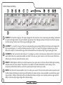
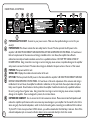
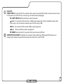
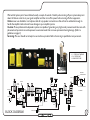
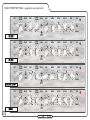
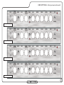
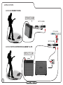
L5T-112
2
The Dark Art: In an age where guitar players have developed an unhealthy
fascination with pre-amp distortion, the fabled sound of a tube power amp being
pushed hard has almost passed into history. Until now that is!
The L5T-112’s 5W Class A Single Ended output stage oozes classic, warm tube tones: The harder you drive it, the better it sounds.
Plus with enough gain for contemporary tones, it also has a mean, spiteful side to it as well – making it ideal for any style of playing.
Perfect for studio and practice use, but also equally at home or on stage plugged into a Laney LT-212 cabinet, the sound will blow
you away.
Every Lionheart product is extensively play tested by experienced guitarists
before being shipped to our customers. Only when the unit is finished to our
complete satisfaction is it assigned its own unique build number which is then
hand stamped onto the rear mounted plaque.
Your L5T-112 should give you years of trouble-free amplification, however
please take time to read this manual and familiarise yourself with the controls
as it will allow you to get the best from your amplifier. We hope you enjoy
using your L5T-112 as much as we enjoyed designing and making it.
Best wishes from all at Laney
3
FRONT PANEL CONTROLS
CLEAN
VOLUME
INPUT
LO
4
5
3
4
7
8
1
9
0
10
DRIVE
VOLUME
DRIVE
6
2
HI
BRIGHT
5
4
6
3
7
2
5
3
9
0
10
8
1
9
0
BASS
4
7
8 2
1
DRIVE
6
10
5
MIDDLE
4
6
3
7
2
5
3
7
8 2
1
9
0
10
TREBLE
4
6
5
3
9
0
10
4
7
8 2
1
REVERB
6
5
3
7
8 2
1
9
0
10
RUN
TONE
4
6
5
6
3
7
8 2
1
9
0
10
8
1
9
0
10
STANDBY
HI INPUT: ‘Hi’ stands for high gain. This input is designed for the connection of low output level guitars making it well suited
for guitars with single coiled or low gain humbucker type pickups. Use of high gain pickups in this input may drive the preamp
too hard causing a "mushy" sound. Only use good quality guitar cable.
LO INPUT: ‘Lo’ stands for low gain. This input is attenuated down approximately 50% from the Hi input and is designed for
high output level guitars. It is useful in obtaining output that is "tight" not "mushy" from high gain humbucker type pickups.
Also use this input for the cleanest full range sound with extended low end response. Only use good quality guitar cable.
CLEAN VOL: Sets how loud the clean channel is. Try cranking it up a little to drive the power tubes harder for that real retro
sound and feel that only a quality tube amplifier can deliver. Now use your guitar volume to control the amount of distortion.
(Wind it up for distortion back it off a little for clean)
BRIGHT: Adds brightness and life to the treble frequencies of your guitar when on the clean channel. Adds edge and picking
emphasis when on the drive channel. The switch has more effect at low Clean Volume/Drive control settings. Use in
conjunction with the Treble and Tone controls for optimum performance. Switch up to enable.
DRIVE: Sets the level of tube preamplifier drive or how dirty your sound is. This control should be used in conjunction with
the Drive Volume (6) Setting low levels of gain with high levels of volume will give a clean preamplifier sound with tube output
stage overdrive. Setting a medium drive level and medium Drive Volume will give a nice crisp bluesy lead tone, again with the
ability to drive the output stage at higher Drive Volume settings.
4
Setting a high level on the Drive control and a low setting on the Drive Volume will give you a punchy hard rock lead
tone, with the ability to again drive the output tubes at higher Drive volume settings. Having set the Drive and Drive
Volume controls to your desired sound try backing off your guitar volume and tone controls for lots of other cool
sounds. Good tube amplifiers have the unique ability to produce a wide range of sounds by using only your guitar
controls, playing weight and style.
DRIVE VOL: Sets how loud the 'Drive' channel is. It is useful to experiment with drive levels and drive volumes. If you
want a very open, warm and semi overdriven sound try reducing the amount of drive and increasing the drive volume.
This reduces pre-amp gain but pushes the power amp section and makes it work harder giving you a very desirable level
of power amp distortion which is a very pleasing “retro” style sound.
DRIVE SWITCH: Switch up to enable the 'Drive' channel. (This switch must be in the down (OFF) position in order
for the drive to be switched remotely via a foot switch.)
DRIVE LED: This led will illuminate when the Drive channel is activated with the Drive switch (8) or the included
Laney FS2 remote footswitch.
BASS, MIDDLE,TREBLE: These are a traditional set of passive tone controls. Passive controls have the advantage of
always sounding musical at any of their settings mainly due to their unique interactive nature. This gives players a more
natural set of tools to create their ideal sound. (Try them all set at midway (5) as a good starting point)
REVERB: Controls how loud the built in reverb sounds.
TONE: The tone control works in a similar fashion to the Tone control you probably have on your guitar except that it
uniquely works at the other end of the amplification chain. This has the ability to not only control the overall top end
response but also reduce upper end harmonics on the output stage and preamplifier overdrive sounds. This will give you
bright cutting sounds at high settings and smooth rounded sounds at lower settings. (Midway (5) is a good starting point)
STANDBY SWITCH: Disconnects the main HT voltage from the tubes but keeps the tubes warm so that they are
ready to go instantly. Switch to standby for short breaks when you don’t want to wait for the tubes to warm up again.
POWER LED: This led will be lit when the amplifier is switched on.
(Always switch off and disconnect the power cord when not in use)
5
REAR PANEL CONTROLS
8
L Z B1 2 3 4
6
POWER INLET SOCKET: Connect to your power source. Make sure the specified voltage is correct for your
country!
POWER FUSE: This drawer contains the main safety fuse for the unit. The fuse protects the AC power to the
amplifier. USE ONLY THE CORRECT SIZE AND RATING OF FUSE AS SPECIFIED ON THE PANEL. If a fuse blows or
fails and a replacement of the same size and rating is installed and it in turn blows, the amplifier has suffered a
malfunction internally and needs immediate service from a qualified technician. DO NOT TRY USING A FUSE OF
HIGHER RATING. Using a fuse that is too large in current rating may cause serious, irreparable damage to the amplifier
and presents a serious fire hazard. The mains fuse ratings are detailed in the specs section at the rear of this manual
POWER: Main power switch for unit.
SERIAL NO: Displays the model and serial number of the unit.
HT FUSE: This fuse protects the DC power to the tubes within the amplifier. USE ONLY THE CORRECT SIZE AND
RATING FUSE AS SPECIFIED ON THE PANEL. If a fuse blows or fails and a replacement of the same size and rating is
installed and it in turn blows, the amplifier has suffered a malfunction, at this point check the output tubes and replace
faulty ones if required. Should tubes not be the problem the amplifier should be checked out by a qualified technician.
Do not try using a fuse of greater value. Using a fuse that is too large in current rating may cause serious, irreparable
damage to the amplifier. Fuses are designed to protect, do not take chances.
EXTENSION CABINET: Use to connect an 8-16 ohm extension cabinet. Please note mismatched impedance will
reduce the amplifiers performance and in some cases may cause damage to your amplifier. Set the switch to the 8 ohm
when using only the internal loudspeaker, switch to the 4 ohm setting when connecting to an additional 8 ohm cabinet.
Try the L5T-112 into a Laney Lionheart LT-212 cabinet - you will be amazed what this little baby cranks out. Note: If the
onboard loudspeaker jack is removed, an 8 ohm cabinet can be connected directly to the 8 ohm socket
FX LOOP:
FX RETURN: Mono jack socket for the connection of the output of an external FX unit. This can also be used as a slave in
for the power amp. As the FX Loop is an insert type, this will mute the preamp signal.
FX LOOP SWITCH: Selects the FX Loop mode of operation:
-10dBu - For connection of FX units with a -10dBu nominal output level. As this is intended for devices with a
lower output level, this switch increases the gain of the FX Loop by 10dB.
0 dBu - For connection of FX units with a 0dBu nominal output level.
Bypass - Removes the FX Loop from the signal path.
FX SEND: Mono jack socket for connection to the input of an external FX unit.
FOOTSWITCH SOCKET: Provided for the connection of the included Laney FS2 footswitch.This allows you to
remotely switch between the clean/drive channel and switch the built in reverb On/Off.
7
TUBE AMPLIFIER SURVIVAL TIPS
8
• Tube amplifiers; generally sound much warmer/sweeter than solid state transistor amplifiers but they also need a little more
respect due to the fragile glass tubes themselves. The L5T-112 uses top quality tubes, three 12AX7 preamp tubes, and an EL84
output tube which should give you years of trouble free service, however like all tube amps; it is important to treat it with a certain
amount of care.
• Tubes are fragile glass components; they can easily be damaged if thrown in and out of vehicles,
• Make sure the impedance; of your cabinets matches the setting on your amplifier. Improper impedance matching will result
in reduced output power output and compromised sound at best and amplifier failure/premature tube failure at worst.
• Allow the amplifier; to warm up to room temperature before switching it on, The sudden thermal shock generated can crack
the cold glass tube housing plus any moisture is bad news around high voltage electronics.
• Allow the amplifier; to cool down after playing before moving. Hot tubes are more susceptible to damage than cool
ones.Use good quality loudspeaker leads, cheap leads are often not up to the job of handling the large requirements for
loudspeakers and can often short out.
• Tube amplifiers; don't like running into a open circuit. A tubes life expectancy is based upon a number of factors which
include operating temperature, how hard and how often it is played, vibration due to travel etc. Tubes should be changed in your
amplifier if you notice any change in your amplifiers performance etc. They need not be changed at any regular interval.
• Typical problems; with preamp tubes, can be a crackly noise, hiss, hum and microphony. The preamp tubes can safely be
changed with no other action required if they fail or reduce in performance. Typical output tube problems can be blown HT fuse;
sound lacking in punch, sound lacks extreme highs or lows and low level hum. The Output tubes can be replaced singularly if you
replace them with the exact same type AND grade as factory fitted otherwise they should be replaced as a set. See the diagram
following to see how to check the tube grade fitted. Exact replacement preamp tubes and matched sets of output tubes are
available from Laney via your dealer.
• To change a tube; switch off the unit and unplug from the mains supply. Wait for the tubes to cool down. Lay amplifier down
on its front face and remove the protective grille held in place with four screws. You should now be able to access the underside
of the amplifier chassis. Preamp tubes are protected with a screen can, to remove; gently twist the screen can anti clockwise and
then pull up. The tube can then be gently pulled out. Take care when pushing the new tube in to make sure the pins are all aligned
properly. Output tubes have a spring retainer which must be pulled away before the tube will come out.
• Amplifier connection; In order to avoid damage, it is advisable to establish and follow a pattern for turning on and off your
equipment. With all system parts connected, effects processors etc. BEFORE turning on your guitar amplifier. Many products
have large transient surges at turn on and off which can cause damage to your speakers. By turning on your guitar amplifier LAST
and making sure its Volume controls are set to minimum any transients from other equipment will not reach your loudspeakers.
Wait until all system parts have stabilised; usually a couple of seconds. Similarly when turning off your system always turn
down the Volume controls on your guitar amplifier and then turn off its power before turning off other equipment.
Cables: never use shielded or microphone cable for any speaker connections as this will not be substantial enough to
handle the amplifier load and could cause damage to your amplifier system.
Caution: These professional loudspeaker systems are capable of generating very high sound pressure levels. Use care with
placement and operation to avoid exposure to excessive levels that can cause permanent hearing damage. (Refer to
guidelines on page 2)
Servicing: The user should not attempt to service these products. Refer all servicing to qualified service personnel.
V1 - ECC83/12AX7 HIGRADE
V2 + V3 ECC83/12AX7
V4 EL84 POWER TUBE
INTERNAL
LOUDSPEAKER
8Ohms
4Ohms
BRIGHT
CLEAN
VOLUME
EXT. LOUDSPEAKER
BRIGHT
EQ
BRIGHT
MID
DRIVE
BASS
PAD
LO INPUT
8-16 OHMS
TREBLE
HI INPUT
REVERB
DRIVE
VOLUME
TONE
REVERB
LEVEL
TONE CONTROL
BLOCK DIAGRAM
FOOTSWITCH
9
QUICK START SETTINGS - suggestions only, experiment!
CLEAN
VOLUME
INPUT
4
LO
5
3
4
9
0
ON
10
4
6
5
0
MIDDLE
4
6
3
5
0
10
5
0
10
5
3
0
10
5
6
3
7
7
8 2
1
9
RUN
TONE
4
6
8 2
1
9
4
7
8 2
1
REVERB
6
3
7
8 2
9
TREBLE
4
6
3
7
1
9
0
10
5
2
8
1
9
BASS
4
7
8 2
1
DRIVE
6
3
7
2
8
1
5
3
7
DRIVE
VOLUME
DRIVE
6
2
HI
BRIGHT
0
10
8
1
9
9
0
10
STANDBY
10
OFF
CLEAN
VOLUME
INPUT
4
LO
5
BRIGHT
4
6
3
9
0
10
4
6
ON
5
DRIVE
0
4
TREBLE
4
6
4
6
7
8 2
8
1
9
0
10
5
3
7
1
9
RUN
TONE
4
6
8 2
0
10
5
3
7
1
9
0
10
REVERB
6
8 2
1
9
5
3
7
8 2
0
10
5
3
7
1
9
0
10
MIDDLE
6
2
8
1
9
5
3
7
8 2
1
BASS
4
6
3
7
2
8
1
HI
5
3
7
2
DRIVE
VOLUME
DRIVE
9
0
10
STANDBY
10
ON
CLEAN
VOLUME
INPUT
4
LO
5
BRIGHT
9
0
5
10
4
6
ON
DRIVE
4
6
3
7
2
8
1
5
3
7
2
HI
DRIVE
VOLUME
4
6
3
DRIVE
1
0
REVERB
TONE
5
5
5
4
6
0
10
0
10
7
8
1
9
0
10
6
8 2
1
9
RUN
3
7
8 2
1
9
4
6
3
7
8 2
1
9
4
6
3
7
8 2
0
10
4
6
3
7
1
9
0
10
TREBLE
5
2
8
1
9
MIDDLE
5
3
7
8 2
BASS
9
0
10
STANDBY
10
OFF
CLEAN
VOLUME
INPUT
LO
4
5
3
4
9
0
10
OFF
4
6
7
2
8
1
5
3
7
DRIVE
VOLUME
DRIVE
6
2
HI
BRIGHT
5
3
9
0
10
1
MIDDLE
7
9
0
10
5
10
TREBLE
4
6
3
7
8 2
1
9
4
6
3
ON
10
5
2
8
0
BASS
4
7
8 2
1
DRIVE
6
5
3
9
0
10
4
7
8 2
1
REVERB
6
5
3
7
8 2
1
9
0
10
RUN
TONE
4
6
5
6
3
7
8 2
1
9
0
10
8
1
9
0
10
STANDBY
CLEAN
VOLUME
INPUT
4
LO
5
3
4
0
0
4
LO
5
BRIGHT
4
6
3
0
CLEAN
VOLUME
INPUT
4
LO
5
BRIGHT
4
6
3
0
CLEAN
VOLUME
INPUT
LO
4
5
4
3
7
8
1
9
0
10
5
3
7
2
5
3
9
0
10
8
1
9
0
BASS
4
7
8 2
1
DRIVE
6
10
5
MIDDLE
4
6
3
7
2
5
3
1
9
0
10
5
3
1
9
0
10
9
0
10
8
9
0
10
5
3
7
5
RUN
6
3
7
8 2
1
9
0
10
STANDBY
10
TONE
4
6
8 2
1
7
1
9
4
7
8 2
RUN
6
8 2
REVERB
6
5
3
7
0
10
STANDBY
10
TONE
4
6
1
TREBLE
7
8 2
5
3
9
4
6
8
9
0
10
8 2
0
10
7
1
9
4
7
1
9
0
10
3
RUN
6
8 2
REVERB
6
8 2
1
9
5
5
3
7
0
10
STANDBY
10
TONE
4
6
1
TREBLE
7
5
3
9
4
6
8 2
0
10
5
3
7
1
9
4
6
4
0
10
8 2
0
10
MIDDLE
6
2
8
DRIVE
VOLUME
DRIVE
6
2
HI
BRIGHT
5
3
7
0
10
BASS
4
6
1
9
0
10
DRIVE
0
10
4
7
1
9
8
9
REVERB
8 2
1
9
7
1
9
0
6
3
7
6
3
7
1
10
5
5
8 2
TREBLE
4
6
8 2
0
8 2
1
9
5
5
RUN
TONE
4
6
3
9
0
10
3
7
1
10
3
7
2
8
1
HI
4
6
3
7
2
5
3
9
DRIVE
VOLUME
DRIVE
4
5
8 2
MIDDLE
6
2
8
0
10
0
4
7
1
9
REVERB
6
3
7
1
10
5
5
8 2
BASS
4
7
1
9
0
10
DRIVE
6
TREBLE
4
6
3
9
0
8 2
1
9
5
5
8 2
10
3
7
2
8
1
HI
4
6
3
7
2
5
4
7
1
DRIVE
VOLUME
DRIVE
MIDDLE
6
3
9
0
5
2
8
10
BASS
4
7
1
9
DRIVE
6
8 2
10
CLEAN
VOLUME
INPUT
5
3
7
1
9
4
6
2
8
1
5
3
7
DRIVE
VOLUME
DRIVE
6
2
HI
BRIGHT
L20T-112
USER SETTINGS - Store your own cool sounds
8
1
9
0
10
STANDBY
11
SAMPLE SYSTEMS
L5T-112 CONNECTIONS
SET TO 8 OHMS
L Z B1 2 3 4
SET TO 4 OHMS
L Z B1 2 3 4
L5T-112 WITH EXTENTION CABINET & FX
P O W E R TO T H E M U S I C
12
Input
Output
FX Controller
SPECIFICATIONS
Mains Fuse
(~100, ~110>120V = T500MA L 250V) (~220V>240V = T250mA L 250V)
HT Fuse
T100mA L 25V
Power Consumption
50W
Output Power Rating
5W
Loudspeaker
Celestion G12H 12" Driver
Features
FX Loop: Insert type
(Minimum 8 Ohm Impedance)
Pure Parallel Single Ended Class A Valve tone.
Oversized power supplies and output transformers for that big powerful
sound and long term reliability.
The best available specially selected tubes throughout, (1*EL84 Power
Tubes, 3*ECC83/12AX7 Preamp Tubes).
Reverb
Birch plywood cabinet construction for optimum sound quality and road
worthinness.
Unique Tilt Mechanism.
Footswitchable
FS2 For Clean/DriveChannel & Reverb ON/OFF
EQ
Passsive Bass, Middle and Treble, Tone Boost & Cut (active on top end of
signal)
Input Resistance
1M Ohm
Size (H*W*D)
420*559*250
Unit Weight
19 Kg (Shipping Weight 20 Kg)
This product conforms to the requirements of the following European Regulations, Directives & Rules:
CE Mark (93/68/EEC), Low Voltage 2006/95/EC, EMC (2004/108/EEC),
RoHS (2011/65/EU), WEEE (2012/19/EU)
13
IMPORTANT SAFETY INSTRUCTIONS
WARNING: When using electrical products, basic cautions should always be followed, including the following:
1. Read these instructions.
2. Keep these instructions safe.
3. Heed all warnings.
4. Follow all instructions.
5. Do not use this apparatus near water.
6. Clean only with a dry cloth.
7. Do not block any of the ventilation openings. Install in accordance with manufacturer’s instructions.
8. Do not install near any heat sources such as radiators, heat registers, stoves or other apparatus (including amplifiers) that produce heat.
9. An apparatus with Class I construction shall be connected to a mains socket outlet with a protective connection. Do not defeat the safety purpose of the
polarized or grounding-type plug. A polarized plug has two blades with one wider than the other. A grounding type plug has two blades and a third grounding
prong. The wide blade or third prong is provided for your safety. If the provided plug does not fit into your outlet, consult an electrician for replacement of the
obsolete outlet.
10. Protect the power cord from being walked on or pinched, particularly at plugs, convenience receptacles, and the point they exit from the apparatus.
11. Only use attachments/accessories provided by the manufacturer.
12. Use only with a cart, stand, tripod, bracket, or table specified by the manufacturer, or sold with the apparatus. When a cart is used, use caution when moving
the cart/apparatus combination to avoid injury from tip-over.
13. The mains plug or appliance coupler is used as the disconnect device and shall remain readily operable. The user should allow easy access to any mains
plug, mains coupler and mains switch used in conjunction with this unit thus making it readily operable. Unplug this apparatus during lightning storms or when
unused for long periods of time.
14. Refer all servicing to qualified service personnel. Servicing is required when the apparatus has been damaged in any way, such as when power-supply cord
or plug is damaged, liquid has been spilled or objects have fallen into the apparatus, the apparatus has been exposed to rain or moisture, does not operate
normally, or has been dropped.
15. Never break off the ground pin. Connect only to a power supply of the type marked on the unit adjacent to the power supply cord.
16. If this product is to be mounted in an equipment rack, rear support should be provided.
17. Note for UK only: If the colours of the wires in the mains lead of this unit do not correspond with the terminals in your plug‚ proceed as follows:
a) The wire that is coloured green and yellow must be connected to the terminal that is marked by the letter E‚ the earth symbol‚ coloured green or
coloured green and yellow.
b) The wire that is coloured blue must be connected to the terminal that is marked with the letter N or the colour black.
c) The wire that is coloured brown must be connected to the terminal that is marked with the letter L or the colour red.
18.This electrical apparatus should not be exposed to dripping or splashing and care should be taken not to place objects
containing liquids, such as vases, upon the apparatus.
19. Exposure to extremely high noise levels may cause a permanent hearing loss. Individuals vary considerably in
susceptibility to noise-induced hearing loss, but nearly everyone will lose some hearing if exposed to sufficiently intense noise for a
sufficient time.
The U.S. Government’s Occupational Safety and Health Administration (OSHA) has specified the following permissible noise level
exposures: According to OSHA, any exposure in excess of the above permissible limits could result in some hearing loss. Earplugs or
protectors to the ear canals or over the ears must be worn when operating this amplification system in order to prevent a permanent
hearing loss, if exposure is in excess of the limits as set forth above. To ensure against potentially dangerous exposure to high sound
pressure levels, it is recommended that all persons exposed to equipment capable of producing high sound pressure levels such as this
amplification system be protected by hearing protectors while this unit is in operation.
14
Intended to alert the user to the presence of high ‘Dangerous Voltage’ within the products enclosure that may be sufficient to constitute a risk of electrical
shock to persons.
Intended to alert the user of the presence of important operating and maintenance (Servicing) instructions in the literature accompanying the product.
CAUTION:
Risk of electrical shock - DO NOT OPEN. To reduce the risk of electrical shock, do not remove the cover. No user serviceable parts inside. Refer servicing
to qualified personnel.
WARNING:
To prevent electrical shock or fire hazard, do not expose this appliance to rain or moisture. Before using this appliance please read the operating instructions.
If your appliance features a tilting mechanism or a kickback
style cabinet, please use this design feature with caution.
Due to the ease with which the amplifier can be moved
between straight and tilted back positions, only use the
amplifier on a level, stable surface. DO NOT operate the
amplifier on a desk, table, shelf or otherwise unsuitable
nonstable platform.
After unpacking your amplifier check that it is
factory fitted with a three pin ‘grounded’ (or
earthed) plug. Before plugging into the power
supply ensure you are connecting to a grounded
earth outlet.
If you should wish to change the factory fitted
plug yourself, ensure that the wiring convention
applicable to the country where the amplifier is
to be used is strictly conformed to. As an
example in the United Kingdom the cable
colour code for connections are as follows.
NOTE
This manual has been written for easy access of information. The front and rear
panels are graphically illustrated, with each control and feature numbered. For a
description of the function of each control feature, simply check the number with
the explanations adjacent to each panel.
Your Laney amplifier has undergone a thorough two stage, pre-delivery inspection,
involving actual play testing.
When you first receive your Laney amplifier, follow these simple procedures:
(i) Ensure that the amplifier is the correct voltage for the country it is to be used
in.
(ii) Connect your equipment with a high quality shielded cable. You have probably
spent considerable money on your amplifier and equipment - don’t use poor
quality cable, it won’t do your gear justice.
Please retain your original carton and packaging so in the unlikely event that some
time in the future your amplifier should require servicing you will be able to return
it to your dealer securely packed.
Care of your Laney amplifier will prolong it’s life.....and yours!
15