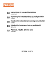
1
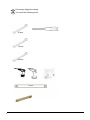
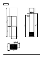
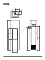
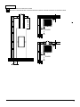
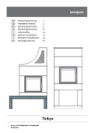
NO
Brukerveiledning2
GB
Installation manual
4
Sakai
Art.no: CC-SAK01-000; CC-SAK03-00; CC-SAK04-000
Certification: 300-ELAB-2025-Sakai-ENI
Last updated: 25.02.2014
!kg
Generell informasjon
Behandling av marmor Rengjør platene med svakt såpevann og fjern alle eventuelle rester av limsøl. Bruk aldri syreholdige/slipende stoffer da disse vil ødelegge både overfate og
polering. Ved rengjøring eller fuging er det viktig å bruke vaskemidler/fug som er godkjent for marmor. Riper i mørk marmor kan farges med blyantbly. Et steinsenter kan være behjelpelig med ulike produkter for overfatebehandling av stein.
Alle våre produkter er testet ihht de seneste
Europanormer i tillegg til NS3058/59 som inkluderer
partikkeltester. Flere Europeiske land har allikevel
lokale lover og regler for installasjon av ildsteder, som
endres regelmessig. Det er kundens ansvar at installasjonen er i henhold til gjeldende lover og regler
hvor ildstedet er montert. Nordpeis AS er ikke ansvarlig
for feilmontering av ildstedet.
Colorado betong
Alle ildsteder kan under noen omstendigheter
bli noe misfarget av røykutslag. Dette kan enkelt
fjernes ved å bruke medfølgende pussesvamp.
For egen sikkerhet, følg monteringsanvisningen. Alle
sikkerhetsavstander er minimumsavstander.
Installasjon av ildsteder må i tillegg være i henhold til
det enkelte lands lover og regler. Nordpeis AS står ikke
ansvarlig for feilmontering av ildstedet.
Tilpasning Tørrstable omrammingen og innsatsen for nøyaktig høyde og posisjon til røykinnføringen i pipen. Bruk vater. Husk at innsatsen ekspanderer under fyring.
Omrammingen må derfor aldri hvile på innsatsen, men
ha en avstand på minimum 3-5 mm over innsatsen og
2 mm under.
Vi tar forbehold om trykkfeil og endringer.
Gulvplate Ildsteder krever en gulvplate foran døren dersom gulvet er av brennbart materiale.
Akryl Medfølgende akryl brukes mellom betongelemetene,
mellom omramming og vegg og i sammenføyninger.
Småskader Grunnet transport og håndtering kan det oppstå små skader på peisen.
Dette kan repareres med akryl/lettsparkel. For perfekt
resultat kan du sparkle og slipe med egnet sparkelmasse. Mindre sår og ujevnheter sparkles. Dersom
såret er dypt eller det er en større skade anbefales det
å sparkle i fere omganger med fiselim eller
sementsparkel for å unngå synk. Jevn til med f.eks. en
fuktig svamp eller et flsebrett.
Sprekker Bygningsmassen rundt peisen kan bevege seg. Spesielt er det i nye hus vanlig at bygningsmassen får betydelige setninger de første årene. I tillegg krymper alle betongelementeri avtagende grad i inntil 15 måneder. Resultatet er at det kan oppstå små sprekker i betong. Bruk peisen i noen måneder. Dersom det
oppstår sprekker, riss opp sprekken med et skrujern
eller lignende (for å gi bedre plass til akryl fugemasse).
Støvsug fatene frie for støv. Sprøyt inn akryl fugemasse og bruk en sparkel eller en såpevåt fnger for å jevne til
massen. Etter et par døgn kan fugen overmales.
Maling Når peisen er ferdig sparklet/slipt og limskjøtene tørre,
er peisen klar til å males. Bruk kun pustende maling (akryl) ment for murverk.
2
NO
NB! Se egen monteringsanvisning for innsatsen
Sakai
Innsats:
X-20F
Stålpipe:
Kan monteres med stålpipe.
Vekt inkludert innsats:
Sakai collorado white / gray concrete 222 kg
Sakai Steel Grate
192 kg
Gulvplate:
Sørg for å følge lokale lover og regler vedrørende
tildekking av brennbart gulv.
Måltegninger (FIG 1A/Sakai = mm)
*Måltegningene angir ca. senter høyde for hull til
røykrøret. Skjevheter i gulv og vegger vil kunne påvirke
målene. Tørrstable ildstedet for nøyaktig høyde og
posisjon til røykinnføringen. Dersom friskluftstilkobling
skal gjennom gulvet, merk av hvor hullet skal være.
Friskluftstilkobling (tilbehør)
NB! Ildstedet kan kun kobles til friskluft gjennom
utsparingene i bunnplaten (se FIG Sakai_mm AIR).
Tett mellomrommet mellom friskluftslangen og
betongen med et ikke-brennbart materiale
(Rockwool etc.).
For ytterligere informasjon se separat monteringsanvisning for friskluftssettet.
Sikkehetsavstander (FIG 2)
Sørg for at angitte minimum sikkerhetsavstander
overholdes. Vær oppmerksom på at disse
avstandskravene kan variere i forskjellige land.
Montering (FIG 3-19)
NO
3
General information
All our products are tested according to the latest
European requirements and also to the Norwegian
standard NS 3058 and NS 3059, which include
particle tests. However, several European countries
have local regulations for installation of fireplaces,
which change regularly. It is the responsibility of the
client that these regulations are complied with in
the country/region where the fireplace is installed.
Nordpeis AS is not responsible for incorrect
installation.
The result is that small cracks may appear in the
concrete/masonry.
Important to check
(please note that this list is not exhaustive):
-distance from firebox to combustible/flammable
materials
-insulation materials/requirements between fireplace
surround and back wall
-size of floor plates in front of fireplace if required
flue connection between firebox and chimney
-insulation requirements if flue passes through a
flammable wall
Painting
When the fireplace has been filled/sanded and the
glued joints are dry, the fireplace is ready to be painted.
Use only breathable paint (acrylic) intended for
masonry.
Adjustment
We recommend to stack the surround without glue in
order to adjust the insert prior to perforating the chimney
for the flue connection. Use a spirit level to ensure that
the surround is mounted straight. The insert will expand
with heat and for this reason the surround must not rest
on the insert. (Above the insert there must be a gap
of 3 to 5 mm. Laterally there is no need for gaps, but
between the lower part of the insert and the surround
there must be a gap of at least 2 mm.)
Floor plate
A fireproof floor plate must be put in front of the fireplace
if the floor is of a combustible material.
Acrylic glue
This is used for gluing the elements towards wall, gluing
the elements together and for filling joints.
Minor damage
The fireplace can sustain minor damage during
transport and handling.
This can be repaired with acrylic/light filler. For perfect
results, you can fill and sand with a suitable filler. Minor
damage and uneven surfaces can be filled. If the
damage is deep or in the event of significant damage,
you are recommended to fill repeatedly with tile
adhesive or cement putty to avoid sinking. Smooth off
with e.g. a damp sponge or a float.
Use the fireplace for a few months. If cracks appear,
scrape them out with a screwdriver or similar (to provide
more space for acrylic joint filler). Vacuum the surfaces
to remove any dust.
Inject acrylic joint filler and even it out with a spatula or
a finger wetted with soapy water.
The joint can be painted after a couple of days
Marble/granite
Clean the plates with mild soapy water and remove any
residue of spilled glue.
Never use acid/abrasive materials, as this will damage
the surface and polishing.
It is important to use detergent/sealant that is approved
for marble for cleaning and sealing.
Scratches in dark marble can be coloured with a pencil.
A professional stone centre can help you with different
products for surface treatment of the stone
Attention!
All stoves and inserts may under certain
circumstances leak some smoke from the door
when opened. Please use the abrasive sponge to
remove any discoloration.
For your own safety, comply with the assembly
instructions. All safety distances are minimum distances.
Installation of the insert must comply with the rules and
regulations of the country where installed. Nordpeis AS
is not responsible for wrongly assembled inserts.
We accept no liability for typographical errors and
changes.
NB! See separate instructions for the insert
Fine fissures
The building material around the fireplace can move.
In new houses in particular, it is common for building
materials to settle substantially in the early years. In
addition, all concrete elements shrink to a decreasing
extent for up to 15 months.
4
GB
Sakai
Insert
X-20F
Steel chimney
Can be connected to steel chimney.
Weight including insert:
Sakai collorado white / gray concrete 222 kg
Sakai Steel Grate
192 kg
Floorplate
Please follow the rules and regulations regarding
floor plates in your country.
Illustration (FIG 1 Sakai=mm)
*The illustration indicates the approximate centre height
of the hole for the flue. Consider possible inclination of
the flue prior to perforating the chimney. Distortions in
floors and walls may influence the height. Dry stack
the fireplace for accurate height and positioning of
the flue/chimney connection. If a fresh air supply set
(accessory) is connected through the floor, mark where
the hole should be.
Fresh air supply (accessory)
ATTENTION! The product can only be connected to
the fresh air supply through the pre cut areas in the
surround (See FIG 1a, Sakai =AIR). Seal off the gap
between the fresh air hose and the concrete with a
non combustible sealant, Rockwool etc
For more information see separate assembly
instructions for fresh air supply.
Safety Distances (FIG 2)
Ensure that the safety distances are complied with.
Please note that these safety distances can vary from
country to country.
Assembly tools - page 4
Appliance dimension & flue gas connections
position (FIG 1a, Sakai =mm)
Air connctions - (FIG 1b, Sakai =mm AIR)
Assembly instructions (FIG 3-19)
GB
5
NO Du trenger følgende verktøy
GB You need the following tools
10 mm
13 mm
24 mm
6
369
195
600
1336
1250
584
1644
FIG 1a
Sakai =mm
290
225
7
FIG 1b
Sakai =mm AIR
225
10
600
225
195
8
1336
1250
1644
584
153
0
290
FIG 2
=Brannmur/ Brandmur/ Palomuuri/ Firewall
50
min.≥ 500
=Brennbart materiale/Brændbart materiale/ Brännbart material/ Tulenarka materiaali/ Combustible material
200
50
R≥600
200
R≥600
200
9
FIG 3
0
60
FIG 3
Legg betongfronten (2 deler) på en ren overflate. For å gjenkjenne det nedre frontelementet, se mål
som illustrert.
.
.
.
Place Front parts of the Sakai Surrounding on a flat surface free from dirt and dust.
Check by measurment position of parts. Arrow shows parts position starting from the bottom.
10
FIG 4
FIG 4A
0
60
FIG 4 & FIG 4A
Plasser stålskinnene på baksiden av frontelementene og kontroller posisjonen (se detalj 4A).
.
.
.
Place steel rails on the back side of the Front of the Surrounding. Check postion of rails.
Detail drawing 4A shows correct bottom position of the rails.
11
FIG 5
FIG 5 B
FIG 5 A
0
27
0
27
0
60
FIG 5
Plasser stålskinnene som vist i FIG 5 (270mm). Fest skinnene til betongdelene med skiver og skruer.
Fest så magnetene på skinnene med skruer (FIG 5B).
.
.
.
Set the rails postion according to the drawing - 270 mm. Fasten rails to the concrete parts
by screws with washers. Assemble initially the magnets on steel the rails - FIG 5B - use screws.
12
FIG 6
FIG 6
Tre stålrørene på gjengestålet som er montert på skinnene (FIG 6). NB! Bruk skiver og muttere.
.
.
.
Assemble joinings beams on threaded pins of the Front - see FIG 6.
Attention! Fasten initially nuts with washers to the rails
.
13
FIG 7
FIG 7
For bakmontering, må utsparingen i bakveggen på omrammingen fjernes, se FIG 7.
NB! Ved bruk av stikksag, benytt diamantbelagt blad da andre blader kan ta skade av materialet.
.
.
.
When appliance is going to be assembled with rear flue gas connection to the chimney, it is necessery to cut a
hole for the chimney connector in the upper part of the back wall. See FIG 7.
Attention!
To cut the hole use a fret saw with diamond covered blades. Due to increased hardness and durability
of concrete normal blades could be insufficient to cut the material.
14
FIG 8
0
27
0
27
FIG 8
Montering av omrammingens bakside: Plasser bakveggen (2 deler) på et flatt og rent underlag.
Plasser stålskinnene på baksiden av elementene og kontroller posisjonen (270mm - se FIG 8). Fest skinnene
med skiver og skruer. Fest magnetene på skinnene med skruer.
.
.
.
Assemble a Back panel of the Surrounding. Place both concrete parts at an even surface free from dirt and
dust. Place steel rails and check proper position - 270 mm. See drawing FIG 8. Fasten screws with washers to
join both concrete parts steel rails together. Assemble initially the magnets on steel the rails.
15
FIG 9
(51,5)*
FIG 9 A
70
FIG 9 B
(103)
220
FIG 9
Plasser bunnelementet på tiltenkt plass. Bruk vater for justering.
NB! Plasser med minimumsavstand fra brennbar vegg som vist i FIG 9B.
Før plassering av innsatsen, juster bena ihht FIG 9A. *Etterjustering kan være nødvendig etter montering av
frontpanelene.
.
.
.
Place Base concrete part at intended place where Appliance is going to be build.
Use Level measuring tool to check if Bottom part lays evenly.
Attention!
Set proper position of the Base concrete part of the Appliance
and set distance to combustible wall - See FIG 9 B.
Before installing the insert on the bottom set the length of the Insert leg according to - FIG 9 A.
(*) The distance is indicative and may need corrections after assmbling the Front Wall.
16
FIG 10
FIG 10
Påfør akryl på frontens kontaktflate mot bunnplaten.
.
.
.
Apply Acryl glue on the lower/ contact side and set the Pre-assembled front on the Base of the Surrounding.
17
FIG 11
FIG 11
Bruk medfølgende profil for å holde fronten på plass under resten av monteringen.
.
.
.
Use Z-profile in order to keep the pre-assembled front in upright position and prevent against its
collapse.
18
FIG 12
r
Ac
yl
FIG 12
Påfør akryl på bakplatens kontaktflate mot bunnplaten.
.
.
.
Apply acrylic glue and place the Pre-assembled back side at the Bottom plate.
19
FIG 13
FIG 13
Fest front- og bakplate sammen med medfølgende stag. Bruk skruer og muttere.
.
.
.
Join the Front and the Back walls of the Surrounding using connecting bars and fasten initially together
using washers and nuts.
20
FIG 14
m
247 m
FIG 14 A
5 mm
m
247 m
FIG 14 B
FIG 14
Kontroller at elementene står i vater. Plasseringen er riktig når rammen på innsatsen stikker 5mm ut i front, se
FIG 14B, og avstanden mellom front- og bakplate er 247mm både i topp og bunn. Gå over skruer og muttere.
.
.
.
Use Level measuring tool in order to set up front and back side of Appliance in upright position.
The Appliance is in right position when the Frame of the insert protrude 5 mm past front surface, see FIG 14B,
and the distance between the Front and the Back is equal 247 mm from the bottom to the top. If these conditions
are met then all joining nuts can be screw tightly.
21
FIG 15
FIG 15
Plasser innsynsskjoldet som vist.
.
.
.
Place the steel part - cover of convection air grate, on the Bottom of the Surrounding.
22
FIG 16
FIG 16
Sakai leveres i tre varianter; Standard betong med betongsider for maling, Colorado betong med Colorado
betongsider og Colorado betong med store siderister.
.
.
.
Sakai surrounding can be delivered with three type of sides. Steel grate side and two concrete versions:
white colorado & gray concrete.
23
FIG 17
FIG 17 A
r
Ac
yl
FIG 17
Monteringa av store siderister;
Påfør akryl på kontaktflatene mellom stålpaneler og stålskinner. Plasser sidepanelene.Stålpanelene er utstyrt med kroker i bunn og topp (FIG 17A).
.
.
.
Assembly of steel grate sides
Apply acrylic glue in contact area between the steel panel and the steel rails.
Place the side steel panel on its place. Steel panel grate is equipped with assembling hooks.
See FIG 17A. Place hooks inside slots of steel rails and lower position of the steel panel.
24
FIG 18
r
Ac
yl
FIG 18
Montering av betongsider
1. Plasser betongsidene, nedre del skal hvile på de L-formede anleggsflatene på stålskinnene (FIG 18B).
2. Juster posisjonen på sideplatene ved hjelp av skruene på monteringsstagene i bunn og topp (FIG 18 A&B).
3. Påfør akryl langs kontaktflatene mellom skinnene og betongsidene.
4. Monter sidene og sett på en midertidig maskeringstape.
.
.
.
Assembly of concrete sides
1. Place initially concrete sides panels on its place. Lower end of the sides rest on L-shaped protrusion of
the steel rails - FIG18B.
2. Set up postion of the sides panels using screws placed on joining beams - see FIG 18 A&B.
3. Apply acrylic glue along the steel rails at contact places with side panels.
4. Assemble side panels on its place. Use painter’s tape to protect concrete sides against collapsing.
25
FIG 19
r
Ac
r
Ac
yl
yl
FIG Z
1
2
FIG 19
Juster magnetene nede i sidene for plassering av sideristene.
Når peisen er ferdig montert, etterfyll skjøtene mellom elementene med akryl og jevn fugen med en såpevåt svamp eller
finger slik at det blir en tydelig fordypning mellom elementene (FIG Z).
.
.
.
Corrrect position of lower steel grate magnets and fasten by the screws. Place the side grates on its place.
Place upper grate on its place. Remove inner lid of the upper grate when appliance assembled to upper flue gas connection.
Once the fireplace is assembled, fill the joints with acrylic and even them out with a sponge or finger and some soapy
water, in order to have a clear indentation between the elements (FIG Z).
26
27
Nordpeis AS, Gjellebekkstubben 11, N-3420 LIERSKOGEN, Norway
www.nordpeis.no