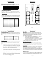
1
EMLINK1
www.emclr.co.uk
User Manual
Issue 1.0
Hardware Description
Emlink1 Programming
Output Channels 1 & 2 - Relay Test
Outputs 1 & 2
The Emlink1 has a build in relay test function. When the output and signal LED’s
5 & 6 are flashing, pressing the right switch will turn on the outputs relay and
signal LED 1.
Both outputs are volt free with normally open, normally closed contacts and are
capable of switching loads of up to 1A @ 30V. Under software control these
outputs can be configured to work in either momentary, toggle or timer mode.
The electrical connections are as follows:
Tamper Output / 3rd Channel - Overview
The tamper channel can work as a tamper relay or a third channel. Pairing the
tamper channel to any local or remote tamper functions automatically configures
the third channel’s output into tamper mode. In tamper mode the relay is permanently energised while no tamper fault has been detected. This is a fail safe system to prevent a power failure not showing a tamper fault. Setting any of the
following will configure the third channel as a tamper channel:
1)
2)
3)
Enable local tamper switch
Enable missing status updates
Pair any remote Emlink1’s tamper channel.
Relay Outputs 1 & 2
Normally Closed (NC)
Common (Com)
Normally Open (NO)
Output 3 / Tamper Relay
Output 3 has volt free contacts and can switch up to 500mA @ 30V. This output
can be configured to work as either a tamper circuit (Energised normally closed)
or a third channel (Normally open) Please refer to the programming section to
configure this output. The electrical connections are as follows:
It is also possible to pair a standard input from a remote Emlink1 to the tamper
channel. A standard input from a remote Emlink1 will not switch the third channel into a tamper channel but it can be used as another tamper input. When a
remote input is being used on a tamper channel, triggering the input will switch
off the tamper relay, i.e. the signal is inverted. This can be a useful feature if you
wish to report back a remote tamper state from a bell box or PIR etc.
If none of the above have been enabled or paired, the tamper relay will work as a
third channel. In this mode the normal state is ‘Normally Open’. The only supported mode for this channel is momentarily.
Note: When the local tamper switch is disabled, its status is still transmitted to
other Emlink1 devices.
Page 17
Tamper / Output 3
Common (Com)
Normally Open (NO)
Power Supplies
The Emlink1 works from a 9 - 24V(Max) DC power supply. The use of a regulated or unregulated DC power supply is permitted providing the voltage does
NOT exceed 24V DC (An unregulated 24V DC power supply will produce a
higher voltage than 24V and will cause damage to the Emlink1). The Emlink1 is
also reverse polarity protected. If using a separate power supply to drive the inputs please ensure the 0V connections are common-ed up
Page 6
Main Menu
1)
2)
3)
4)
5)
Main Menu
Main Features
Description
Hardware Layout
Electrical
Operating voltage
Hardware Description
5)
6)
6)
7)
Inputs
Outputs
Power Supplies
Data Channel
8)
9)
10)
Basic Emlink1 Functions
Status & Signal LED’s
Additional Features
11)
Emlink1 Programming
22)
Specifications
9 - 24V DC (Max)
Operating current (Idle)
25mA (Max)
Operating current (All Relays & LED’s)
85mA (Max)
Relays Max working voltage
30V AC / DC
Relay contact type
Volt Free
Relay 1 & 2 Max current
1A
Relay 3 / tamper relay max current
500mA
Input 1 & 2 voltage
25V (Max)
Input 1 & 2 resistance
11.2K Ohms
Radio
Operating frequencies
433.32 - 434.52MHz
Transmit power
<= 10mW
11) General
12) Data Channel (Pairing and Baud Rate)
13) Data Channel (Parity and Protocol)
14) Inputs 1 & 2 (Tx Pairing Signal and Input Mode)
15) Inputs 1 & 2 (Input to output pairing)
15) Outputs 1 & 2 (Pairing)
16) Outputs 1 & 2 (Operational Modes & Timer Periods)
17) Outputs 1 & 2 (Relay Testing)
17) Tamper / Third Channel (Overview)
18) Tamper / Third Channel (Pairing & Local Tamper Switch)
19) Tamper / Third Channel (Status Update Monitoring)
20) Repeat Mode (Pairing)
20) RF Channel Selection
21) Restore Factory Settings
Radio data Rate
19.04 KHz
Deviation
20KHz (SSB)
Bandwidth
40KHz (SSB)
Specifications
Environmental
Data Channel (Only on certain models)
Interface type
RS232 or RS485
Baud rate
2400 - 19200
Protocols
Emlink, Pelco P & D
Mechanical
Case size without aerial and grommet
115 x 65 x 40mm
Overall size with aerial and grommet
305 x 65 x 40mm
Case rating
IP65
Temperature range
- 10 to + 70 Degrees
Relative humidity
95% non - condensing
Page 1
Page 22
Hardware Description
Emlink1 Programming
RS232 / RS485 Data Channel
Output Channels 1 & 2 - Operational Modes
On certain models of the Emlink1, a data channel with either RS232 or RS485 is
supported. Serial baud rates from 2400 to 19200 are possible with none, odd or
even parity. Supported protocols are: Pelco D & P, Emlink and an open channel.
An easy way to identify between a RS232 or a RS485 version is to look at the last
digit of the units serial number:
The Emlink1 outputs can operate in 3 modes, Momentarily, Toggle or Timer
R:
N:
RS232 Supported
Network RS485 Supported
2)
3)
The electrical connections for both the RS232 and RS485 are listed below:
RS485
1)
RS232
(Rx) Receive Data
(Tx) Transmit Data
(CTS) Clear To Send
B
A
B
A
(RTS) Request To Send
0V
0V
Momentarily means if any paired input is triggered the relay output is
switched on.
Toggle mode will cause its output to flip on detection of any positive
going signal from a paired device.
In timed mode any positive going signal from a paired device will either
start the timer or reset the timer period to the beginning.
Output Mode
Flashing LED’s
Static LED’s
Momentarily
Output x + Signal LED 6
Signal LED 1
Toggle
Output x + Signal LED 6
Signal LED 2
Timer
Output x + Signal LED 6
Signal LED 3
Note: Output x = Output LED 1 or 2
Output Channels 1 & 2 - Timer Periods
Aerial Connector
The Emlink1 allows various time periods per channel from 1 second to 30 minutes. Listed below is the various timer periods.
A threaded M4 connector for mounting of the rubber duck aerial. Please ensure
the aerial has its supplied rubber washer fitted between the case and aerial and
that the aerial is done up hand tight to create a waterproof seal. If the washer is
not fitted or the aerial is loose possible water damage may occur which is not
covered under the product guarantee.
Programming Connector
The programming connector is for firmware upgrades and PC configuration of the
Emlink1. Do not connect anything to this connector other than the recommended
programming tool. Please contact your supplier for purchase information on the
PC configuration / programming tool if required.
Output Mode
Flashing LED’s
Static LED’s
1 Second
Output x + Signal LED 5
Signal LED 1
5 Seconds
Output x + Signal LED 5
Signal LED 2
10 Seconds
Output x + Signal LED 5
Signal LED 3
30 Seconds
Output x + Signal LED 5
Signal LED 4
1 Minute
Output x + Signal LED 5
Signal LED’s 1 & 4
15 Minutes
Output x + Signal LED 5
Signal LED’s 2 & 4
30 Minutes
Output x + Signal LED 5
Signal LED’s 3 & 4
Note: Output x = Output LED 1 or 2
Page 7
Page 16
Emlink1 Programming
Main Features
Restore Factory Settings
This option resets the Emlink1 back to factory default and erases any previously
paired devices. When selected all of the status LED’s will flash together
To reset the Emlink1, hold down the right switch and wait for the signal LED’s to
increment from 1 to 6, this is a warning stating all settings are about to be erased.
When the 6th LED is on there will be a short pause followed by the Emlink1
flashing all its LED’s before rebooting.
Once the Emlink1 has rebooted it will have restored its factory defaults and
erased any previously paired devices.
•
•
•
•
•
•
•
•
•
•
•
•
•
•
•
•
•
•
Repeat mode
7 RF channels
Site Survey mode
Easy Pairing Menu
Encrypted protocol
12 - 24V DC operation
433MHz licence free
Signal Strength Meter
1KM Range (Line of sight)
3 x Volt Free Relay Outputs
2 x Analogue / Digital Inputs
RS232 / RS485 Data Channel
IP65 (All Weather) Rated Enclosure
Momentary, Toggle & Timer outputs
Emlink, Pelco (D & P) and open protocols
Timer outputs from 1 second to 30 minutes
Internal Input to Output Pairing (For timer function)
Missing Status Update Monitoring (Signal Jamming)
Page 21
Page 2
Emlink1 Programming
Basic Functions
Input Channels 1 & 2 - Internal Input To Output Pairing
The Emlink1 has an option to pair its own input to its own output. One good
reason for doing this is to use the Emlink1 as a timer but still transmit its status to
other units. You can only pair input 1 to output 1 or input 2 to output 2.
The option are:
Input / Output Pair
Flashing LED’s
Static LED’s
Input / Output Enabled
Input x + Signal LED 5
Signal LED 1 On
Input ./ Output Disabled
Input x + Signal LED 5
Signal LED 1 Off
Note: Input x = Input 1 or 2
While the Emlink1 is in normal operation the 3 PCB switches have some engineer
friendly features listed below:
Site Survey Mode
This mode sends out a beacon signal every second to assist the engineer in finding an ideal location for installing the Emlink1. You should aim for a minimum of
2 - 3 bars of signal strength for a reliable link.
By pressing switches 1 & 2 together for a brief second the Emlink1 enters ‘Site
Survey’ mode. Site Survey mode only sends out a beacon signal and does not
control any of the Emlink1’s outputs. To exit this mode, again press switches 1 &
2 for a brief second or replace the box cover for 5 seconds.
Output Channels 1 & 2 - Pairing
It is only advisable to enter one unit into site survey mode at any particular time.
In this mode the Emlink1 accepts a pairing signal from another Emlink1. Only
inputs can be paired to an output unless the data channel has been configured for
either the pelco or Emlink protocol. For each new paired device (up to 5 units per
channel) the signal LED’s 1 - 5 increment. Holding down the right switch for
over 3 seconds clears any previously paired devices on the currently selected
output. .
Channel 1 or 2 Input Test
To pair a Pelco Aux command to an output, insure that Pelco is already configured before entering configuration mode. Press the Aux channel you wish to pair
on the Pelco interface and the Emlink1 will learn its address and Aux channel.
Tamper switch
Pair Outputs 1 or 2
Flashing LED’s
Static LED’s
1 device paired
Output x LED only
Signal LED 1
2 devices paired
Output x LED only
Signal LED 2
3 devices paired
Output x LED only
Signal LED 3
4 devices paired
Output x LED only
Signal LED 4
5 devices paired
Output x LED only
Signal LED 5
Holding down either switch 1 or 2 for half a second sends the corresponding
channel ‘ON’ signal. Any receiving device paired to this channel will activate its
corresponding outputs. Again this is useful for a engineer to check a channel is
working correctly.
By holding the tamper switch down for 5 seconds this simulates the box lid being
closed and switches off all of the internal status LED’s. The Emlink1 will also
send a status packet on the tamper switch changing state. There is also a 1 second
delay when you release the tamper switch before the status LED’s become active. Holding down the tamper switch while in configuration mode for 5 seconds
exits configuration mode without saving any new changes.
Note: Output x = Output LED 1 or 2
Page 15
Page 8
Emlink1 Programming
General Description
The Emlink1 is a full featured 433MHz wireless interface designed for short
range transmissions. The heart of the Emlink1 is the XE1205 radio transceiver
which gives the Emlink1 full bi-directional communication for its inputs, outputs,
serial data and repeat functions. Cased in an IP65 rated enclosure the Emlink1 is
designed for indoor and outdoor use.
Each Emlink1 has 2 input channels which can accept either an analogue input
signal from 0 to 24V DC for remote monitoring or a digital signal set by 4 thresholds.
Outputs 1 & 2 are volt free relay contacts and can be configured to work in 3
modes, momentary, toggle and timed outputs with intervals from 1 second to 30
minutes. An option to pair its own input to output allows the Emlink1 to work as
a timer as well as transmitting its status to other paired devices.
The third output can be switched between a tamper relay and a 3rd channel. In
tamper mode the Emlink1 can monitor local and remote tamper switches, lost
status update signal from remote units or report a paired input from a remote unit.
When not used as a tamper circuit the third channel can function as a momentary
volt free output.
Repeat Mode - Pairing
In this mode, briefly pressing the right switch of the Emlink1 transmits a pairing
signal to another device. If the Emlink1 receives a pairing signal from another
device, signal LED 6 will flash twice and the bottom 5 signal LED’s will increment. Holding down the right switch for more than 3 seconds clears any previously paired devices from this channel. When pairing a Emlink1 repeat, all functions from the Emlink1 will be repeated. Up to 5 Emlink1 units can be repeated.
Listed below is the LED states for repeat mode pairing.
Pair Data Channel
Flashing LED’s
Static LED’s
1 device Paired
Input 1 & 2 alternating to Output 1 & 2 LED’s
Signal LED 1
2 devices Paired
Input 1 & 2 alternating to Output 1 & 2 LED’s
Signal LED 2
3 devices Paired
Input 1 & 2 alternating to Output 1 & 2 LED’s
Signal LED 3
4 devices Paired
Input 1 & 2 alternating to Output 1 & 2 LED’s
Signal LED 4
5 devices Paired
Input 1 & 2 alternating to Output 1 & 2 LED’s
Signal LED 5
RF Channel Selection
Other features include a built in signal strength meter, site survey mode for the
engineer to check signal strengths when installing units and a RS232 / RS485
serial interface for transmission of protocols Pelco P & D, Emlink and an open
channel protcol.
The Emlink1 has 7 RF channels and defaults to channel 5. Below is a list of all
the channel numbers and there corresponding frequencies:
RF Channels
Flashing LED’s
Static LED’s
Channel 1 (433.32MHz)
None
Signal LED 1
Channel 2 (433.52MHz)
None
Signal LED 2
Channel 3 (433.72MHz)
None
Signal LED 3
Channel 4 (433.92MHz)
None
Signal LED 3 & 4
Channel 5 (434.12MHz)
None
Signal LED 4
Channel 6 (434.32MHz)
None
Signal LED 5
Channel 7 (434.52MHz)
None
Signal LED 6
Page 20
Page 3
Status / Signal LED’s
Each input / output on the Emlink1 has a closely mounted status LED to indicate
the channel is active. For the signal strength a strip of 6 LED’s is mounted in the
centre at the top of the Emlink1. A brief description of the status / signal LED’s is
listed below:
Signal LED’s
The signal LED’s have 2 meanings, when the display raises from the bottom
upwards this indicates a received signal strength, depending on the receive level
will depend on how many LED’s will light. For a transmission the LED’s will
pulse from the centre outwards.
Emlink1 Programming
Data Channel - Protocol Continued
Listed below is the LED states for the data channel protocol.
Protocol
Flashing LED’s
Static LED’s
Emlink Protocol
Data + Signal LED’s 5 & 6
Signal LED 1
Pelco P & D
Data + Signal LED’s 5 & 6
Signal LED 2
Open Protocol
Data + Signal LED’s 5 & 6
Signal LED 3
Spare
NA
NA
Inputs / Outputs 1 & 2
Input Channels 1 & 2 - Transmit Pairing Signal
The input / output LED’s for channels 1 & 2 flash at half second intervals when a
channel is active.
When input channels 1 or 2 are flashing, The Emlink1 is in “Send Pairing Signal”
mode. By briefly pressing the right button the signal LED’s will flash a TX signal
(Flashing from middle outwards) to send the pairing signal to another Emlink1
device. The receiving device will flash its signal LED 6 to indicate the reception
of this pairing signal.
Channel 3 / Tamper
The status LED flashes at half second intervals providing the tamper fault is local,
if a remote tamper fault has been detected the status LED will pulse twice.
When using this output as a third channel the status LED will only flash at half
second intervals when active.
Data Channel (Data Models Only)
Send Pairing Signal
Flashing LED’s
Static LED’s
Pair Input 1 or 2
Input LED’s 1 or 2
None
Input Channels 1 & 2 - Set Input Mode
The status LED on the data channel emits a short pulse when sending or receiving
data over the RS232 or RS485 port. If the status LED stays on continuously for
half a second or more there is a problem with either the serial port settings or the
protocol used.
Power Saving
During continuous data transmission it will be noticed that the status / signal
LED’s will dim, this is a normal behaviour to save power. The status LED’s will
also extinguish when the tamper switch is held down for more than 5 seconds.
Four possible modes are available (See Hardware Description) and are listed
below:
Input 1 or 2 Mode
Flashing LED’s
Static LED’s
Self Sense N.0.
Input x + Signal LED 6
Signal LED 1
Self Sense N.C.
Input x + Signal LED 6
Signal LED 2
Positive Trig + 9V
Input x + Signal LED 6
Signal LED 3
Positive Trig + 18V
Input x + Signal LED 6
Signal LED 4
Note: Input x = Input LED 1 or 2
Page 9
Page 14
Emlink1 Programming
Hardware Layout
Tamper / Third Channel - Status Update Monitoring
Enable or disable status update monitoring. When enabled any missing status
updates will generate a tamper fault and flash the tamper LED twice.
Tamper + Signal LED 5
Signal LED 2 on
6
5
4
3
2
1
Tamper / Third Channel - Relay Test
The Emlink1 has a build in relay test function. When the tamper and signal
LED’s 5 & 6 are flashing, pressing the right switch will turn on the relay and
signal LED 1.
COM
NC
Status Update Period
6
5
4
3
2
1
1
COM
2
Programming Switches
Static LED’s
Disabled
Tamper + Input 1 & 2 LED’s
All Signal LED’s off
1 Seconds
Tamper + Input 1 & 2 LED’s
Signal LED 1 on
10 Seconds
Tamper + Input 1 & 2 LED’s
Signal LED 2 on
30 Seconds
Tamper + Input 1 & 2 LED’s
Signal LED 3 on
1 Minute
Tamper + Input 1 & 2 LED’s
Signal LED 4 on
TX / A
CTS / B
RTS / A
2 Minute
Tamper + Input 1 & 2 LED’s
Signal LED 5 on
4 Minutes
Tamper + Input 1 & 2 LED’s
Signal LED 6 on
0V
Input2
Flashing LED’s
Tamper
Status Update Period
*RS232 / RS485
RX / B
+V
I/O
Supply
12—24V
0V
Input1
+V
NC
NO
EMLINK1
433MHz Wireless Interface
NO
Enabling the status updates forces the Emlink1 to transmit its status at a given
period even if there are no input changes. If a receiving Emlink1 has its status
update monitoring enabled and there is a loss of signal a tamper fault will be
generated.
Relay 2
Enabled
Signal LED’s
Tamper Relay
Signal LED 1 on
Programming
Connector
Output2
Static LED’s
Tamper + Signal LED 5
Output1
Flashing LED’s
Disabled
Relay 1
Status Update Monitoring
Aerial
Connector
+V
0V
I/O
0V
Tamper
Switch
= Status / Channel LED’s
Page19
* Data channel only on certain models
Page 4
Emlink1 Programming
Additional Features
Data Channel - Set Parity
Status Updates
In this mode, briefly pressing the right switch changes the parity for the RS232 /
RS485 port. The parity must match the other communicating equipment’s parity
to function correctly. Listed below is the LED states for the different parity settings.
When an Emlink1’s inputs change it automatically transmits an status update.
This is a normal procedure but if the inputs do not change for a while the receiver
does not know if the transmitter is still functioning correctly. To overcome this
the Emlink1 can be programmed to transmit a status update at a given period.
Status updates have 2 main functions:
Parity
Flashing LED’s
Static LED’s
None
Data + Signal LED 5
Signal LED 1
Even
Data + Signal LED 5
Signal LED 2
Odd
Data + Signal LED 5
Signal LED 3
1)
2)
If a receiver becomes out of sync with the transmitter i.e. a power cut,
receiving automatic status updates will re-sync the receiver.
The receiver can also be programmed to detect missing status updates, if
2 or more status updates are missing the receiver generates a tamper fault
and the tamper LED will flash twice to indicate a remote tamper fault.
Data Channel -Protocol
To enable status updates please refer to the programming section.
In this mode, briefly pressing the right switch changes the selected protocol for
the RS232 / RS485 port. Currently 3 protocols are available which are listed
below:
Input channels analogue updates
1)
Emlink protocol. This protocol is used for outputting all paired devices
radio transmissions over either RS232 or RS485 port. It is also possible
to control a paired Emlink1’s outputs via this protocol. Typical uses for
this is protocol are expander modules (Extra I/O channels) Reading of an
Emlink1’s analogue input voltages, status monitoring in software, door
access control etc. Please refer to the programming guide.
2)
Pelco P & D protocol. This is mainly used for CCTV telemetry. The
Emlink1 automatically detects Pelco P or D and has built in support to
pair Pelco AUX commands to any of the Emlink1’s 3 outputs (See
programming section).
3)
Open protocol. This protocol has no input filtering and will transmit any
data sent through the RS232 or RS485 lines. Care needs to be taken with
the hardware connections to prevent the Emlink1 permanently transmitting data because of poorly connected cables. It is advisable to use the
above protocols (Emlink & Pelco) if possible.
Page 13
When an Emlink1 transmits a status update it measures the input voltages and
transmits this level as a digital value in 0.1V steps. The purpose of this feature is
for remote data logging etc and has no affect on the inputs previously described.
Repeat Function
An Emlink1 can repeat other Emlink1’s signals. The repeating Emlink1 still can
use its own inputs and outputs while repeating other units. For an Emlink1 to
repeat another units data it physically has to receive the first transmission and
then re-transmit this on the same frequency. This is perfectly ok for status updates
but for the data channel if a high data through put is required we cannot guarantee
its operation.
RF Channel Selection
7 RF channel channels are available in the 433 - 434MHz band. All Emlink1 units
must be on the same channel for them to communicate. If a particular channel is
found to be poor it is advisable to try another channel
Page 10
Hardware Description
Emlink1 Programming
Inputs 1 & 2
Tamper / Third Channel -Pairing
Listed below are the 4 modes of operation for Inputs 1 & 2:
In this mode, briefly pressing the right switch of the Emlink1 transmits a pairing
signal to another device. If the Emlink1 receives a pairing signal from another
device, signal LED6 will flash twice and the bottom 5 signal LED’s will increment by 1. Holding down the right switch for more than 3 seconds clears any
previously paired devices from this channel. It is only possible to pair a data
channel with another data channel. Listed below is the LED states for the data
channel pairing.
Mode 1 - Self Sensing Normally Open Input
In this mode the Emlink1 outputs a sensing pulse to check to see if there is a open
or short circuit present. Idle state would be represented by an open circuit where
an active state would represented by a short circuit. Typical examples would be a
open collector output from an alarm panel etc.
Pair Data Channel
Normally Closed - Active State
Flashing LED’s
Static LED’s
Normally Open - Idle State
+V
+V
0V
0V
Mode 2 - Self Sensing Normally Closed Input
In this mode the Emlink1 outputs a sensing pulse to check to see if there is a open
or short circuit present. Idle state would be represented by an short circuit where
an active state would represented by a open circuit. Typical examples would be a
magnetic door contact or a PIR sensor
Normally Closed - Idle State
Normally Open - Active State
+V
+V
0V
0V
Modes 3 & 4 - Positive Trigger (either 9 or 18 volts)
1 device paired
Tamper LED only
Signal LED 1
2 devices paired
Tamper LED only
Signal LED 2
3 devices paired
Tamper LED only
Signal LED 3
4 devices paired
Tamper LED only
Signal LED 4
5 devices paired
Tamper LED only
Signal LED 5
Tamper / Third Channel - Local Tamper Switch
Enable or disable local tamper switch. This does not affect the local switches
state being transmitted to other Emlink1 interfaces. The options are as follows:
Tamper Switch
Flashing LED’s
Static LED’s
Disabled
Tamper + Signal LED 6
Signal LED 1 on
Enabled
Tamper + Signal LED 6
Signal LED 2 on
Modes 3 & 4 accept positive voltages from 0 to 24V DC from an external source.
For digital switching, voltages over 9V (Mode3) or 18V(Mode 4) switch the
Emlink1 into an active (triggered) state.
Page 5
Page 18
Emlink1 Programming
Emlink1 Programming
The Emlink1 is configured by a software menu system using the status and signal
LED’s to show the currently selected options. When in configuration mode the
currently selected option is shown by 1 or more LED’s pulsing twice and the
currently selected parameter is shown by one or more of the signal LED’s 1 - 4.
To Enter configuration mode hold down switches 1 & 2 for 3 seconds. Once 3
seconds has elapsed all of the Emlink1’s LED’s will flash 3 times. Depending if
you are using a data or non data unit the first option will be the data channel or
the input1 channel. For this manual we will assume a data unit is being used.
Data Channel - Pairing
In this mode, briefly pressing the right switch of the Emlink1 transmits a pairing
signal to another device. If the Emlink1 receives a pairing signal from another
device, signal LED6 will flash twice and the bottom 5 signal LED’s will increment by 1. Holding down the right switch for more than 3 seconds clears any
previously paired devices from this channel. It is only possible to pair a data
channel with another data channel. Listed below is the LED states for the data
channel pairing.
While in configuration mode, switches 1 - 3 work as follows:
•
•
•
•
Switch 1 changes the current menu’s option
Switch 2 changes the currently selected parameter
Pressing switch 1 for 3 seconds will save all new settings, flash all of the
Emlink1 LED’s twice and reboot the system.
Pressing the tamper switch for 5 seconds exits configuration mode and
switches off all LED’s without saving new settings.
Pairing an Input to an output
To pair an input to an output is as follows:
1.
2.
3.
4.
5.
6.
5.
Place both Emlink1’s in configuration mode
Select an output channel to pair (1st Emlink1)
Select an input channel you wish to pair from (2nd Emlink1)
On the 2nd Emlink1 press the right button. The 1st Emlink1’s signal
LED 6 should flash twice and the signal LED’s 1 - 5 should increment.
Save configuration by holding down switch 1 for 3 seconds
Test the connection by pressing the input channel switch for half a
second and make sure the second box responds.
Pairing complete!
Page 11
Pair Data Channel
Flashing LED’s
Static LED’s
1 device paired
Data LED only
Signal LED 1
2 devices paired
Data LED only
Signal LED 2
3 devices paired
Data LED only
Signal LED 3
4 devices paired
Data LED only
Signal LED 4
5 devices paired
Data LED only
Signal LED 5
Data Channel - Set Baud Rate
In this mode, briefly pressing the right switch changes the baud rate from 2400 to
19200 for the RS232 / RS485 port. The baud rate must match the other communicating equipment’s baud rate to function correctly. Listed below is the LED states
for the different baud rates.
Baud Rate
Flashing LED’s
Static LED’s
2400 Baud
Data + Signal LED 6
Signal LED 1
4800 Baud
Data + Signal LED 6
Signal LED 2
9600 Baud
Data + Signal LED 6
Signal LED 3
19200 Baud
Data + Signal LED 6
Signal LED 4
Page 12