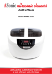
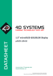
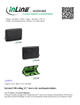
1
Use and installation Manual Stromboli digital Electric radiators with heat transfer fluid Index Presentation .......................................................................................................1 The Advantage ..................................................................................................1 Function...............................................................................................................3 Safety regulations.............................................................................................10 Preaparation for istallation ..............................................................................10 Fastening the wall brackets.......,.....................................................................11 Electrical connections and supply ..................................................................14 Troubleshooting.................................................................................................14 Range and dimensions ....................................................................................15 Technical characteristics .................................................................................16 1 P r e s e n tat i o n The STROMBOLI DIGITAL radiator flaunts an elegant, dynamic design whilst guaranteeing very high thermal power. This radiator has been designed in accordance with standard UNI EN 442 to ensure low energy consumption due to the highly conductive aluminium, and a long life thanks to the materials used, the two coats of anaphora and the epoxy polyester paint in RAL 9010 covering all surfaces. Electronic thermostat with 6-order pilot wire: stop, antifreeze, comfort, eco. -- Class II electrical resistance -- : Device in conformity with European Directive 2002/96/CE (DEEE). -- : Do not cover the heating device. T h e A dva n tag e s - The comfort of central heating: its design using heat transfer fluid guarantees gentle heating and a constant temperature. - Aluminium heating elements: optimises heat diffusion ALSTDIGV058004FB / ALSTDIGV058006FB / ALSTDIGV058008FB / ALSTDIGV058009FB / ALSTDIGV058011FB 12/10/2010 2 T h e A dva n tag e s - A neat design: The perfect finish of the epoxy painted steel radiator and half maximum control unit result in a product with an exclusive, sober design. Adapts easily to suit all interior decor styles. - Overheating protection: The radiators are fitted with a built-in temperature limiter to protect the appliance from overheating. - Tilting protection: Fixed wall bracket installation system. Function Presentation display Mode/Prog + ON/OFF 3 Function Functioning feature t Keyboard function The keyboard is composed by four button: è One adjustment button + , è One adjustment button - , è One ON/OFF button (ON/OFF) , è One mode selection button (Mode) . - Pressing the + button allows to set the desired temperature. - Pressing the - button allows to set the desired temperature. - Pressing the button allows to switch On/ Off the thermostat / radiator. - Pressing the mode button allows to choose the mode of functioning: COMFORT, ECONOMY, FROST PROTECTION or automatic mode with the central programmer. When the thermostat is in the Mode ON, the LCD module displays: - The set temperature. - The « flame » symbol if the output status is ON - The current Mode on the right of display - The program profile (the bar graph) Ex: Display in mode COMFORT Ex : Display in mode OFF t Set temperature displaying. No measured temperature displaying. - Pressing briefly the + or the - button, increases or decreases the set temperature by steps of 0,5°C. - Pressing longer than one second the + or the - button allows continues increasing/ decreasing the set temperature by steps of 0,5°C each 250 ms. - The set temperature is saved in the memory t Set temperature adjustment: - The COMFORT temperature settings are adjustable by steps of 0,5°C 4 Function 3.1.2. Configuration The CONFIGURATION menu allows adjusting the way of functioning of the thermostat following the user’s requests. - To enter to the CONFIGURATION Menu, press and hold the ON/OFF button for 5 seconds. - To confirm the modification or to switch to the next setting, press shortly again the MODE button. After 120 seconds without action, the thermostat will exit automatically from the “configuration” menu and will come back to the previous mode. After entering to this menu the thermostat displays: è The value of the set- back in ECONOMY mode. The pointer (on the left of display) is on the 1st position (vertical scale from 1 to 7) and the current value of set-back is displayed. Example : The modifications are done by the + button for increasing and the - button for decreasing. The possible modifications are: from « --- » then 0.5°C to 10°C by steps of 0,5°C (the value will be saved in the memory). Original value is: 3,5°C. If you choose « --- » : it corresponds with the adjustable ECONOMY temperature (by the user). The set-back will be calculated on the base of the value of CONFORT and ECONOMY set temperatures. If you choose the set-back value from 0.5° to 10°, the ECONOMY set temperature is not adjustable and the set-back will be deduct from the COMFORT temperature. è Correcting the room temperature measurement by the user. The pointer (on the left of display) is on the 2nd position. You can change the temperature measurement by up to + or - 5°C: by steps of 0.1°C. Originally: no temperature correction. Press + button to increase, or the - button to decrease to temperature correction. Example of correction of – 1,5°C. è Configuration of the backlight The back-light displaying time is adjustable by steps of 15 seconds from 0 to 225 seconds. Adjusting by the + or - buttons. To confirm press the ON/OFF button. If the choice = 0, no back-light ! Example : 5 Function è The frost Protection value. This can be modified from 5 ºC to 15 ºC by steps of 0.5 ºC (the value is stored in memory). By default: 7 ºC. The indication of this choice is shown with the highlighting of the number 3 located on the left-hand side of the display (vertically numbered from 1 to 7) and the frost Protection value being shown to a tenth of a degree. è Exit from the configuration mode Functioning of the mode button t Choose the mode of fonctionning Mode - Pressing briefly the MODE button allows to choose the mode of fonctionning; - The bar graph shows the chosen mode. The symbols on the right of display indicate the real current mode. With exception of application with the central programmer both of them should indicate the same mode. Pressing briefly Mode Pressing briefly Mode Pressing briefly Mode Permanently COMFORT mode. The COMFORT set temperature displaying. Pressing briefly or longer the + or - button allows to modify the COMFORT set temperature from 5 to 30°C. Note: In application with the central programmer the symbols or can be displayed on the place of . This indicates that the load shedding is on. Permanently ECONOMY mode. The ECONOMY set temperature displaying. In the case of adjustable ECONOMY temperature (see the CONFIGURATION Menu), pressing briefly the + or button allows to modify the ECONOMY set temperature from 0 to the CONFORT set temperature. Permanently FROST PROTECTION mode. The FROST PROTECTION set temperature displaying. Note: Idem COMFORT mode. Central Mode.. Displaying the set temperature following the current program received by the pilot wire input or the PLC input. 6 Function t Creating a local program A long press on the «Mode/Prog» button (about 5 seconds) is used to enter the program creation for: è Creating of a comfort program and eco program. This mode is used to view the schedules stored in the EEPROM, shown with the «ProG» message displayed on the four digits of display, as well as with an indication of the day number (from 1 to 7). è Setting the calendar time Moving from one step to the next in this process is done by pressing the «Mode/Prog» button. The schedule is entered by using the - button to select the eco periods, and pressing on the + button to select the comfort periods. The selecting of this mode is visualised by displaying the bar graph, stored in the user memory block, N1 / P1, flashing every 0.5s (starting from midnight). The setting’s position is indicated with the corresponding icon, flashing at the same speed as the bar graph. Each position corresponds to a period of one hour. If no keys are pressed for 120 seconds, the thermostat will return to normal operating mode with the new programme stored in the memory. The settings are made on day by day. Moving from one day to the next is made by pressing on the «Mode/Prog» button, and the current day being programmed is indicated on the left hand side of the display. Note - The default programme is: Comfort mode from 6 am to 10 pm (eco mode from 10 pm to 6 am) t Copying a program. It is possible to copy the program of the previous day. To copy the program from the previous day, just change the day by pressing on the «Mode/Prog» button, during at least 3 seconds. As soon as the 3 seconds have passed, the displayed program, stored in the memory, will be replaced by the program for the previous day. t Time setting mode When the microcontroller is reset, the time shown will be 00:00. This is the current time. To set the correct time (day, hour, minute), use the + button to increase the value, the - button to decrease the value, and the «Mode/Prog» button to move from one day to the next. When pressing on either the + or - buttons, the flashing of the two middle dots will be stop. If you stop to press buttons more three seconds, the flashing of the two central dots going restart. The first thing to do is set the day. The number icons 1 through 7 will flash in turn. After that, the hours and minutes need to be set. The first thing to do is set the day. The number icons 1 through 7 will flash in turn. After that, the hours and minutes need to be set. A long press on the + or - button, increasing or decreasing of one minute the setting clock, after 7 Function a period of about 750ms, it activates a sequence of 30 increments or decrements at intervals of 180 to 200ms (semi fast speed). Once these 30 steps made, it increments or decrements the tens of minutes (fast speed). When the button is released, the time setting will stop. The time setting can be fine tuned again by restarting the same procedure. Press the «Mode/Prog» button to return to normal operation. The thermostat can also use local programming. In this case, it overrides the central programming (TAP), with the exception of the frost protection order and the stop order. Operating with a PW or radio (RF) programmer The thermostat can also use local programming. In this case, it overrides the central programming (TAP), with the exception of the frost Protection order and the stop order. Position Pilot wire Mode OFF RF X2D mode OFF FROST PROTECTION ECONOMY OFF COMFORT - 2°C COMFORT - 1°C COMFORT OFF Local program Frost protection Local program ECONOMY Local program COMFORT Level without local program (with a control unit) OFF OFF OFF OFF OFF FROST PROTECTION ECONOMY FROST PROTECTION OFF COMFORT - 2°C COMFORT - 1°C COMFORT OFF FROST PROTECTION FROST PROTECTION FROST PROTECTION FROST PROTECTION FROST PROTECTION OFF FROST PROTECTION FROST PROTECTION FROST PROTECTION FROST PROTECTION FROST PROTECTION OFF FROST PROTECTION FROST PROTECTION FROST PROTECTION FROST PROTECTION FROST PROTECTION OFF FROST PROTECTION FROST PROTECTION FROST PROTECTION FROST PROTECTION FROST PROTECTION ECONOMY OFF FROST PROTECTION ECONOMY OFF COMFORT - 2°C COMFORT - 1°C COMFORT OFF FROST PROTECTION FROST PROTECTION FROST PROTECTION FROST PROTECTION FROST PROTECTION OFF FROST PROTECTION ECONOMY ECONOMY ECONOMY ECONOMY OFF FROST PROTECTION COMFORT COMFORT COMFORT COMFORT OFF FROST PROTECTION ECONOMY ECONOMY ECONOMY ECONOMY COMFORT - 2°C OFF FROST PROTECTION ECONOMY OFF COMFORT - 2°C COMFORT - 1°C COMFORT OFF FROST PROTECTION FROST PROTECTION FROST PROTECTION FROST PROTECTION FROST PROTECTION OFF FROST PROTECTION ECONOMY ECONOMY ECONOMY ECONOMY OFF FROST PROTECTION COMFORT COMFORT COMFORT COMFORT OFF FROST PROTECTION ECONOMY COMFORT - 2°C COMFORT - 2°C COMFORT - 2°C COMFORT - 1°C OFF FROST PROTECTION ECONOMY OFF COMFORT - 2°C COMFORT - 1°C COMFORT OFF FROST PROTECTION FROST PROTECTION FROST PROTECTION FROST PROTECTION FROST PROTECTION OFF FROST PROTECTION ECONOMY ECONOMY ECONOMY ECONOMY OFF FROST PROTECTION COMFORT COMFORT COMFORT COMFORT OFF FROST PROTECTION ECONOMY COMFORT - 2°C COMFORT - 1°C COMFORT - 1°C COMFORT OFF FROST PROTECTION ECONOMY OFF COMFORT - 2°C COMFORT - 1°C COMFORT OFF FROST PROTECTION FROST PROTECTION FROST PROTECTION FROST PROTECTION FROST PROTECTION OFF FROST PROTECTION ECONOMY ECONOMY ECONOMY ECONOMY OFF FROST PROTECTION COMFORT COMFORT COMFORT COMFORT OFF FROST PROTECTION ECONOMY COMFORT - 2°C COMFORT - 1°C COMFORT 8 Function t Viewing the operating mode The displaying of the operating mode will be done with the help of pictograms comfort, eco, frost protection and stop. Only the currently active mode is visible. This is either: Comfort, comfort (-1) and comfort (-2) mode Economy mode Frost protection mode Off (central unit) or load shedding (PW); stop mode is not displayed during RF load shedding t Keypad lock When the device is in normal operating mode (displaying the temperature), simultaneously pressing on the + and - buttons for 4 seconds, the keypad is locked. Once that was done, each time you press any button, «bloc» appears on the display. To unlock the device, press and hold the buttons + and - again for 4 seconds. NOTE: a RESET (after a power off) cancels the keypad lock. 9 Safet y r e g u l at i o n s Should damages be caused from breach of these regulations, the manufacturer’s guarantee shall be invalidated. -- Do not use the appliance outdoors. - Your appliance is intended for domestic use. It may not be used for other purposes. - If the appliance has been dropped, has been damaged or does not function correctly, do not use it and ensure that the appliance power supply has been disconnected (fuse or switch). - Do not dismantle the appliance. A poorly-repaired appliance can cause risks for the user. - Contact your retailer for any problem. - If the power lead has been damaged, it must be replaced by the manufacturer, after-sales service or another professional to avoid all danger. - This heating appliance is filled with a specific quantity of special oil. The safety sheet for this is available on request. In the event of a leak, turn the appliance off and close it to prevent the oil from being dispersed or accidentally ingested by a child. Then contact the appliance retailer or manufacturer’s representative. Any operation involving the opening of one of the two stoppers holding the oil in, must be carried out by an authorised manufacturer’s representative. - When disposing of the heating appliance, comply with regulations on oil disposal. - Warning: do not cover the appliance – danger of overheating. If the appliance is covered, the rise in temperature will cause the interior limiter to intervene. - This appliance is not suitable for use by people (including children) with reduced physical, sensory or mental capacities, or by people without specific experience and knowledge, without prejudice to their being able to make use, through a person responsible for their safety, of monitoring or preliminary instructions on the appliance use. - Children should be monitored to ensure that they do not play with the appliance. Before connecting the radiator, disconnect the power supply using the general switch. This radiator is a class II appliance. As such, it may be installed in all rooms of the house, except for volumes 1,2,3 of a bathroom (IP20). The heating appliance must be installed in such a way that the switches and other control devices cannot be touched by someone in the bath or shower (in compliance with standard NF C15-100). The radiator must not be installed beneath a socket. The radiator must be installed at least 15 cm away from all obstacles (shelves, curtains, furniture, etc.). The power circuit of this appliance must include an all-pole circuit breaking device (in compliance with standard NF C15-100). Volume 3 Volume 2 60 cm 60 cm Volume 1 300 cm i n sta l l at i o n fo r 225 cm P r e pa r at i o n 60 cm Control panel 10 P r e pa r at i o n i n sta l l at i o n fo r min. 150 mm 10 ma 0 x. m m 1 m 15 in. 0m m n. mi m 0m 50 m 15 in. 0m m min. 120 mm CORRECT INSTALLATION 2 m 15 in. 0m m n. mi m 0m 0 5 m 15 in. 0m m 11 F a st e n i n g the wa l l b r ac k e t s 1- Before fixing the radiator to the wall, check that the distances stated on figures 1 and 2 (see previous page) are respected. 2- Use the table above to determine your radiator model and respect the heights and width specified for installing the fixing brackets. To make installation easier, refer to figures 3 and 4 (see next page). 3- All our radiators are fitted with four (2 at the top: right and left; 2 at the bottom: right and left) fixing notches according to the power of the model chosen. 4- Fix the brackets to the wall using wall plugs (not supplied) suitable for the wall structure onto which the radiator is to be installed. 5- Once fixed, screw the safety system into place as shown in figure 5 (see next page) References Power ALSTDIGV058004FB ALSTDIGV058006FB ALSTDIGV058008FB ALSTDIGV058009FB ALSTDIGV058011FB 500 W 750 W 1000 W 1250 W 1500 W H= Height of fixing holes in mm 500 500 500 500 500 L = Width of fixing holes mm 130 290 370 370 690 A = Height above ground mm 130 130 130 130 130 3 min. 120 mm A H L 12 F a st e n i n g the wa l l b r ac k e t s 4 20 mm A 5 B 13 Electrical a n d s u pp ly connections - In accordance with current regulations, the radiator power supply must be protected by a 30 mA circuit breaker calibrated to 16 A. - Before using the appliance the first time, check that the voltage used corresponds to that specified on the appliance. - This radiator is a class II appliance (double electrical insulation). Earth connection is prohibited. - Connection of the three wires must take place in an electrical junction box compliant with current regulations. ELECTRICAL CONNECTION Single-phase power supply 230 V~ +10 % -10 % 50Hz. The pilot wire must be disconnected if not in use. - Blue wire: neutral - Brown wire: live - Black wire: pilot wire T ro u b l e s h o ot i n g None of the lights turn on. - Check the position of the switch/power supply protection fuse on the electric panel. Room temperature is not high enough, the appliance does not heat sufficiently. - The heating may be set to Eco, Antifreeze or Stand-by, or on Automatic mode with a low temperature set by the programmer or energy management system. Change to Permanent Comfort mode or increase the temperature set. Many situations may give rise to a slight metallic crackle. - The appliance was fixed to an irregular wall. - The appliance was fixed to a non-insulated wall. - The appliance is in a current of cold air. - The appliance is positioned incorrectly on the brackets. - The appliance is heating or there is a sudden change in temperature Should the problem continue, contact the after-sales service. 14 Range and dimensions References Power Height in mm Depth in mm Width in mm Number of elements ALSTDIGV058004FB 500 W 577 100 430 4 ALSTDIGV058006FB 750 W 577 100 590 6 ALSTDIGV058008FB 1000 W 577 100 750 8 ALSTDIGV058009FB 1250 W 577 100 830 9 ALSTDIGV058011FB 1500 W 577 100 990 11 Thickness Height Width 15 Technical c h a r ac t e r i st i c s - Power supply: 230V AC +10% -10% 50 Hz. - Safety: Class II according to EN60335 - Environment: IP20 - Operating temperature: from 0°C to +40°C. - Storage temperature: from -20 °C to +70 °C. - Built-in proportional electronic regulation, supplied by TRIAC with 6-order pilot wire. - Temperature adjustment from 7°C to 30°C. Manufacturer: DELTACALOR The symbol on the product indicates the obligation to dispose of it, at the end of its working life, with a specialised collection centre, in compliance with Directive WEEE 2002/96/EC. Should you choose to replace it, you may return the old appliance to the distributor. This product is not ordinary household waste. By disposing of the product appropriately at the end of its working life, we can protect the environment and limit use of its natural resources. Declaration of conformity: We hereby declare, under our own responsibility, that the products presented in these instructions comply with all basic requirements of the Low Voltage Directives 2006/95/EC and EMC 2004/108/EC and RoHS 2002/95/EC. They have been manufactured in accordance with processes certified ISO 9001 V2000. 16 N ot e s 17 N ot e s 18 DELTACALOR s.r.l. Via Mazzini 23801 – Calolziocorte – Lecco Italy www.deltacalor.com