1
INSTALLATION MANUAL
Wireless remote controller kit
BRC7FA532F
1
1
2
1x
1x
3
1x
4
2x
5
2x
6
2x
7
1x
8
1x
9
1x
2
2
2
1
1
1
10
2x
3
3
3
1
2
X24A
(BLK)
2
7
6
5
4
1
8
9
3
3
2
2
3
ON
4
OFF
TEMP
TIME
A
SETTING
ON
3
UP
FAN
TEMP
TIME
A
B
DOWN
B
RESERVE CANCEL
C
TIMER
6
SETTING
2
3
4
UP
FAN
2
1
OFF
DOWN
4
RESERVE CANCEL
4
MODE
C
TIMER
D
MODE
SWING
5
4
2
3
5
SWING
1
/TEST
/TEST
5
3
1,6
2
4
5
1
5
2
3
6
8
7
3
6
BRC7FA532F
CONTENTS
Installation manual
Wireless remote controller kit
Page
Meaning of caution symbols
Safety considerations .....................................................1
Before installation ...........................................................1
Failure to observe these instructions
properly may result in property damage or
personal injury.
Accessories ...................................................................1
Note to the installer .......................................................1
Remote controller installation .........................................2
Installing the wireless remote controller ........................2
Determination of address and MAIN/SUB remote
controller........................................................................2
Setting procedure ..........................................................2
Installation of the transmitter board ...............................3
Installation of the decoration panel................................4
Installation of the receiver .............................................4
Field setting ....................................................................4
Test operation .................................................................5
READ THIS MANUAL ATTENTIVELY BEFORE
STARTING UP THE UNIT. DO NOT THROW IT
AWAY. KEEP IT IN YOUR FILES FOR FUTURE
REFERENCE.
IMPROPER INSTALLATION OR ATTACHMENT
OF EQUIPMENT OR ACCESSORIES COULD
RESULT IN ELECTRIC SHOCK, SHORTCIRCUIT, LEAKS, FIRE OR OTHER DAMAGE
TO THE EQUIPMENT. BE SURE ONLY TO USE
ACCESSORIES MADE BY DAIKIN WHICH ARE
SPECIFICALLY DESIGNED FOR USE WITH
THE EQUIPMENT AND HAVE THEM
INSTALLED BY A PROFESSIONAL.
IF UNSURE OF INSTALLATION PROCEDURES
OR USE, ALWAYS CONTACT YOUR DAIKIN
DEALER FOR ADVICE AND INFORMATION.
The English text is the original instruction. Other
languages are translations of the original instructions.
Information classified as NOTE contains instructions to
ensure proper use of the equipment.
■ Refer also to the installation manual
supplied with the indoor unit and the
installation manual supplied with the
decoration panel.
■ There is only 1 possible installation
position of this kit into the decoration panel.
It is therefore recommended that
installation orientation of the decoration
panel is confirmed prior to installation of
this kit.
• Ensure that nothing interrupts
operation of the wireless remote
controller.
• Ensure that the signal from the
remote controller can easily be
transmitted.
• Ensure that the operation display
lamp and other indicator lamps can
easily be seen.
• Ensure that there is neither a source
of light nor a fluorescent lamp near
the receiver.
• Ensure that the receiver is not
exposed to direct sunlight.
BEFORE INSTALLATION
Accessories
SAFETY CONSIDERATIONS
Please read this "Safety considerations" carefully before
installing air conditioning equipment and be sure to
install it correctly. After completing the installation, make
sure at start up operation that the unit operates properly.
Please instruct the customer how to operate the unit and
how to perform maintenance.
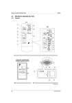
See figure 1. Check if the following accessories are
included with your kit.
1 Receiver
2 Wireless remote
controller
3 Remote controller
holder
4 Screw
for installing
remote controller
holder
5
Alkaline battery
of type AAA.LR03
6
Tapping screw
for transmitter board
7
8
9
10
Clamp
Transmitter board
Unit No. label
Installation manual
Operation manual
Note to the installer
Be sure to instruct the customer how to properly operate
the system showing him/her the supplied operation
manual.
BRC7FA532F
Wireless remote controller kit
Installation manual
4PW72924-1 – 01.2012
1
REMOTE CONTROLLER INSTALLATION
Setting procedure
Installing the wireless remote controller
Setting the receiver
■ Do not throw the remote controller or subject it to
powerful shocks and do not store the remote
controller where it may be exposed to moisture or
direct sunlight.
■ When operating, point the transmitting part of the
remote controller in the direction of the receiver.
■ The direct transmitting distance of the remote
controller is approximately 7 meters.
■ The signal cannot be transmitted if something such
as curtains blocks the receiver and the remote
controller.
Installing to a wall or a pillar
1 Fix the remote controller holder
with the supplied screws.
2 Slide the remote controller into the
remote controller holder from the
top.
(2)
Set the wireless address switch (SS2) on the transmitter
board according to the table below.
Unit No.
1
2
3
1
2
3
3
3
2
2
1
1
Wireless address switch
(SS2)
When using both a wired and a wireless remote
controller for 1 indoor unit, the wired controller should be
set to MAIN. Therefore, set the MAIN/SUB switch (SS1)
of the transmitter board to SUB.
MAIN
SUB
S
M S
M
MAIN/SUB switch (SS1)
Setting the address of the wireless remote controller
(1)
A
B
C
How to insert the batteries
1 Open the back cover of
the remote controller by
sliding it in the direction
of the arrow.
2
(See figure 3)
Field Set mode
Address (is factory set to "1")
Display setting
Setting from the remote controller
Insert the attached dry
cell batteries. Properly
insert
batteries
by
matching the (+) and (–)
polarity
marks
as
indicated. Then close the
cover as before.
1
Hold down the
button and the
button for
at least 4 seconds to enter the Field Set mode.
(Indicated in the display area in the figure.)
2
Press the
button and select an appropriate
display setting (a/b). Each time the button is pressed
the display switches between "a" and "b". Refer to
"Display setting a/b" on page 3 for full comprehension
of this feature.
3
Press the
button and
button to set the address.
Determination of address and MAIN/SUB
remote controller
■ If setting multiple wireless remote controllers to
operate in one room, perform address setting for the
receiver and the wireless remote controller.
■ If setting multiple wired remote controllers in one
room, change the MAIN/SUB switch of the receiver.
Address can be set from 1 to 6, but set it to 1~3 and
to same address as the receiver. (The receiver does
not work with address 4~6.)
4
Press the
5
Hold down the
button for at least 1 second
to quit the Field Set mode and to return to normal
display again.
Installation manual
2
4PW72924-1 – 01.2012
button to confirm the setting.
BRC7FA532F
Wireless remote controller kit
Display setting a/b
Affix the unit number label
The wireless remote controller has 2 possible display
settings.
Affix corresponding unit number labels onto both air
outlet of the decoration panel and onto back of the
wireless remote controller.
The standard setting a permanently indicates all
operational items whereas the multi system display
setting b indicates operations for a limited period of time
after execution of settings only.
In case the target indoor unit is simultaneously being
controlled;
■ by another unit in group control,
■ by a wired remote controller,
■ by a centralized remote controller.
the indoor unit sometimes does not respond to ON/OFF
and temperature setting commands from the wireless
remote controller.
In order not to confuse the customer with possible
discrepancies between the wireless remote controller
display and the actual operation state of the indoor unit, it
is recommended to set the display on the wireless
remote controller to b in such a control configuration.
Check what setting the customer prefers and adjust the
display setting accordingly.
Display
setting
a: standard
b: multi
system
Remote
controller
display
All
operational
items are
permanently
displayed.
Operations
only remain
displayed for
a short time
after
execution of
the
commands.
BRC7FA532F
Wireless remote controller kit
Result of the display
setting in case the target
indoor unit is
simultaneously being
controlled by more than 1
device
In the operation mode
changeover, temperature
setting or the like are
carried out from the
wireless remote
controller, the indoor unit
rejects the instruction.
(Signal receiving sound
"peeh" or "pick-pick-pick")
As a result, a display
discrepancy between the
operation state of the
indoor unit and the
indication on the wireless
remote controller display
occurs.
Since the indications on
the wireless remote
controller are turned off, a
discrepancy such as
described above no
longer occurs.
Set the Unit No. of the receiver and the
wireless remote controller to be equal. If the
settings differ, the signal from the remote
controller cannot be transmitted.
NOTE
Installation of the transmitter board
(See figure 2)
1
2
3
4
5
6
7
8
9
1
2
3
4
Lid of the control box
Transmitter board
Elevated screw holes on bell mouth
Clamp
Shorter wire harness
Tab
Field wiring pathway (low voltage)
Longer wire harness
To outside of the indoor unit
Remove the lid of the control box as described in the
installation manual supplied with the indoor unit.
Fix the transmitter board to the bottom of the bell
mouth on the indoor unit body using the provided
transmitter board fixing screws as shown in the
figure.
Connect the shorter wire harness from the
transmitter board to X24A connector on the printed
circuit board in the indoor unit.
Bring out the longer wire harness from the transmitter
board to outside of the unit through the field wiring
pathway (low voltage side) of the indoor unit.
Fix the 2 wire harnesses from the transmitter board
using the supplied clamp.
Installation manual
4PW72924-1 – 01.2012
3
Installation of the decoration panel
FIELD SETTING
Install the decoration panel as described in the
Installation Manual supplied with the decoration panel.
If optional accessories are mounted on the indoor unit,
the indoor unit setting may have to be changed. Refer to
the instruction manual (option handbook) for each
optional accessory.
(See figure 4)
NOTE
Make sure that the wire harness (longer one)
from the transmission is not caught between
the indoor unit and the decoration panel, and
between the ceiling and the decoration
panel.
A
B
C
D
Installation of the receiver
(See figure 5)
1
2
Procedure
Drain piping section
Corner decoration cover
Be sure to install the receiver to this corner.
1
Remove the corner decoration cover from the
decoration panel (located at the corner opposite to
the drain piping section).
This corner decoration cover will no longer be used.
(See figure 6)
1
2
3
4
5
6
7
8
2
3
4
5
6
Mode No.
Field Set mode
First code No.
Second code No.
Fixing screw
Backside cover of the receiver
Receiver
Connector (backside of the printed circuit
board)
Wire harness (longer one)
Clamp of the wire harness
Tab
Hole of the receiver printed circuit board holder
1
When in normal mode, hold down the
button for at least 4 seconds to enter the Field Set
mode.
2
Select the desired Mode No. with the
3
Press the
button and select the First code No.
4
Press the
button and select the Second code No.
5
Press the
6
Hold down the
button for at least 1 second
to quit the Field Set mode and to return to normal
display again.
button to confirm the settings.
Remove the fixing screw (1) and the backside cover
of the receiver.
Connect the wire harness (longer one) from the
transmitter board to the connector (4) on the printed
circuit board of the receiver.
Put the clamp of the wire harness (6) inside the
printed circuit board holder wall.
Attach the backside cover of the receiver (perform
procedure step 2 in reverse order).
Be sure to hook the tab of the cover to the hole of the
receiver printed circuit board holder (8) first.
Install the receiver to the decoration panel.
Installation manual
4
button.
4PW72924-1 – 01.2012
BRC7FA532F
Wireless remote controller kit
Example
If the time to clean air filter is set to "Filter Contamination-Heavy", set Mode No. to "10", First code No. to "0", and
Second code No. to "02".
Mode
No.
1
2
02
03
0
3
Setting for display of time between 2 filter cleaning
display indications.
Display
Do not display
—
1
ON/OFF input from outside = Setting when forced
ON/OFF is to be operated from outside.
Forced OFF
ON/OFF
—
2
Thermostat differential changeover = Setting when
remote sensor is used.
1°C
0.5°C
—
0
Setting air outlet velocity.
This setting is to be changed in function of ceiling
height.
N Normal
H High
S Super
high
1
Selection of air flow direction.
This setting is to be changed when blocking pad
optional kit is used.
4-way flow
3-way flow
2-way
flow
4
Airflow direction range setting.
This setting is to be changed when range of swing
flap movement needs to be changed.
Upper
Medium
Lower
2
13
01
Description of setting
Filter contamination - Heavy/Light =
Setting to define time between 2 filter
cleaning display indications. (When
contamination is high, setting can be
changed to half the time between 2 filter
cleaning display indications.)
10
12
Second code No.1
First
code
No.
Long-life
filter
Light
±2,500
Heavy
hrs.
±1,250
hrs.
—
NOTE Factory settings of the Second code No. are marked in grey backgrounds.
Do not use any settings not listed in the table.
For group control with a wireless remote controller, initial settings for all the indoor units of the group are equal. (For
group control, refer to the installation manual supplied with the indoor unit for group control.)
For VRV system.
TEST OPERATION
■ Perform the test operation according to the
instructions in the installation manual supplied with
the indoor unit.
■ After finishing installation of refrigerant piping, drain
piping and electric wiring, operate as follows to
protect the unit:
NOTE
■ If the unit does not operate, refer to
malfunction code described in the
installation manual supplied with the
indoor unit.
■ Refer to the installation manual
supplied with the outdoor unit for
individual operation system types.
1 Open the gas side stop valve.
2 Open the liquid side stop valve.
3 Electrify the crankcase heater for 6 hours.
4 Set to cooling with the remote controller and push
the
button to start operation.
5 Push the
button twice and operate in
TEST OPERATION mode for 3 minutes.
6 Push the
operation.
7 Push the
button and confirm its
button and operate normally.
8 Confirm proper functioning according to operation
procedures in the operation manual.
BRC7FA532F
Wireless remote controller kit
Installation manual
4PW72924-1 – 01.2012
5
4PW72924-1
01.2012
Copyright 2012 Daikin