1
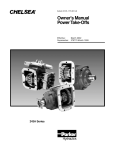
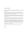
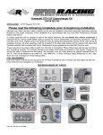
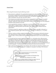
HERON ELECTRIC COMPANY LTD
Basic User and Installation Manual
Mi-4 Mi-8 Mi-12 Mi-16 Mi-144 Multi-WireController
Doc ref. Mi Multi Wire Basic November 2008
TABLE OF CONTENTS
1.
About This Controller .......................................................................................... 3
2.
Installation ........................................................................................................... 4
3.
More Inputs and Outputs..................................................................................... 6
4.
Getting to know Your Controller .......................................................................... 7
5.
Resetting the Clock, Day and Date ..................................................................... 8
6.
Set Up or Edit an Irrigation Program. .................................................................. 9
7.
Set Up or Edit an Automatic Program Start Time............................................. 10
8.
Starting and Stopping........................................................................................ 11
9.
A Couple of Short Cuts ..................................................................................... 13
10.
Faults.............................................................................................................. 15
11.
Taking Care of Your Controller ....................................................................... 16
12.
Changing Basic Controller Options................................................................. 17
2
1.
About This Controller
Congratulations, you are now the owner of a Heron Mi irrigation controller.
Your controller will operate 24volt AC solenoid valves. The controller will run the valves for the length of
time, and in the order you specify. This sequence of running solenoid valves is known as an irrigation
program.
Irrigation programs can be started automatically at pre-set start times. Alternatively, an irrigation program, a
single solenoid valve or the pump, can be started manually at any time.
* DC valves can be operated from a DC controller.
3
2.
Installation
WARNING Installation should be carried out by a Competent Electrician.
Mounting the Controller
The controller should be mounted on a wall using four screws, one screw through each corner lid bolthole.
Warning: Additional holes should not be drilled through the controller casing.
Do not mount the controller in direct sunlight. Do not mount the controller where it can be exposed to
temperatures above 40 deg C.
Wiring Up Your Controller
The Mi-4 and Mi-8 controllers should be wired up as shown in Fig 1 below.
The Mi-12, Mi-16 and Mi-144 controllers should be wired up as shown in Fig 2.
For an Mi-144 with more than 16 valves, connect the output expansion box to the expansion box
connectors. You can use either connector.
Connecting Mains Supply
IMPORTANT. Switch off the mains supply before connecting the controller.
Check that the MAINS SUPPLY VOLTAGE IS THE SAME AS THE VOLTAGE OF THE CONTROLLER.
The controller voltage is displayed on the inside the controller casing.
The mains supply should be fused with a 3-amp fuse and be connected via a Residual Current Circuit
Breaker as per any equipment used in damp conditions.
Connect the mains supply to the three terminals inside the IEC plug Live to L, Neutral to N and Earth to E as
shown in Figs 1 and 2.
Wire the controller directly back to the main distribution panel. This is particularly important when large
pumps or inductive electrical loads are also used.
Connecting Solenoid Valves
Connect each solenoid valve to the appropriate output as shown in Figs 1 and 2. The common wire from
each solenoid valve should be connected to the "C1" terminal. Valves can be connected in parallel provided
the maximum valve output current does NOT exceed the output current rating of the controller.
The solenoid output voltage is an Extra Low Safety Voltage. Keep solenoid cables and connections well
away mains voltages as per regulations for Extra Low Safety Voltages.
Connecting Pumps
Two pump control outputs are available, namely “Pump-1” and “Pump-2”.
The “Pump-1” output is across the "O1", "C1" terminals. Connect a suitable 24V relay across these
terminals to control the pump.
The second pump output is across “O3” and “C1”. Connect a suitable 24V relay across these terminals to
control the second pump. The second pump output can be attached to programs by configuring pump
control Option
Surge Earth
If your controller has a surge terminal (marked E1) connect this terminal to a local dedicated earth rod. If this
is not possible connect to a good earth.
4
Fig 1 Output Wiring for Mi-4 and Mi-8
4
8
I1 I2 I3
N
24V Solenoid
Valves
E
L
SE 1
C2
Mains
Input
Fuse
C1 terminals
are internally connected
Surge
Earth
C1
C1
F2
Permanent 24 O/P is
on O2 Fused by F2
Output Wiring
O1
O2
O3
Mains
F1
Transformer
You must
use the
cable tie
Pump 1 Pump 2 Remote Remote FlowMeter
Starter Starter Stop Start
Input
Connect to dedicated
earth rod
or to earth
Fig 2 Output Wiring for Mi-12, Mi-16 and Mi-144
E
L
N
You must
use the
cable tie
SE 1
C1 terminals
are internally connected
4
8
12
16
I1 I2 I3
C2
Mains
Input
Fuse
Surge
Earth
C1
C1
F2
Permanent 24 O/P is
on O2 Fused by F2 Expansion Box
Connectors
Output Wiring
O1
O2
O3
Mains
F1
Transformer
24V Solenoid
Valves
Pump 1 Pump 2 Remote Remote FlowMeter
Start
Starter Starter Stop
Input
Connect to dedicated
earth rod
or to earth
IMPORTANT: YOU MUST CONNECT SURGE EARTH!
5
3.
More Inputs and Outputs
Remote Start
The remote start input is across "I2" and "C2". Joining these terminals will start program 1. The terminals
have to be connected for only a short period, 1 second, to activate the program. The contact must be
broken before the program will start again.
Remote Stop/Low Water Cut Out
The remote stop input is across "I1" and "C2". Joining these inputs halts the irrigation programs. The
programs will continue once the short is removed.
This input may be connected to a float switch in the water reservoir so that the irrigation sequence is halted
if the water level is low.
When the remote Stop Input is active the following messages can be displayed depending upon Options 9
and 10.
Low Tank
“Low Tank” indicates that the water level in the storage tank is low. The irrigation program will temporarily
stop. Once the water tank has been filled, the irrigation program will start again.
Freeze
“Freeze” indicates that a sensor connected to the remote stop input has been activated. Once the freeze
condition has been removed from the input, the irrigation program will start again from the point at which it
was temporarily halted.
Stop
“Stop” indicates that a sensor connected to the remote stop input has been activated. In this case, the
irrigation program will not restart when the remote stop condition is removed.
24VAC Permanent Output
A 24VAC permanent output is available across the terminals marked O2 and C1. This output is to supply
low power 24VAC devices such as Heron interface cards and the Heron GSM module. This output is fused
with a F2 a 0.3A fuse.
6
4.
Getting to know Your Controller
When you switch on the power the Main Menu will be displayed, as shown below.
MAIN MENU
>Program Starts
Programs
Set Clock
To select any Main Menu item press the OK/SELECT button.
To return to the Main Menu at any time press the MENU button.
If you press MENU button on the Menu Page you will display the Time Page as shown below. The Time
Page shows what valves are currently running.
11:00
TUE
VALVES OFF
Pressing the MENU button from the Time Page will return you to the Main Menu.
7
5.
Resetting the Clock, Day and Date
Select “Set Clock” from the Main Menu.
The following screen will be displayed.
SET CLOCK
Time 10:50:11
Date 01/03/08
Day Fri
Use the Left and Right arrow keys to move the cursor over the current time to change the time.
Press Arrow Down to move cursor over the Date to change the date
Position the flashing cursor over the “day” field press the Select/OK button to toggle through the days of the
week until the current day is displayed.
Press the MENU button to return to the Main Menu.
8
6.
Set Up or Edit an Irrigation Program.
Select “Programs” from the Main Menu.
The following screen will be displayed.
EDIT PROGRAM
Select Prog? 1
Mins:Secs
Initially your controller will be set up to have only 1 program so Press OK on this page.
NOTE: Your controller can run up to 30 irrigation programs. The number of programs your controller can operate can be changed by
setting your controller Options. See section 13 “Changing Basic Configuration Options”.
PROGRAM 1
1 Valve 1
1 Valve 2
1 Valve 3
#01
0:00
0:00
0:00
NOTE: Valve times are displayed in minutes and seconds.
Initially the number of valves in a program will be equal to the controller size, an Mi-4 controller will have 4 valves displayed and a Mi-8
controller 8 valves You can increase or decrease the number of valves in any program by setting Program Options.
The number in the top right hand corner of the display is the “line number” for the valve so you know where you are in the programs..
Use the arrow keys to move the flashing cursor over the valve “minutes” and “seconds” fields. Use the
number keys to set the time required for each valve in the program to run.
In the example below, Valve 01 will run for 2 minutes, 30 seconds. The next valve in the program to run will
be Valve 03. Valve 03 will run for 5 minutes, 10 seconds. Note: Valve 02 will not operate when the irrigation
program runs as the time is zero.
PROGRAM 1
1 Valve 1
1 Valve 2
1 Valve 3
Press the Menu button to return to the Main Menu.
9
#01
2:30
0:00
5:10
7.
Set Up or Edit an Automatic Program Start Time
Select “Prog Starts” from the Main Menu.
The following screen will be displayed.
24HR STARTS
Prog 1 at
0:00
Prog 1 at
0:00
Prog 1 at
0:00
#01
off
off
off
NOTE: Initially your controller will be set to have a maximum of 3 automatic program starts a day (24 hours). Your controller can have
up to 60 automatic starts. The number of automatic starts can be changed by setting the controller’s Options. See section 13 “Changing
Basic Configuration Options”.
The time is displayed in hours and minutes. A start time should be entered using 24hour clock times.
Use the arrow keys to move the flashing cursor over the program number. Use the number keys to enter
the number of the program to be started.
Use the arrow keys to move the flashing cursor over the hours and minutes fields. Use the number keys to
enter the start time of the program.
An automatic start must be activated in order for it to work. Move the flashing cursor over the “OFF”
field and press the OK/Select button. (OFF will change to ON). . The automatic start has now been
activated as shown below.
24HR STARTS
Prog 3 at
6:00
Prog 3 at
12:00
Prog 7 at
21:30
#01
on
on
off
In the example above , Program 3 will start at 6:00am and then again at 21:30.
Although a start time of 21:30 has been entered for Program 7, it will NOT run. The automatic start has not
been switched on.
Press the MENU button to return to the Main Menu.
10
8.
Starting and Stopping
To manually start a program, a valve or the pump, press the START button. The following screen will be
displayed.
MANUAL
>Start
Start
Start
START
Program
Valve
Pump
Program Start
To start a program press OK
START PROG
Start Prog
1
Enter the number of the program to be started. Press OK to start the selected program.
Valve Start
To start a valve, position the flashing cursor next to the “Start Valve” option and press OK. The following
screen will be displayed.
START VALVE
Valve
001
Mins
1
Enter the number of the valve to be started and the number of minutes it is to run for. Press OK to start the
selected valve.
11
Pump Start
To start a pump, position the flashing cursor next to the “Start Pump” option and press OK button.
The following screen will be displayed.
START PUMP
Start Pump
1
Hrs 1
Enter the number of hours for the pump to run and press OK to start the selected pump.
Manual Stop
Pressing the STOP button at any time when a pump, valve or program is running will stop the pump, valve
or program immediately.
12
9.
A Couple of Short Cuts
Set All
When setting up an irrigation program, the Set All button allows a quick method of setting a number of
valves to run for the same length of time. Select “Programs” from the Main Menu.
The following screen will be displayed.
EDIT PROGRAM
Select Prog? 1
Mins:Secs
Press OK to select Program 1.
PROGRAM 1
1 Valve 01
1 Valve 02
1 Valve 03
#01
0:00
0:00
0:00
Press Set All button. The following screen will be displayed. Enter the range of valves to be set to
the same run time.
SET ALL
LINE NUM
1 to 0
Time
0:00
The valve range is specified in terms of the line number of a valve in the irrigation program. The line number
of a given valve is displayed in the top right hand corner of the program screen.
Enter the number of minutes and seconds these valves are to run for.
In the example below, valves between line number 10 and 15 have all been set to run for 3 minutes 30
seconds each.
SET ALL
LINE NUM
10 to 15
Time
3:30
Press the MENU or SETALL button to return the Edit Program screen.
13
Manual Advance
When an irrigation program is running, press Manual Advance to move the program onto the next
valve in the sequence.
This can be useful when testing your system.
14
10.
Fault Log
If a fault occurs “Fault” will appear in the Main Menu.
MAIN MENU
Program Starts
Programs
>Fault
To view the fault log select “Fault” from the Main Menu.
The following screen will be displayed. .
12:06
FAULT PAGE
VALVE 02
O/L
In the example above, there was a current overload when valve 2 was running.
15
11.
Taking Care of Your Controller
Never - use sharp objects to press the buttons on your controller. Avoid pressing the buttons with your
fingernails.
Always - ensure the lid screws are screwed down tightly to keep the inside of the controller dry and to
reduce exposure to high humidity.
16
12.
Changing Basic Controller Options
This section describes the basic configuration options you can set on your controller. There are 16 basic
options. If you need to use the more advanced features please refer to the ‘Advanced Options’ manual.
To access the controller’s basic configuration options, Press and Hold the Advance button. The following
screen will be displayed.
OPTIONS
>Standard Opt
Select “Standard Opt”. The following screen lists the controller’s basic configuration options.
OPTIONS
Number of Valves
Num 24Hr Starts
Num Weekly Starts
#01
12
03
00
Use either the number keys of press the OK/Select button to set the configuration option to its required
value.
The chart below lists the default valve and allowed values for each of the configuration options.
IMPORTANT: Always fully test any new configuration values after you have changed them to
ensure the controller functions as you require.
Note:
Your irrigation installer or dealer may have already set the configuration options to the required values for you. If you want
Options on the Main Menu set Option 15 to 1.
No.
Brief Description
Allowed
values
Set number of valves.
Set number of Daily automatic starts.
Set number of Weekly automatic starts.
The number of irrigation programs
Set pump pressurisation time in minutes.
Set pump pressurisation time in seconds.
Rain sensor connected and number of historical days
to be taken into account when measuring rainfall.
Rain on/off switch connected.
Display the global percentage adjustment of
irrigation programs page AND the display of the
enable/disable all automatic starts page.
Controller does a permanent Stop instead of Freeze
Display Low Tank instead of Freeze or Stop
4 –144
0-60
0-60
1-99
0-59
0-59
0-4
Use gallons rather than litres for flow measurements.
Enable the changing of valve order within an
irrigation program.
Turn Valve Information display on /off
Display Options on the Main Menu
Display advanced configuration options
Y/N
Y/N
Option
1
2
3
4
5
6
7
Number of Valves
Num 24hr Starts
Num Weekly Starts
Number of Prog
Pump Prime Mins
Pump Prime Secs
Rain Days
7
8
Rain Switch Connected
Water Budget
9
10
11
12
13
Input1 Stop
Input1 Low Tank
Note Used
Use Gallons
Config Programs
14
15
16
Valve Info
Options on Main Menu
Advanced Options
17
99
Y/N
Y/N
Y/N
Y/N
Y/N
0-2
1. Number of Valves
Set this to the number of valves attached to your controller.
2. Number 24hr Starts
If you need to increase or decrease the number of automatic starts allowed within a 24hour period, use this
option. Enter the required number of automatic starts. There will be no change to the operation of the
controller just more daily automatic start will be listed. If you do not want any 24hr starts set this Option to 0.
3. Number Weekly Starts
If you require weekly starts, enter the number required under this option.
When Program Starts is selected from the Main Menu, an additional screen, as shown below, will be
displayed.
This will enable you to select and set up either the 24hr or weekly starts.
PROG STARTS
24hr Starts
>Weekly Starts
If Weekly Starts .is selected then the following screen is displayed.
WEEKLY STARTS
Prog 1 Mon
0:00
Prog 1 Mon
0:00
#01
Off
Off
First enter the number of the program to be started.
To set the day of the week move the cursor under MON and press the Select/OK button until the correct
day of the week is displayed.
Move the cursor to the “time” field and set the program Start Time.
The automatic start must then be activated. Move the cursor to the “off” field”. Press the Select/OK
button to change this field to “on”.
In the example below, Program 1 will start at 10:15 am on Tuesday. Program 2 will start on Wednesday at
21:00pm.
WEEKLY STARTS
1
Prog 1 Tue
10:15 On
Prog 2 Wed
21:00 On
18
4. Number of Irrigation Programs
Set this option to the number of irrigation programs you need. The controller can support 1 to 60 irrigation
programs.
5. Pump Pressurisation Time in Minutes
The pump pressurisation time, minutes, can be set with this option. Values between 0 and 59 minutes are
allowed.
6. Pump Pressurisation Time in Seconds
The pump pressurisation time, seconds, can be set with this option. Values between 0 and 59 seconds are
allowed.
7. Rain Sensor or Rain Switch Connected
Rain Sensor
The Heron rain sensor allows the irrigation program to be reduced depending on the amount of rain that has
fallen over the last few days. Irrigation programs can be reduced by 25%, 50%, 75% or 100%.
If you have a Heron rain sensor, set this option to the number of days you wish the rain sensor to work over.
This is rolling measurement. For example if you set this option to 3 then rain that has fallen within the last 3
days will still be included in the rain fall measurement. The maximum value you can set option to is 4.
Setting this option to zero will disable the rain sensor.
Connecting the Rain Sensor
Connect the two terminals inside the rain sensor to Input 2 (across "I2" and "C2”). The terminals in the rain
sensor are accessed by removing the bottom of the rain sensor.
Using the Rain Sensor
When this option is set , “Rain Fall” will appear in the Main Menu.
MAIN MENU
Program Starts
Programs
>Rain Fall
Select “Rain Fall” from the Main Menu.
The following screen will be displayed.
RAIN FALL
Rain Fall
is
Reduction Now
Reduce by 25%
19
0mm
0%
3mm
The current rainfall measurement in millimetres, and the current level of water reduction, are displayed.
RAIN FALL
Reduce by 50%
Reduce by 75%
Reduce by 100%
6mm
9mm
12mm
In the example above, 0 mm of rainfall has been measured over the specified period. There has currently
been no reduction in irrigation.
If the measured rainfall reaches 3 mm, then irrigation programs will automatically be reduced by 25%. If 6
mm of rainfall is measured, programs will be reduced by 50% and if there is 9 mm of rainfall, irrigation
programs will be reduced by 75%. At 12 mm of rainfall irrigation programs will not run.
Testing the Rain Sensor
The rain sensor can be tested by pressing the spoon down inside the rain sensor.
Note: The rain sensor has no effect on a manual valve start.
Rain On/Off Switch
The Heron controller can also operate with a simple On/Off rain switch. If you have a simple ON/Off rain
switch set this option to “99”. The On Off rain switch is also connected across I2, C2.
8. Water Budget
The water budget option allows:
•
All irrigation run times to be temporarily adjusted by a specified percentage (0%-250%).
•
All automatic starts to be enabled or disabled.
. If the water budget option is set to “Y”, then “Water Budget” appears in the Main Menu.“
MAIN MENU
Program Starts
Program
>Water Budget
Select “Water Budget” from the Main Menu.
The following screen will be displayed.
WATER BUDGET
Global Adjust 100%
Starts Enabled Y
20
If automatic starts are to be disabled set the “Starts Enabled “ field to “N”. “Starts Disabled” will appear on
the Time Page. No irrigation programs will run.
A Global Percentage Adjust value from 1% to 250% can be entered.
IMPORTANT: Do not leave the percentage value at 0%. No irrigation will run.
9. Remote Stop Option
This controls whether irrigation programs should freeze or permanently stop when the remote stop input is
activated.
Set this option to ‘N’ to freeze irrigation programs. Irrigation programs will start again from the point at which
they stopped when the remote stop condition is removed.
Set this option to ‘Y’ to stop irrigation programs. Irrigation programs will not automatically start again when
the remote stop condition is removed.‘
10. Low Tank Display
The “Low Tank” display option changes the remote stop input message to ‘Low Tank’. To display ‘Low tank'
instead of ‘Freeze’ or ‘Stop’, set this option to Y’. Default is ‘N’.
11. Not Used
12. Use Gallons
If you wish to use Gallons rather than Litres set this option to “Y”.
13. Configure Programs
If you wish to change the order in which valves are displayed and run in an irrigation program, then this
option should be set to “Y”. Any valve can be run in any order within an irrigation program.
For example, if you want to create the following sequence for irrigation program 2.
•
•
•
Valve 7 – run for 3 minutes
Valve 5 – run for 1 minute, 30 seconds
Valve 9 – run for 2 minutes.
Select “Programs” from the Main Menu.
The following screen will be displayed.
EDIT PROGRAM
Select Prog? 1
Mins:Secs
21
Enter the number of the irrigation program you wish to configure, in this case “2”. Press OK.
Step 1 - Use the arrow keys to place the flashing cursor over the valve number on line 01. The valve name
will change from “Valve” to “Name”. Enter the number of the valve to run first in the irrigation sequence. In
this example enter the value “7”.
Step 2 - Use the arrow keys to place the flashing cursor over the valve time on line 01. The valve name will
change back to “Valve”. Enter the required run time for the first valve in the irrigation sequence. In this
example enter the value “3:00”.
Use the arrow keys to place the flashing cursor over the valve number on line 02.
Repeat steps 1 and 2 above to enter the details of the second valve to be run in the irrigation sequence. In
this case, set the valve number to “5”, and the run time to “1:30”.
Use the arrow keys to place the flashing cursor over the valve number on line 03.
Repeat steps 1 and 2 above to enter the details of the third valve to be run in the irrigation sequence. In this
case, set the valve number to “9”, and the run time to “2:00”.
PROGRAM 2
1 Valve 7
1 Valve 5
1 Valve 9
#01
3:00
1:30
2:00
Changing the Zone Number
In the example below, there are three valves displayed called VALVE 1, VALVE 2 and VALVE 3.
The number on the left is the irrigation zone number for the valve. They are all set to 1 so all valves are in
the same zone (zone1). As they are in the same zone NO valves will run together.
If, for example, you wanted VALVE 01 and VALVE 02 to run together you would need to assign them to
different irrigation zones, as follows:
To do this move the cursor over the zone number for VALVE 02 and change it to 2.
PROGRAM 2
1 Valve 1
2 Valve 2
1 Valve 3
22
#01
2:00
1:30
1:30
14. Valve Info.
Valve Information allows you to change the properties of valves. For example you can change the name of
the valve. If you wish to edit calve information set this option to Y.
When this option is set, “Valve Info” will appear in the Main Menu.
MAIN MENU
Program Starts
Programs
>Valve Info
15. Display “Options” on the Main Menu
If you require to enter Options from the Main Menu set Option 15 to “Y”.
With Option 15 set to “N”, the only way to access ‘Options’ is to press and hold the Advance button for 5
seconds.
16. Display Advanced Options
If you wish to use the ‘Advanced Options’ set Option 16 to “1”.
If you wish to use the Program Options or the Pump Configuration Options as well, set Option 16 to “2”.
23