1
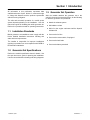
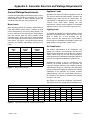
Installation
Commercial Mobile Generator Sets
Model:
7ER
TP-6034 10/02a
Table of Contents
Safety Precautions and Instructions . . . . . . . . . . . . . . . . . . . . . . . . . . . . . . . . . . . . . . . . . . . . . . . . . . . . . . . . . . . . I
Section 1. Introduction . . . . . . . . . . . . . . . . . . . . . . . . . . . . . . . . . . . . . . . . . . . . . . . . . . . . . . . . . . . . . . . . . . . . . .
1.1 Installation Standards . . . . . . . . . . . . . . . . . . . . . . . . . . . . . . . . . . . . . . . . . . . . . . . . . .
1.2 Generator Set Specifications . . . . . . . . . . . . . . . . . . . . . . . . . . . . . . . . . . . . . . . . . . . .
1.3 Generator Set Operation . . . . . . . . . . . . . . . . . . . . . . . . . . . . . . . . . . . . . . . . . . . . . . .
1
1
1
1
Section 2. Location and Mounting . . . . . . . . . . . . . . . . . . . . . . . . . . . . . . . . . . . . . . . . . . . . . . . . . . . . . . . . . .
2.1 General Considerations . . . . . . . . . . . . . . . . . . . . . . . . . . . . . . . . . . . . . . . . . . . . . . . .
2.2 Location . . . . . . . . . . . . . . . . . . . . . . . . . . . . . . . . . . . . . . . . . . . . . . . . . . . . . . . . . . . . .
2.3 Vehicle-Floor Mounting . . . . . . . . . . . . . . . . . . . . . . . . . . . . . . . . . . . . . . . . . . . . . . . . .
2.4 Extended-Shaft Mounting . . . . . . . . . . . . . . . . . . . . . . . . . . . . . . . . . . . . . . . . . . . . . . .
3
3
3
3
4
Section 3. Cooling System . . . . . . . . . . . . . . . . . . . . . . . . . . . . . . . . . . . . . . . . . . . . . . . . . . . . . . . . . . . . . . . . .
3.1 Air Requirements . . . . . . . . . . . . . . . . . . . . . . . . . . . . . . . . . . . . . . . . . . . . . . . . . . . . . .
3.2 High Water Temperature Switch . . . . . . . . . . . . . . . . . . . . . . . . . . . . . . . . . . . . . . . . .
5
5
5
Section 4. Exhaust System . . . . . . . . . . . . . . . . . . . . . . . . . . . . . . . . . . . . . . . . . . . . . . . . . . . . . . . . . . . . . . . . .
4.1 Planning . . . . . . . . . . . . . . . . . . . . . . . . . . . . . . . . . . . . . . . . . . . . . . . . . . . . . . . . . . . . .
4.2 Clearance Requirements . . . . . . . . . . . . . . . . . . . . . . . . . . . . . . . . . . . . . . . . . . . . . . .
4.3 Exhaust Piping, If Used . . . . . . . . . . . . . . . . . . . . . . . . . . . . . . . . . . . . . . . . . . . . . . . .
7
8
8
8
Section 5. Fuel System . . . . . . . . . . . . . . . . . . . . . . . . . . . . . . . . . . . . . . . . . . . . . . . . . . . . . . . . . . . . . . . . . . . .
9
5.1 Fuel Tank . . . . . . . . . . . . . . . . . . . . . . . . . . . . . . . . . . . . . . . . . . . . . . . . . . . . . . . . . . . .
9
5.2 Fuel Lines . . . . . . . . . . . . . . . . . . . . . . . . . . . . . . . . . . . . . . . . . . . . . . . . . . . . . . . . . . . . 10
5.3 Fuel Pump Lift and Fuel Consumption . . . . . . . . . . . . . . . . . . . . . . . . . . . . . . . . . . . . 10
5.4 Fuel Filters or Strainers . . . . . . . . . . . . . . . . . . . . . . . . . . . . . . . . . . . . . . . . . . . . . . . . . 10
Section 6. Electrical System . . . . . . . . . . . . . . . . . . . . . . . . . . . . . . . . . . . . . . . . . . . . . . . . . . . . . . . . . . . . . . . .
6.1 Electrical Connections . . . . . . . . . . . . . . . . . . . . . . . . . . . . . . . . . . . . . . . . . . . . . . . . .
6.2 AC Load Lead Connections . . . . . . . . . . . . . . . . . . . . . . . . . . . . . . . . . . . . . . . . . . . . .
6.3 Circuit Protection . . . . . . . . . . . . . . . . . . . . . . . . . . . . . . . . . . . . . . . . . . . . . . . . . . . . . .
6.3.1
Circuit Breaker Considerations . . . . . . . . . . . . . . . . . . . . . . . . . . . . . . . . . .
6.3.2
Circuit Breaker Installation . . . . . . . . . . . . . . . . . . . . . . . . . . . . . . . . . . . . . .
6.4 Battery and Connections . . . . . . . . . . . . . . . . . . . . . . . . . . . . . . . . . . . . . . . . . . . . . . .
6.5 Remote Switch Connection . . . . . . . . . . . . . . . . . . . . . . . . . . . . . . . . . . . . . . . . . . . . .
11
11
11
13
13
14
15
16
Section 7. Installation Drawing . . . . . . . . . . . . . . . . . . . . . . . . . . . . . . . . . . . . . . . . . . . . . . . . . . . . . . . . . . . . . 17
Section 8. Reconnection/Adjustments . . . . . . . . . . . . . . . . . . . . . . . . . . . . . . . . . . . . . . . . . . . . . . . . . . . . . . 19
8.1 Four-Lead Reconnection . . . . . . . . . . . . . . . . . . . . . . . . . . . . . . . . . . . . . . . . . . . . . . . 19
8.2 Voltage Regulation Adjustment . . . . . . . . . . . . . . . . . . . . . . . . . . . . . . . . . . . . . . . . . . 21
Appendix A. Generator Selection and Wattage Requirements . . . . . . . . . . . . . . . . . . . . . . . . . . . . . . . . . A-1
Appendix B. Glossary of Abbreviations . . . . . . . . . . . . . . . . . . . . . . . . . . . . . . . . . . . . . . . . . . . . . . . . . . . . . A-2
TP-6034 10/02
Table of Contents
Notes
Table of Contents
TP-6034 10/02
Safety Precautions and Instructions
IMPORTANT
SAFETY
INSTRUCTIONS. Electromechanical
equipment, including generator sets,
transfer switches, switchgear, and
accessories, can cause bodily harm
and pose life-threatening danger when
improperly installed, operated, or
maintained. To prevent accidents be
aware of potential dangers and act
safely. Read and follow all safety
precautions and instructions. SAVE
THESE INSTRUCTIONS.
This manual has several types of safety
precautions and instructions: Danger,
Warning, Caution, and Notice.
DANGER
Danger indicates the presence of a
hazard that will cause severe
personal injury, death, or substantial
property damage.
WARNING
Warning indicates the presence of a
hazard that can cause severe
personal injury, death, or substantial
property damage.
Accidental Starting
WARNING
Accidental starting.
Can cause severe injury or death.
Disconnect the battery cables before
working on the generator set.
Remove the negative (--) lead first
when disconnecting the battery.
Reconnect the negative (--) lead last
when reconnecting the battery.
Disabling
the
generator set.
Accidental starting can cause
severe injury or death.
Before
working on the generator set or
equipment connected to the set,
disable the generator set as follows:
(1) Place the generator set start/stop
switch in the STOP position.
(2) Disconnect the power to the battery
charger, if equipped. (3) Remove the
battery cables, negative (--) lead first.
Reconnect the negative (--) lead last
when reconnecting the battery. Follow
these precautions to prevent the
starting of the generator set by the
remote start/stop switch.
CAUTION
Caution indicates the presence of a
hazard that will or can cause minor
personal injury or property damage.
Battery
WARNING
NOTICE
Notice communicates installation,
operation, or maintenance information
that is safety related but not hazard
related.
Safety decals affixed to the equipment
in prominent places alert the operator
or service technician to potential
hazards and explain how to act safely.
The decals are shown throughout this
publication to improve operator
recognition.
Replace missing or
damaged decals.
TP-6034 10/02
Sulfuric acid in batteries.
Can cause severe injury or death.
Wear protective goggles and
clothing. Battery acid may cause
blindness and burn skin.
Battery electrolyte is a diluted
sulfuric acid. Battery acid can cause
severe injury or death. Battery acid
can cause blindness and burn skin.
Always wear splashproof safety
goggles, rubber gloves, and boots
when servicing the battery. Do not
open a sealed battery or mutilate the
battery case. If battery acid splashes in
the eyes or on the skin, immediately
flush the affected area for 15 minutes
with large quantities of clean water.
Seek immediate medical aid in the case
of eye contact. Never add acid to a
battery after placing the battery in
service, as this may result in hazardous
spattering of battery acid.
Battery acid cleanup. Battery acid
can cause severe injury or death.
Battery acid is electrically conductive
and corrosive. Add 500 g (1 lb.) of
bicarbonate of soda (baking soda) to a
container with 4 L (1 gal.) of water and
mix the neutralizing solution. Pour the
neutralizing solution on the spilled
battery acid and continue to add the
neutralizing solution to the spilled
battery acid until all evidence of a
chemical reaction (foaming) has
ceased. Flush the resulting liquid with
water and dry the area.
Battery gases. Explosion can cause
severe injury or death. Battery gases
can cause an explosion. Do not smoke
or permit flames or sparks to occur near
a battery at any time, particularly when
it is charging. Do not dispose of a
battery in a fire. To prevent burns and
sparks that could cause an explosion,
avoid touching the battery terminals
with tools or other metal objects.
Remove all jewelry before servicing the
equipment. Discharge static electricity
from your body before touching
batteries by first touching a grounded
metal surface away from the battery. To
avoid sparks, do not disturb the battery
charger connections while the battery
is charging. Always turn the battery
charger off before disconnecting the
battery connections. Ventilate the
compartments containing batteries to
prevent accumulation of explosive
gases.
Safety Precautions and Instructions I
Battery short circuits. Explosion
can cause severe injury or death.
Short circuits can cause bodily injury
and/or
equipment
damage.
Disconnect
the
battery
before
generator
set
installation
or
maintenance. Remove all jewelry
before servicing the equipment. Use
tools with insulated handles. Remove
the negative (--) lead first when
disconnecting the battery. Reconnect
the negative (--) lead last when
reconnecting the battery.
Never
connect the negative (--) battery cable
to the positive (+) connection terminal
of the starter solenoid. Do not test the
battery condition by shorting the
terminals together.
Combustible materials. A fire can
cause severe injury or death.
Generator set engine fuels and fuel
vapors are flammable and explosive.
Handle these materials carefully to
minimize the risk of fire or explosion.
Equip the compartment or nearby area
with a fully charged fire extinguisher.
Select a fire extinguisher rated ABC or
BC for electrical fires or as
recommended by the local fire code or
an authorized agency.
Train all
personnel
on
fire extinguisher
operation
and
fire
prevention
procedures.
Exhaust System
WARNING
Engine Backfire/Flash
Fire
WARNING
Fire.
Can cause severe injury or death.
Do not smoke or permit flames or
sparks near fuels or the fuel system.
Servicing the fuel system. A flash
fire can cause severe injury or death.
Do not smoke or permit flames or
sparks near the carburetor, fuel line,
fuel filter, fuel pump, or other potential
sources of spilled fuels or fuel vapors.
Catch fuels in an approved container
when removing the fuel line or
carburetor.
Servicing the air cleaner. A sudden
backfire can cause severe injury or
death. Do not operate the generator
set with the air cleaner removed.
II Safety Precautions and Instructions
Carbon monoxide.
Can cause severe
fainting, or death.
nausea,
The exhaust system must be
leakproof and routinely inspected.
Generator set operation. Carbon
monoxide can cause severe nausea,
fainting, or death. Carbon monoxide
is an odorless, colorless, tasteless,
nonirritating gas that can cause death if
inhaled for even a short time. Avoid
breathing exhaust fumes when working
on or near the generator set. Never
operate the generator set inside a
building unless the exhaust gas is
piped safely outside. Never operate
the generator set where exhaust gas
could accumulate and seep back inside
a potentially occupied building or
vehicle. Do not obstruct the exhaust
outlet when parking your vehicle. The
exhaust gases must discharge freely to
prevent carbon monoxide from
deflecting into the vehicle.
Carbon
monoxide
symptoms.
Carbon monoxide can cause severe
nausea, fainting, or death. Carbon
monoxide is a poisonous gas present in
exhaust gases. Carbon monoxide
poisoning symptoms include but are
not limited to the following:
D Light-headedness, dizziness
D Physical fatigue, weakness in
joints and muscles
D Sleepiness, mental fatigue,
inability to concentrate
or speak clearly, blurred vision
D Stomachache, vomiting, nausea
If experiencing any of these symptoms
and carbon monoxide poisoning is
possible, seek fresh air immediately
and remain active. Do not sit, lie down,
or fall asleep. Alert others to the
possibility of carbon monoxide
poisoning. Seek medical attention if
the condition of affected persons does
not improve within minutes of breathing
fresh air.
Installing the exhaust tail pipe.
Carbon monoxide can cause severe
nausea, fainting, or death. Install the
exhaust system tail pipe to prevent the
drawing of discharged exhaust gases
into the vehicle interior through
windows, doors, air conditioners, and
other openings. Do not use flexible tail
piping because it could crack and allow
lethal exhaust fumes to enter the
vehicle.
Inspecting the exhaust system.
Carbon monoxide can cause severe
nausea, fainting, or death. For the
safety of the vehicle’s occupants, install
a carbon monoxide detector. Consult
the coach builder or dealer for
approved detector location and
installation. Inspect the detector before
each generator set use. In addition to
routine exhaust system inspection, test
the carbon monoxide detector per the
manufacturer’s instructions and keep
the detector operational at all times.
TP-6034 10/02
Fuel System
WARNING
Hazardous Noise
CAUTION
Explosive fuel vapors.
Can cause severe injury or death.
Hazardous noise.
Can cause hearing loss.
Use extreme care when handling,
storing, and using fuels.
Never operate the generator set
without a muffler or with a faulty
exhaust system.
The fuel system. Explosive fuel
vapors can cause severe injury or
death. Vaporized fuels are highly
explosive. Use extreme care when
handling and storing fuels. Store fuels
in a well-ventilated area away from
spark-producing equipment and out of
the reach of children. Never add fuel to
the tank while the engine is running
because spilled fuel may ignite on
contact with hot parts or from sparks.
Do not smoke or permit flames or
sparks to occur near sources of spilled
fuel or fuel vapors. Keep the fuel lines
and connections tight and in good
condition. Do not replace flexible fuel
lines with rigid lines. Use flexible
sections to avoid fuel line breakage
caused by vibration. Do not operate the
generator set in the presence of fuel
leaks, fuel accumulation, or sparks.
Repair fuel systems before resuming
generator set operation.
Explosive fuel vapors can cause
severe injury or death.
Take
additional precautions when using the
following fuels:
Gasoline—Store gasoline only in
approved red containers clearly
marked GASOLINE.
Draining the fuel system. Explosive
fuel vapors can cause severe injury
or death. Spilled fuel can cause an
explosion. Use a container to catch fuel
when draining the fuel system. Wipe up
spilled fuel after draining the system.
Engine noise. Hazardous noise can
cause hearing loss. Generator sets
not equipped with sound enclosures
can produce noise levels greater than
105 dBA. Prolonged exposure to noise
levels greater than 85 dBA can cause
permanent hearing loss. Wear hearing
protection when near an operating
generator set.
Hazardous Voltage/
Electrical Shock
WARNING
Hazardous voltage. Moving rotor.
Can cause severe injury or death.
Operate the generator set only when
all guards and electrical enclosures
are in place.
WARNING
Hazardous voltage.
Backfeed to the utility system can
cause severe injury, death, or
property damage.
Grounding electrical equipment.
Hazardous voltage can cause
severe injury or death. Electrocution
is possible whenever electricity is
present.
Open the main circuit
breakers of all power sources before
servicing the equipment. Configure the
installation to electrically ground the
generator set, transfer switch, and
related equipment and electrical
circuits to comply with applicable codes
and standards.
Never contact
electrical leads or appliances when
standing in water or on wet ground
because these conditions increase the
risk of electrocution.
Short
circuits.
Hazardous
voltage/current can cause severe
injury or death. Short circuits can
cause bodily injury and/or equipment
damage. Do not contact electrical
connections with tools or jewelry while
making adjustments or repairs.
Remove all jewelry before servicing the
equipment.
Testing the voltage regulator.
Hazardous voltage can cause
severe injury or death. High voltage
is present at the voltage regulator heat
sink. To prevent electrical shock do not
touch the voltage regulator heat sink
when testing the voltage regulator.
(PowerBoostt, PowerBoostt III, and
PowerBoostt V voltage regulator
models only)
Electrical backfeed to the utility.
Hazardous backfeed voltage can
cause severe injury or death.
Connect the generator set to the
building/campground electrical system
only through an approved device and
after the building/campground main
switch is opened.
Backfeed
connections can cause severe injury or
death to utility personnel working on
power lines and/or personnel near the
work area. Some states and localities
prohibit unauthorized connection to the
utility electrical system.
Install a
transfer
switch
to
prevent
interconnection of the generator set
power and other sources of power.
Connect the generator set to the
building’s electrical system only
through an approved device and after
the building’s main switch is opened.
TP-6034 10/02
Safety Precautions and Instructions III
Testing live electrical circuits.
Hazardous voltage or current can
cause severe injury or death. Have
trained and qualified personnel take
diagnostic measurements of live
circuits. Use adequately rated test
equipment with electrically insulated
probes and follow the instructions of the
test equipment manufacturer when
performing voltage tests. Observe the
following precautions when performing
voltage tests: (1) Remove all jewelry.
(2) Stand on a dry, approved electrically
insulated mat. (3) Do not touch the
enclosure or components inside the
enclosure. (4) Be prepared for the
system to operate automatically.
(600 volts and under)
Hot Parts
WARNING
Servicing the exhaust system. Hot
parts can cause severe injury or
death. Do not touch hot engine parts.
The engine and exhaust system
components become extremely hot
during operation.
Combustible materials. Fire can
cause severe injury or death. A hot
exhaust system can ignite adjacent
combustible materials. Do not locate
electrical wiring, fuel lines, or
combustible materials above the
exhaust muffler. Exercise caution
when parking your vehicle to prevent
the exhaust system and hot exhaust
gases from starting grass fires.
Combustible materials. Fire can
cause severe injury or death. A hot
generator set can ignite debris in the
compartment. Keep the compartment
and generator set clean and free of
debris and combustible materials to
minimize the possibility of fire. Do not
block the fuel/oil drain opening in the
generator set mounting tray. Cut a
corresponding hole in the subfloor, if
used, for the drain opening.
Hot coolant and steam.
Can cause severe injury or death.
Before removing the pressure cap,
stop the generator set and allow it to
cool. Then loosen the pressure cap
to relieve pressure.
Moving Parts
WARNING
WARNING
Hazardous voltage. Moving rotor.
Can cause severe injury or death.
Hot engine and exhaust system.
Can cause severe injury or death.
Do not work on the generator set until
it cools.
Checking the coolant level. Hot
coolant can cause severe injury or
death. Allow the engine to cool.
Release pressure from the cooling
system before removing the pressure
cap. To release pressure, cover the
pressure cap with a thick cloth and then
slowly turn the cap counterclockwise to
the first stop. Remove the cap after
pressure has been completely
released and the engine has cooled.
Check the coolant level at the tank if the
generator set has a coolant recovery
tank.
IV Safety Precautions and Instructions
WARNING
Airborne particles.
Can cause severe
blindness.
injury
or
Wear protective goggles and clothing
when using power tools, hand tools,
or compressed air.
Tightening the hardware. Flying
projectiles can cause severe injury
or death. Loose hardware can cause
the hardware or pulley to release from
the generator set engine and can cause
personal injury.
Retorque all
crankshaft and rotor hardware after
servicing. Do not loosen the crankshaft
hardware or rotor thrubolt when making
adjustments or servicing the generator
set. Rotate the crankshaft manually in
a clockwise direction only. Turning the
crankshaft bolt or rotor thrubolt
counterclockwise can loosen the
hardware.
Servicing the generator set when it
is operating. Exposed moving parts
can cause severe injury or death.
Keep hands, feet, hair, clothing, and
test leads away from the belts and
pulleys when the generator set is
running. Replace guards, screens, and
covers before operating the generator
set.
Operate the generator set only when
all guards and electrical enclosures
are in place.
WARNING
Rotating parts.
Can cause severe injury or death.
Operate the generator set only when
all guards, screens, and covers are in
place.
TP-6034 10/02
Notice
NOTICE
This generator set has been
rewired from its nameplate voltage
to
246242
NOTICE
Voltage reconnection. Affix a notice
to the generator set after reconnecting
the set to a voltage different from the
voltage on the nameplate. Order
voltage reconnection decal 246242
from
an
authorized
service
distributor/dealer.
TP-6034 10/02
NOTICE
NOTICE
Hardware damage. The engine and
generator set may use both American
Standard and metric hardware. Use
the correct size tools to prevent
rounding of the bolt heads and nuts.
Canadian installations only. For
standby service connect the output of
the generator set to a suitably rated
transfer switch in accordance with
Canadian Electrical Code, Part 1.
NOTICE
NOTICE
When replacing hardware, do not
substitute with inferior grade
hardware.
Screws and nuts are
available in different hardness ratings.
To indicate hardness, American
Standard hardware uses a series of
markings, and metric hardware uses a
numeric system. Check the markings
on the bolt heads and nuts for
identification.
This generator set does not comply
with United States Coast Guard
(USCG) requirements and must not
be used for marine applications. For
marine installations use only generator
sets specified for marine use. USCG
Regulation 33CFR183 requires that a
generator set must be ignition
protected
when
used
in
a
gasoline-fueled environment.
Safety Precautions and Instructions V
Notes
VI Safety Precautions and Instructions
TP-6034 10/02
Section 1 Introduction
All information in this publication represents data
available at the time of print. Kohler Co. reserves the right
to change this literature and the products represented
without incurring obligation.
The safe and successful operation of a mobile power
system depends primarily on the installation. Use this
manual as a guide for installing the mobile generator set.
Refer to the operation manual for operating instructions.
1.3 Generator Set Operation
After the installer attaches the generator set to the
vehicle’s frame and connects the hoses, do the following
to make the generator set operational:
D Attach the exhaust system
D Add radiator coolant
D Add oil to the engine crankcase until the dipstick
1.1 Installation Standards
Mobile generator set installations must comply with the
Kohler detailed installation instructions following and
state and local requirements.
The installer is responsible for improper installations
resulting in penalties from noncompliance with CARB or
EPA emission standards.
indicates full
D Connect the fuel line
D Connect the remote switch, if equipped
D Connect the load leads
D Connect the battery terminals
1.2 Generator Set Specifications
Refer to the model’s specification sheet for details. Use
the spec sheet as a guide for planning the installation.
Use the current dimension drawing and wiring diagrams.
TP-6034 10/02
Introduction 1
Notes
2
Introduction
TP-6034 10/02
Section 2 Location and Mounting
2.1 General Considerations
2.3 Vehicle-Floor Mounting
Consider the following items concerning the generator
set and Section 2.2 for the proposed location.
Install the Kohler 7ER mobile generator set on an open
vehicle’s floor or truck bed. Follow the guidelines below.
Contact an authorized Kohler service distributor/dealer
with your specific application questions.
1. Select a generator set having adequate capacity to
handle the electrical load.
2. Design the fuel system to prevent fuel starvation of
the main or generator set engine.
3. Ensure that the exhaust system meets all safety
requirements after installation.
4. Ensure compatibility of all electrical systems
(battery, load, and remote switch) with the vehicle’s
electrical systems.
2.2 Location
Note: This generator set is not designed for installation
in a compartment or enclosure.
Before making final plans for locating the generator set,
ensure the following:
1. The location has sufficient room to maintain
required minimum clearances.
Minimum clearance. Allow clearance for vibration and
cooling during operation. Minimum clearance for
vibration (top, front, rear, and sides) is 38 mm (1 1/2 in.).
Keep the radiator end unobstructed for proper air flow.
Additional clearance. Generator set service requires
more clearance than 38 mm (1 1/2 in.). Design the
mounting location to allow for sufficient room to easily
remove the generator set to perform major service.
Mounting tray. Ensure that the structural members for
mounting can support the generator set’s weight and
withstand vibration.
The generator set includes
vibration mounts and a mounting tray; if desired, install
additional vibration isolating pads underneath the
generator set’s base. Use the four mounting holes in the
mounting tray to mount the generator set securely to the
vehicle to avoid unwanted movement from vibration and
road shock.
2. The location provides enough air flow to allow
required cooling and combustion.
3. The location can support the generator set weight.
4. The location provides ample room for routine
service of the generator set’s engine, controller,
cooling system, and fuel system components.
See the current generator set specification sheet or
Section 7 of this manual for generator set dimensions
and weights.
For angular operating limits, consult the operation
manual.
TP-6034 10/02
Location and Mounting 3
2.4 Extended-Shaft Mounting
If the mobile generator set includes an extended shaft,
allow adequate space at the generator end of the set for
an adapter, flexible coupling, and the operating
equipment.
The mounting flange conforms to
SAE J609a, Flange B. See Figure 2-1 for dimensions.
Note: Customers must provide the adapter and flexible
coupling for the extended-shaft option.
1-921
Figure 2-2
Hydraulic Pump
Note: Adding a hydraulic-pump drive lowers the engine
horsepower available to drive the generator.
Therefore, the engine can be overloaded. Be
aware of reduced generator output when
powering external equipment.
ADV-6450-E
Figure 2-1
Extended Shaft Dimensions
Figure 2-2 shows a Kohler mobile generator set
mounted to a hydraulic pump. The generator set
equipped with the extended-shaft option can power
external equipment to the limit of the engine’s capacity.
Note: The output shaft can pull max. horsepower. The
extended shaft is designed for powering a
direct-driven hydraulic pump.
4 Location and Mounting
TP-6034 10/02
Section 3 Cooling System
3.1 Air Requirements
Air flow around the generator set is necessary for
adequate cooling. See the current generator set
specification sheet for air requirements. The air intake
silencer/cleaner provides combustion air to the engine.
See Figure 3-1 for allowable intake restriction. The
engine/generator performance will be adversely
affected if these guidelines are neglected. Follow these
guidelines to optimize generator set performance.
Model
7ER
Figure 3-1
3.2 High Water Temperature
Switch
Each generator set includes a high water temperature
shutdown switch that automatically shuts down the set if
operating temperatures climb too high. Follow the
guidelines described in Section 3.1 to prevent
shutdowns.
Normal Intake Restriction
0.03 psi (0.79 in. H2O)
Intake Restriction
TP-6034 10/02
Cooling System 5
Notes
6 Cooling System
TP-6034 10/02
Section 4 Exhaust System
WARNING
Carbon monoxide.
Can cause severe nausea, fainting,
or death.
The exhaust system must be
leakproof and routinely inspected.
Generator set operation. Carbon monoxide can cause
severe nausea, fainting, or death. Carbon monoxide is an
odorless, colorless, tasteless, nonirritating gas that can cause
death if inhaled for even a short time. Avoid breathing exhaust
fumes when working on or near the generator set. Never
operate the generator set inside a building unless the exhaust
gas is piped safely outside. Never operate the generator set
where exhaust gas could accumulate and seep back inside a
potentially occupied building or vehicle. Do not obstruct the
exhaust outlet when parking your vehicle. The exhaust gases
must discharge freely to prevent carbon monoxide from
deflecting into the vehicle.
Carbon monoxide symptoms. Carbon monoxide can
cause severe nausea, fainting, or death. Carbon monoxide
is a poisonous gas present in exhaust gases. Carbon
monoxide poisoning symptoms include but are not limited to
the following:
D Light-headedness, dizziness
D Physical fatigue, weakness in
joints and muscles
D Sleepiness, mental fatigue,
inability to concentrate
or speak clearly, blurred vision
D Stomachache, vomiting, nausea
If experiencing any of these symptoms and carbon monoxide
poisoning is possible, seek fresh air immediately and remain
active. Do not sit, lie down, or fall asleep. Alert others to the
possibility of carbon monoxide poisoning. Seek medical
attention if the condition of affected persons does not improve
within minutes of breathing fresh air.
TP-6034 10/02
Installing the exhaust tail pipe. Carbon monoxide can
cause severe nausea, fainting, or death. Install the exhaust
system tail pipe to prevent the drawing of discharged exhaust
gases into the vehicle interior through windows, doors, air
conditioners, and other openings. Do not use flexible tail
piping because it could crack and allow lethal exhaust fumes to
enter the vehicle.
Inspecting the exhaust system. Carbon monoxide can
cause severe nausea, fainting, or death. For the safety of
the vehicle’s occupants, install a carbon monoxide detector.
Consult the coach builder or dealer for approved detector
location and installation. Inspect the detector before each
generator set use. In addition to routine exhaust system
inspection, test the carbon monoxide detector per the
manufacturer’s instructions and keep the detector operational
at all times.
WARNING
Hot engine and exhaust system.
Can cause severe injury or death.
Do not work on the generator set until
it cools.
Combustible materials. Fire can cause severe injury or
death. A hot exhaust system can ignite adjacent combustible
materials. Do not locate electrical wiring, fuel lines, or
combustible materials above the exhaust muffler. Exercise
caution when parking your vehicle to prevent the exhaust
system and hot exhaust gases from starting grass fires.
Exhaust System 7
7
4.1 Planning
4.3 Exhaust Piping, If Used
Carefully plan the generator exhaust system to ensure a
safe, quiet installation. Verify that the installation
complies with all state and local requirements and
applicable articles of the codes listed at the beginning of
this manual.
Route the exhaust piping to maintain minimum
clearances and to minimize exhaust piping bends. Use
a tail pipe as short as possible with as few bends as
possible to reduce back pressure. Design the exhaust
piping to prevent excessive back pressure of the
unit-mounted muffler. See Figure 4-1 for the allowable
exhaust back pressure. Do not apply weight or pressure
to the unit-mounted muffler, otherwise premature
exhaust-system damage will occur.
Adding
exhaust-pipe extensions to the unit-mounted muffler
may cause excessive vibration and noise transmitted to
the vehicle.
4.2 Clearance Requirements
Kohler Co. recommends a clearance of 38 mm
(1 1/2 in.) between the exhaust system parts and the
fuel system, the electrical system, and all combustible
components to protect the generator set components
and to avoid igniting adjacent combustible materials.
Model
Allowable Exhaust
Back Pressure
7ER
< 1.42 psi (1000 mm H2O)
Figure 4-1 Allowable Exhaust Back Pressure
8 Exhaust System
TP-6034 10/02
Section 5 Fuel System
WARNING
Explosive fuel vapors.
Can cause severe injury or death.
Use extreme care when handling,
storing, and using fuels.
The fuel system. Explosive fuel vapors can cause severe
injury or death. Vaporized fuels are highly explosive. Use
extreme care when handling and storing fuels. Store fuels in a
well-ventilated area away from spark-producing equipment
and out of the reach of children. Never add fuel to the tank
while the engine is running because spilled fuel may ignite on
contact with hot parts or from sparks. Do not smoke or permit
flames or sparks to occur near sources of spilled fuel or fuel
vapors. Keep the fuel lines and connections tight and in good
condition. Do not replace flexible fuel lines with rigid lines. Use
flexible sections to avoid fuel line breakage caused by
vibration. Do not operate the generator set in the presence of
fuel leaks, fuel accumulation, or sparks. Repair fuel systems
before resuming generator set operation.
5.1 Fuel Tank
Fuel system design. Design the generator set
gasoline fuel system to operate independently of the
vehicle engine fuel system if the operator may operate
both engines simultaneously. Kohler Co. recommends
using separate fuel tanks, if possible; using separate
fuel tanks is usually impractical because of space
restrictions. In most installations, both engines operate
off a common tank with a separate dip-tube
arrangement as shown in Figure 5-1. The dip-tube
arrangement prevents the larger engine from starving
the smaller engine of fuel. The generator set dip tube is
generally shorter than the vehicle dip tube to stop the
generator set before the vehicle engine runs out of fuel.
With the dip-tube arrangement, the generator may not
get fuel during a low fuel-supply situation.
Tee arrangement. Do not use the tee arrangement. Do
not tee into the fuel-supply or -return line of fuel-injected
systems.
1
2
Draining the fuel system. Explosive fuel vapors can
cause severe injury or death. Spilled fuel can cause an
explosion. Use a container to catch fuel when draining the fuel
system. Wipe up spilled fuel after draining the system.
5605613
1. Fuel line to the generator set
2. Fuel line to the vehicle engine
Figure 5-1
Two Dip Tubes in Fuel Tank
Note: Supply the fuel using a two dip-tube arrangement
if the generator shares the vehicle engine fuel
tank. Consult an authorized Kohler service
distributor/dealer for further fuel system
installation information.
TP-6034 10/02
Fuel System 9
5.2 Fuel Lines
Note: Keep fuel lines away from the exhaust system.
Routing fuel lines. Take care when routing the fuel line
from the fuel tank to the generator set. Keep the fuel
lines as short as possible but maintain adequate
clearance from the exhaust system. Route the fuel lines
along the frame or undercarriage—never route the fuel
lines inside the habitable area of the vehicle. Locate the
fuel lines with the entry point near the fuel pump. See
Section 5.3 for the fuel pump lift.
Sizing fuel lines. Size the fuel line to handle the flow of
fuel and to withstand road shock and year-round climate
conditions. Use steel tubing as the codes require. Use a
6 mm (1/4 in.) ID tubing with an 230 mm (8 in.)
(minimum) flexible section to allow free movement of the
generator set.
Fuel line size:
Fuel inlet
6 mm (1/4 in.) ID
Flexible hose sections. If a metal fuel line draws fuel
from the fuel tank, install a flexible hose section to
connect the metal line to the fuel pump. The flexible
section allows generator set vibrational motion during
operation.
See Section 7 for the fuel inlet-line
connection point.
5.3 Fuel Pump Lift and Fuel
Consumption
See Figure 5-2 for the fuel pump lift capability. Consult
the current generator set specification sheet for the
generator set fuel consumption rates. Do not exceed
3 1/2 psi fuel pump pressure to the carburetor.
Note: Fuel system alterations may adversely affect
emissions levels.
Fines resulting from
higher-than-allowable emissions levels are the
responsibility of the user.
Figure 5-2
Model
Fuel Pump Lift
m (ft.)
7ER
0.9 (3)
Fuel Pump Lift Capability (Max.)
5.4 Fuel Filters or Strainers
These generator sets are shipped with a fuel filter. No
additional fuel filter or strainer is required.
Note: Gasoline-fueled engines require a type A1 hose.
1
ADV-6450-E
1. Fuel filter
Figure 5-3
10 Fuel System
Fuel Filter Location
TP-6034 10/02
Section 6 Electrical System
WARNING
Hazardous voltage. Moving rotor.
Can cause severe injury or death.
Operate the generator set only when
all guards and electrical enclosures
are in place.
Electrical backfeed to the utility. Hazardous backfeed
voltage can cause severe injury or death. Connect the
generator set to the building/campground electrical system
only through an approved device and after the
building/campground main switch is opened. Backfeed
connections can cause severe injury or death to utility
personnel working on power lines and/or personnel near the
work area. Some states and localities prohibit unauthorized
connection to the utility electrical system. Install a transfer
switch to prevent interconnection of the generator set power
and other sources of power.
6.1 Electrical Connections
Have qualified electricians make connections.
Connections to the load leads, battery, and remote
switch panel complete the installation. To prevent
unintentional starting, make final connections to the
battery only after making all other connections.
6.2 AC Load Lead Connections
Routing. Each generator set has four color-coded load
leads. The black leads (L1 and L2) are hot, the white
lead (L0) is neutral, and the green lead is the hazard
ground. See Section 8 for the AC load lead connections.
Route the load leads directly from the junction box to the
vehicle AC circuit or transfer switch connection. Route
the load leads of all installations through flexible conduit
from the generator end bracket to the junction box.
Keep the load lead junction box accessible for service
and inspection.
Note: Keep the load lead circuit away from the
generator fuel and exhaust system components.
Note: Use field-supplied wiring capable of withstanding
temperatures of 75_C (167_F).
Connect the neutral of the AC circuit in the vehicle to the
lead L0 (white or gray). If the vehicle uses equipment
ground-type plugs and receptacles (3-pronged),
connect the green wire to the U-shaped pin. On vehicles
that also have provisions for using an outside AC power
source, completely isolate the neutral as well as the hot
(black) leads from the generator set when switching
power to the outside source. See Figure 6-1.
The following paragraphs provide details on each
connection. Refer also to the wiring diagram in the
operation manual.
Securely support or harness all wiring to the generator
set to prevent abrasion. Provide additional support for
the wiring to prevent exposure to the exhaust system
and drippage of fuel, oil, or grease. Allow at least a
51 mm (2 in.) clearance between the electrical wiring
and hot exhaust parts. Do not locate the wiring directly
below or near the fuel system parts or the oil-fill tube.
The following paragraphs cover some other points to
consider when making AC load connections.
Note: At the time of installation, make the wiring
connections accessible for inspection and
service.
TP-6034 10/02
Electrical System 11
Note: Transfer switch. Use a triple-pole, double-throw
transfer switch rated for the calculated load of the
vehicle to transfer the load from one source to the
other. Install a ground-fault circuit interrupter in
the wiring system to protect all branch circuits.
Note: For standby service connect output of the
generator to a suitably rated transfer switch in
accordance with the Canadian Electrical Code,
Part 1.
Note: AC load circuit protection. Protect the AC load
circuit of the generator set against overloading or
short circuiting with a circuit breaker(s).
AC Vehicle Circuit
AC Vehicle Circuit
Ground Fault
Circuit Protection
Ground Fault
Circuit Protection
L0
N
N
L0
N
120-V
Outside
Power
N
L1
Gen.
Set
N
N
240-V
Outside
Power
L1
L2
120 Volt
Figure 6-1
Gen.
Set
L2
120/240 Volt
Transfer Switch Connections, 3-Wire AC Circuit
12 Electrical System
TP-6034 10/02
6.3 Circuit Protection
The AC circuit breakers protect the generator set from
extreme overload. AC circuit breakers trip when they
detect a fault in the output circuit.
For application and selection information contact an
authorized distributor/dealer.
After correcting the fault, reset the AC circuit breaker(s)
by placing them in the ON position. Restart the unit. See
an authorized service distributor/dealer for AC circuit
breaker ratings. The unit’s voltage configuration
determines the circuit breaker selection.
Note: Circuit breaker ampere rating and availability are
subject to change.
6.3.1
Circuit Breaker Considerations
Mounting location. Mount the circuit breakers in the
generator set controller.
Sizing. Use the generator set voltage/frequency
configuration to determine the circuit breaker
amperage. If the circuit breaker was sized for one
voltage configuration and later the generator set is
reconnected to a different voltage, change the circuit
breaker accordingly to provide optimum protection.
Have a qualified electrician or technician install circuit
breakers and reconnect the generator set. Comply with
all governing standards and codes.
WARNING
Accidental starting.
Can cause severe injury or death.
Disconnect the battery cables before
working on the generator set.
Remove the negative (--) lead first
when disconnecting the battery.
Reconnect the negative (--) lead last
when reconnecting the battery.
TP-6034 10/02
Disabling the generator set. Accidental starting can
cause severe injury or death. Before working on the
generator set or equipment connected to the set, disable the
generator set as follows: (1) Place the generator set start/stop
switch in the STOP position. (2) Disconnect the power to the
battery charger, if equipped. (3) Remove the battery cables,
negative (--) lead first. Reconnect the negative (--) lead last
when reconnecting the battery. Follow these precautions to
prevent the starting of the generator set by the remote
start/stop switch.
WARNING
Hazardous voltage. Moving rotor.
Can cause severe injury or death.
Operate the generator set only when
all guards and electrical enclosures
are in place.
Grounding electrical equipment. Hazardous voltage can
cause severe injury or death. Electrocution is possible
whenever electricity is present. Open the main circuit
breakers of all power sources before servicing the equipment.
Configure the installation to electrically ground the generator
set, transfer switch, and related equipment and electrical
circuits to comply with applicable codes and standards. Never
contact electrical leads or appliances when standing in water
or on wet ground because these conditions increase the risk of
electrocution.
Short circuits. Hazardous voltage/current can cause
severe injury or death. Short circuits can cause bodily injury
and/or equipment damage.
Do not contact electrical
connections with tools or jewelry while making adjustments or
repairs. Remove all jewelry before servicing the equipment.
Electrical backfeed to the utility. Hazardous backfeed
voltage can cause severe injury or death. Connect the
generator set to the building/campground electrical system
only through an approved device and after the
building/campground main switch is opened. Backfeed
connections can cause severe injury or death to utility
personnel working on power lines and/or personnel near the
work area. Some states and localities prohibit unauthorized
connection to the utility electrical system. Install a transfer
switch to prevent interconnection of the generator set power
and other sources of power.
Electrical System 13
6.3.2
Circuit Breaker Installation
(Only Required for Changing
from Factory-Installed and -Wired,
120 Volt, 2 Wire)
Note: Wire material. Use stranded copper for all
wiring.
Use wire gauges and insulation,
conductor temperature ratings, sheath stripping,
conductor support and protection, conductor
terminals and splices, and overcurrent protection
(circuit breakers, fuses) that conform to
standards and codes.
Note: Wire protection. Use rubber grommets and
cable ties as necessary to protect and secure the
wiring from sharp objects, the exhaust system,
and any moving parts.
1. Turn the generator set off and disconnect the
generator set engine starting battery, the
negative (--) lead first.
2. Remove the controller cover screws and remove
the controller access cover.
3. Remove the screws and nuts to remove the circuit
breaker cover plate. Save the mounting hardware.
4. Install the circuit breaker from the inside of the
cutout panel and mount it using the existing
screws. Position the circuit breaker with ON in the
normal upright position or to the left side. Cover the
cutout opening, if applicable, with the circuit
breaker coverplate. Use the existing screws and
nuts.
5. See Section 8 for voltage reconnection.
6. Install insulation boots over the stator lead
terminals if the kit includes insulation boots.
Note: See Section 8 for wiring instructions.
7. Make the recommended connections for the
following three reconnection systems using circuit
breakers.
Two-pole circuit breaker with a single-voltage
system (example: 120 volt, 3 wire).
Attach stator leads marked 2 and 4 to the side of the
circuit breaker marked LINE. Install the jumper
lead across the LINE side of the circuit breaker
terminals (see Section 8). Attach stator leads
1 and 3 to L0.
Two-pole circuit breaker with a dual-voltage
system (example: 120/240 volt, 3 wire).
Attach stator leads marked 1 and 4 to the side of the
circuit breaker marked LINE. Do not use a jumper
lead (see Section 8). Attach stator leads 2 and 3 to
L0.
Single-pole
circuit
breaker
with
a
single-voltage system (example: 240 volt,
2 wire).
Attach the stator lead marked 2 to the side of the
circuit breaker marked LINE (see Section 8). Bolt
together leads 1 and 4 and tape the leads to
insulate them from ground. Attach the stator lead
marked 3 to L0.
Connect the stator lead(s) used for neutral
connection to the L0 stud. See illustrations in
Section 8.
8. Connect the side of the circuit breaker marked
LOAD to the transfer switch or vehicle. Attach
insulation boots to the black leads if the kit includes
insulation boots. With a single-pole circuit breaker
use one black lead L1. With a two-pole circuit
breaker use two black leads L1 and L2. Connect
the neutral white lead to the L0 stud. Connect the
equipment ground green lead to the GRD. stud.
9. Replace the controller cover or circuit breaker box
access panel.
10. Reconnect the generator set engine starting
battery, negative (--) lead last.
11. For voltage or frequency adjustments, refer to the
procedure in Section 8.2.
14 Electrical System
TP-6034 10/02
6.4 Battery and Connections
WARNING
Lengths and sizes. See Figure 6-3 for the lengths and
recommended sizes of the battery cables.
Distance between
Generator Set
and Battery, m (ft. )
Cable Size (AWG)
At -18°C
(0°F)
At 0°C
(32°F)
At 24°C
(75°F)
12.2
(40)
00
0
1
9.1
(30)
0
1
2
Sulfuric acid in batteries.
Can cause severe injury or death.
7.6
(25)
1
2
4
6.1
(20)
2
2
6
Use protective goggles and clothes.
Battery acid can cause permanent
damage to eyes, burn skin, and eat
holes in clothing.
4.6
(15)
2
4
6
3.0
(10)
4
6
8
1.5
(5)
6
6
8
0.8
(2.5)
8
8
8
Battery gases. Explosion can cause severe injury or
death. Battery gases can cause an explosion. Do not smoke
or permit flames or sparks to occur near a battery at any time,
particularly when it is charging. Do not dispose of a battery in a
fire. To prevent burns and sparks that could cause an
explosion, avoid touching the battery terminals with tools or
other metal objects. Remove all jewelry before servicing the
equipment. Discharge static electricity from your body before
touching batteries by first touching a grounded metal surface
away from the battery. To avoid sparks, do not disturb the
battery charger connections while the battery is charging.
Always turn the battery charger off before disconnecting the
battery connections. Ventilate the compartments containing
batteries to prevent accumulation of explosive gases.
Starting battery.
A 12-volt separate battery is
recommended for the generator set. With a separate
battery, the battery can be installed closer to the
generator set and the cable length can be minimized to
eliminate voltage drop. See Figure 6-2 for the minimum
cold cranking amps (CCA) battery recommendation.
Figure 6-2
Model
CCA
7ER
260
Figure 6-3
Battery Cable Size
Cable connections. See Section 7 for the battery
positive and negative connection points. Refer to
Figure 6-4 (View A) for cable connections. (Note that
installers must connect a ground strap between the
ground lug on the generator set and the frame of the
vehicle with this arrangement.)
For installations where the starting battery for the
vehicle engine must also be used for starting the
generator engine, ground the negative battery terminal
to the vehicle frame and connect a heavy gauge (#4)
ground strap to the ground lug on the generator set to
the vehicle frame as illustrated in Figure 6-4 (View B).
Note: Ensure a ground connection between the
generator and the vehicle frame even if the
battery used to start the generator is not the same
as the vehicle.
Battery Recommendation
TP-6034 10/02
Electrical System 15
View A
Using a Separate Battery
for the Generator Set
6.5 Remote Switch Connection
Controllers include an accessory plug (P3) for easy
connection of the remote switch to the following:
D Oil pressure gauge, if equipped
D Water temperature gauge, if equipped
--
+
N
D Battery voltage
D Hourmeter
D Start/Stop switch including run light
Available panels:
Battery
Positive
Vehicle Frame
D Start/Stop switch with hourmeter
12-Volt
Battery
D Start/Stop switch with hourmeter and battery
View B
Using the Same Battery
as the Vehicle Engine
Ground Strap
Vehicle Frame
D Start/Stop switch with hourmeter, battery voltage,
water temperature, and oil pressure
12-Volt
Battery
--
N
Battery
Positive
Figure 6-4
Vehicle
Frame
voltage
+
One end of the 38.1 cm (15 in.) P3 wiring harness plugs
directly into the controller. The pigtail leads on the
remaining end of the harness connect to the remote
panel terminals via customer-supplied wiring. Connect
the remote operating controls to the P3 wire harness
lead. See the wiring diagram in the operation manual to
identify the P3 harness connections.
Battery Negative
to Vehicle Frame
Battery Connection Details
16 Electrical System
TP-6034 10/02
Section 7 Installation Drawing
ADV-6450-E
Figure 7-1 Dimension Drawing
TP-6034 10/02
Installation Drawing 17
Notes
18 Installation Drawing
TP-6034 10/02
Section 8 Reconnection/Adjustments
8.1 Four-Lead Reconnection
L0 (Neutral)
The following drawings illustrate the reconnection of
four-lead generator sets. In all cases, conform to the
National Electrical Code (NEC).
Ground
L1
L2
Load
Side
NOTICE
Voltage reconnection. Affix a notice to the generator set after
reconnecting the set to a voltage different from the voltage on
the nameplate. Order voltage reconnection decal 246242
from an authorized service distributor/dealer.
L0
GRD.
Two-Pole
Circuit
Breaker
Line
Side
100--120-Volt Configurations
If the installation requires a factory two-pole circuit
breaker, do not connect the load-side terminals of the
circuit breaker. See Figure 8-1. If the installation
requires a 100--120-volt, 2-wire system, use a
single-pole circuit breaker. See Figure 8-2. When
connecting stator phase leads together, size the output
lead (L1) to handle the amperage. Use a jumper lead on
the line side of the circuit breaker to balance the load of
the generator set.
Jumper
Lead
4
3
Figure 8-1
2
1
100--120-Volt, 3-Wire Configuration
L0 (Neutral)
Ground
Load
Side
Line
Side
4
3
2
L0
GRD.
L1
Single-Pole
Circuit
Breaker
1
Stator Leads
L0--L1
L0--L2
Figure 8-2
TP-6034 10/02
60 Hz
50 Hz
100--120 Volt
100--120 Volt
100--120 Volt
100--120 Volt
100--120-Volt, 2-Wire Configuration
(Factory Installed and Wired)
Reconnection/Adjustments 19
100--120/200--240-Volt Configurations
200--240-Volt Configurations
The 100--120/200--240-volt configuration does not use
a jumper lead. If the unit was originally wired for straight
100--120 volt, 3 wire, remove the jumper lead (see
Figure 8-1 for location). Select a two-pole circuit
breaker. Application of two single-pole circuit breakers
does not conform to NEC requirements for supplying a
200--240 volt load—even if the breakers are
mechanically attached. Leads L1 and L2 are for
different phases—never connect them.
The 200--240-volt configuration does not use a jumper
lead. If the unit was originally wired for straight
100--120 volt, 3 wire, remove the jumper lead (see
Figure 8-1 for location).
L0 (Neutral)
L0 (Neutral)
Ground
Line
Side
GRD.
Ground
L1
Load
Side
L0
L0
GRD.
Single-Pole
Circuit
Breaker
L2
Factory
Two-Pole
Circuit
Breaker
Line
Side
4
3
2
1
100--120/200--240 Volt,
3 Wire
Stator Leads
L0--L1
L0--L2
L1--L2
Figure 8-3
Tape to insulate
from ground
L1
Load
Side
60 Hz
50 Hz
100--120 Volt
100--120 Volt
200--240 Volt
100--120 Volt
100--120 Volt
200--240 Volt
4
3
2
1
Stator Leads
L0--L1
Figure 8-4
200--220--240 Volt,
2 Wire
60 Hz
50 Hz
not used
200--220--240 Volt
200--220--240-Volt,
2-Wire Configuration
100--120/200--240-Volt,
3-Wire Configuration
20 Reconnection/Adjustments
TP-6034 10/02
8.2 Voltage Regulator Adjustment
WARNING
Hazardous voltage. Moving rotor.
Can cause severe injury or death.
Operate the generator set only when
all guards and electrical enclosures
are in place.
Testing the voltage regulator. Hazardous voltage can
cause severe injury or death. High voltage is present at the
voltage regulator heat sink. To prevent electrical shock do not
touch the voltage regulator heat sink when testing the voltage
regulator.
(PowerBoostt, PowerBoostt III, and PowerBoostt V
voltage regulator models only)
The controller typically contains the voltage regulator.
Voltage regulator adjustments are possible without
removing the voltage regulator. The voltage regulator
adjustment procedure applies to the PowerBoostä IIIE
(Figure 8-5) voltage regulator.
1
2
3
TT-875-11
1. Voltage adjustment potentiometer
2. Stability adjustment potentiometer
3. Volts/Hz adjustment potentiometer
Figure 8-5
PowerBoostä IIIE Voltage Regulator
Note: A customer-provided rheostat may be connected
across regulator leads/terminals 33 and 66 to
adjust the generator output voltage from a
location remote from the set. The rheostat (10k
Ohm, 1/2 watt minimum) provides a 5-volt
adjustment range.
Note: The following adjustment procedure is for
readjustment of the voltage regulator and
governor for broadrange generator sets with
mechanical governors.
Note: Special Tools: Frequency meter 50/60 Hz.
TP-6034 10/02
Reconnection/Adjustments 21
See Figure 8-5 to identify the potentiometers on the
PowerBoostt IIIE voltage regulator.
6. Rotate the stability pot clockwise to minimize
light flicker.
Stabilizer Potentiometer (Pot)—Fine-tunes
regulator circuitry to reduce light flicker.
7. Readjust the
necessary.
the
voltage
adjustment
pot,
if
Voltage Adjustment Potentiometer (Pot)—Adjusts
the generator voltage output within a range of
approximately 100--130 volts.
8. Adjust the engine speed to the desired cut-in
frequency (factory setting 57.5--58 Hz for 60-Hz
models) as measured on the frequency meter.
Volts/Hz Potentiometer (Pot)—Determines the engine
speed (Hz) at which the generator output voltage begins
to drop.
Note: For optimum results, apply full load for voltage
regulator adjustment.
9. Rotate the volts/Hz adjustment pot clockwise
until the voltage level (as measured on voltmeter)
begins to drop. When set to these specifications,
the generator attempts to maintain normal output
until the engine speed drops below the frequency
set in step 5 (as load is applied).
Voltage Regulator Adjustment Procedure
10. Readjust the engine speed to normal (63 Hz/
1890 RPM for 60 Hz).
1. With the generator set off, turn the remote
rheostat, if equipped, to midpoint.
11. Readjust the
necessary.
2. Turn voltage, volts/Hz, and stability pots fully
counterclockwise.
12. Readjust the stability pot, if necessary.
3. Connect the voltmeter and frequency meter to the
AC circuit or an electrical outlet.
voltage
adjustment
pot,
if
13. Use the remote rheostat, if equipped, to make final
voltage adjustments.
14. Stop the generator set.
4. Start the generator set.
5. Rotate the voltage adjustment pot clockwise to
increase the voltage (counterclockwise to
decrease the voltage) to the desired output
voltage.
22 Reconnection/Adjustments
TP-6034 10/02
Appendix A Generator Selection and Wattage Requirements
General Wattage Requirements
Appliance Loads
Consider the total wattage requirements (lights, motors,
appliances) when selecting a generator set, or when
sizing wattage usage in which available space and
construction limit the size of the generator set.
Generator sets often furnish AC for appliances such as
TVs, stereos, and electric water heaters. Except for the
resistance-type loads such as the water heater, the
requirements for appliances are usually low. Do not
overlook such loads when figuring the total
requirements. Allow a reserve capacity for anticipated
appliance loads to avoid overloading a generator set.
Motor Loads
When figuring generator set capacity requirements for
loads that include electric motors, consider the high
current demanded by the motors during startup. The
inrush or starting current is typically 2 to 3 times higher
than that required when the motor reaches normal
operating speed. Allow a reserve for inrush demands
plus other loads that could be on the line as the electric
motor starts. Use Figure 1 as a guide when selecting
generator set capacity requirements involving motor
loads.
Motor
HP
1/4
1/3
1/2
3/4
1
2
3
Figure 1
Starting
(Inrush)
Watts
750
1000
1500
2000
3300
4000
5000
Running
Watts
330
400
600
750
1100
2000
3000
Motor Requirements
Lighting Load
To calculate the lighting load, add the wattage of each
generator set-operated lamp. Note that not all of the
lights or lamps are on the generator set AC
circuit—some are DC powered by a 12-volt battery.
Ensure that the calculated total wattage includes only
lights actually on the generator set AC circuit.
Air Conditioners
The starting characteristics of air conditioners vary
greatly—for example, one 12,000 Btu unit has lower
starting requirements than a 10,000 Btu unit of another
variety. When using only one unit, there is usually no
starting problem provided that the lighting and appliance
load is not too high when starting the generator set.
Simultaneous starting of two air conditioning units,
however, can present problems if the generator set
capacity is marginal. Because of the variation in starting
characteristics among air conditioners, this publication
makes no statements regarding multiple-motor starting
capabilities of the generator set covered. Consider
delayed starting or the use of easy-starting devices on
air conditioner units whenever simultaneously starting
more than one motor.
See Figure 2 for typical air conditioner requirements.
The requirements vary among different manufacturers.
Voltage
Full load amps
Rated load amps
Locked rotor amps
Starting (inrush) watts
Running watts
Figure 2
7,000
115
230
9.3
4.8
7.7
4.0
34.0
20.0
3910
4600
886
920
Air Conditioner Size (Btu)
9,000
12,000
16,000
115
230
115
230
115
230
9.9
5.0
11.8
6.3
16.3
8.0
7.0
3.5
8.9
4.8
13.0
6.2
40.0
20.0
50.0
31.0
75.0
36.0
4600
4600
5750
7130
8630
8280
805
805
1020
1100
1500
1430
24,000
230
11.6
10.2
56.0
12,900
2350
Typical Air Conditioner Requirements (60 Hz)
TP-6034 10/02
Appendix A-1
Appendix B Abbreviations
The following list contains abbreviations that may appear in this publication.
A, amp
ABDC
AC
A/D
ADC
adj.
ADV
AHWT
AISI
ALOP
alt.
Al
ANSI
AO
API
approx.
AR
AS
ASE
ASME
assy.
ASTM
ATDC
ATS
auto.
aux.
A/V
avg.
AVR
AWG
AWM
bat.
BBDC
BC
BCA
BCI
BDC
BHP
blk.
blk. htr.
BMEP
bps
br.
BTDC
Btu
Btu/min.
C
cal.
CARB
CB
cc
CCA
ccw.
CEC
cfh
cfm
ampere
after bottom dead center
alternating current
analog to digital
analog to digital converter
adjust, adjustment
advertising dimensional
drawing
anticipatory high water
temperature
American Iron and Steel
Institute
anticipatory low oil pressure
alternator
aluminum
American National Standards
Institute
(formerly American Standards
Association, ASA)
anticipatory only
American Petroleum Institute
approximate, approximately
as required, as requested
as supplied, as stated, as
suggested
American Society of Engineers
American Society of
Mechanical Engineers
assembly
American Society for Testing
Materials
after top dead center
automatic transfer switch
automatic
auxiliary
audiovisual
average
automatic voltage regulator
American Wire Gauge
appliance wiring material
battery
before bottom dead center
battery charger, battery
charging
battery charging alternator
Battery Council International
before dead center
brake horsepower
black (paint color), block
(engine)
block heater
brake mean effective pressure
bits per second
brass
before top dead center
British thermal unit
British thermal units per minute
Celsius, centigrade
calorie
California Air Resources Board
circuit breaker
cubic centimeter
cold cranking amps
counterclockwise
Canadian Electrical Code
cubic feet per hour
cubic feet per minute
A-2 Appendix
CG
CID
CL
cm
CMOS
cogen.
Com
conn.
cont.
CPVC
crit.
CRT
CSA
CT
Cu
cu. in.
cw.
CWC
cyl.
D/A
DAC
dB
dBA
DC
DCR
deg., °
dept.
dia.
DI/EO
DIN
DIP
DPDT
DPST
DS
DVR
E, emer.
EDI
EFR
e.g.
EG
EGSA
EIA
EI/EO
EMI
emiss.
eng.
EPA
EPS
ER
ES
ESD
est.
E-Stop
etc.
exh.
ext.
F
center of gravity
cubic inch displacement
centerline
centimeter
complementary metal oxide
substrate (semiconductor)
cogeneration
communications (port)
connection
continued
chlorinated polyvinyl chloride
critical
cathode ray tube
Canadian Standards
Association
current transformer
copper
cubic inch
clockwise
city water-cooled
cylinder
digital to analog
digital to analog converter
decibel
decibel (A weighted)
direct current
direct current resistance
degree
department
diameter
dual inlet/end outlet
Deutsches Institut fur Normung
e. V.
(also Deutsche Industrie
Normenausschuss)
dual inline package
double-pole, double-throw
double-pole, single-throw
disconnect switch
digital voltage regulator
emergency (power source)
electronic data interchange
emergency frequency relay
for example (exempli gratia)
electronic governor
Electrical Generating Systems
Association
Electronic Industries
Association
end inlet/end outlet
electromagnetic interference
emission
engine
Environmental Protection
Agency
emergency power system
emergency relay
engineering special,
engineered special
electrostatic discharge
estimated
emergency stop
et cetera (and so forth)
exhaust
external
Fahrenheit, female
fglass.
FHM
fl. oz.
flex.
freq.
FS
ft.
ft. lbs.
ft./min.
g
ga.
gal.
gen.
genset
GFI
fiberglass
flat head machine (screw)
fluid ounce
flexible
frequency
full scale
foot, feet
foot pounds (torque)
feet per minute
gram
gauge (meters, wire size)
gallon
generator
generator set
ground fault interrupter
GND,
gov.
gph
gpm
gr.
GRD
gr. wt.
HxWxD
HC
HCHT
HD
HET
hex
Hg
HH
HHC
HP
hr.
HS
hsg.
HVAC
ground
governor
gallons per hour
gallons per minute
grade, gross
equipment ground
gross weight
height by width by depth
hex cap
high cylinder head temperature
heavy duty
high exhaust temperature
hexagon
mercury (element)
hex head
hex head cap
horsepower
hour
heat shrink
housing
heating, ventilation, and air
conditioning
high water temperature
hertz (cycles per second)
integrated circuit
inside diameter, identification
International Electrotechnical
Commission
Institute of Electrical and
Electronics Engineers
improved motor starting
inch
inches of water
inches of mercury
inch pounds
incorporated
industrial
internal
internal/external
input/output
iron pipe
International Organization for
Standardization
joule
Japanese Industry Standard
kilo (1000)
kelvin
kiloampere
kilobyte (210 bytes)
HWT
Hz
IC
ID
IEC
IEEE
IMS
in.
in. H2O
in. Hg
in. lbs.
Inc.
ind.
int.
int./ext.
I/O
IP
ISO
J
JIS
k
K
kA
KB
TP-6034 10/02
kg
kg/cm2
kilogram
kilograms per square
centimeter
kgm
kilogram-meter
kilograms per cubic meter
kg/m3
kHz
kilohertz
kJ
kilojoule
km
kilometer
kOhm, kW kilo-ohm
kPa
kilopascal
kph
kilometers per hour
kV
kilovolt
kVA
kilovolt ampere
kVAR
kilovolt ampere reactive
kW
kilowatt
kWh
kilowatt-hour
kWm
kilowatt mechanical
L
liter
LAN
local area network
L x W x H length by width by height
lb.
pound, pounds
lbm/ft3
pounds mass per cubic feet
LCB
line circuit breaker
LCD
liquid crystal display
ld. shd.
load shed
LED
light emitting diode
Lph
liters per hour
Lpm
liters per minute
LOP
low oil pressure
LP
liquefied petroleum
LPG
liquefied petroleum gas
LS
left side
Lwa
sound power level, A weighted
LWL
low water level
LWT
low water temperature
m
meter, milli (1/1000)
M
mega (106 when used with SI
units), male
m3
cubic meter
m3/min. cubic meters per minute
mA
milliampere
man.
manual
max.
maximum
MB
megabyte (220 bytes)
MCM
one thousand circular mils
MCCB
molded-case circuit breaker
meggar
megohmmeter
MHz
megahertz
mi.
mile
mil
one one-thousandth of an inch
min.
minimum, minute
misc.
miscellaneous
MJ
megajoule
mJ
millijoule
mm
millimeter
mOhm, mW
milliohm
MOhm, MW
megohm
MOV
metal oxide varistor
MPa
megapascal
mpg
miles per gallon
mph
miles per hour
MS
military standard
m/sec.
meters per second
MTBF
mean time between failure
MTBO
mean time between overhauls
mtg.
mounting
TP-6034 10/02
MW
mW
mF
N, norm.
NA
nat. gas
NBS
NC
NEC
NEMA
NFPA
Nm
NO
no., nos.
NPS
NPSC
NPT
NPTF
NR
ns
OC
OD
OEM
OF
opt.
OS
OSHA
OV
oz.
p., pp.
PC
PCB
pF
PF
ph., Æ
PHC
PHH
PHM
PLC
PMG
pot
ppm
PROM
psi
pt.
PTC
PTO
PVC
qt.
qty.
R
rad.
RAM
RDO
ref.
rem.
RFI
RH
RHM
rly.
megawatt
milliwatt
microfarad
normal (power source)
not available, not applicable
natural gas
National Bureau of Standards
normally closed
National Electrical Code
National Electrical
Manufacturers Association
National Fire Protection
Association
newton meter
normally open
number, numbers
National Pipe, Straight
National Pipe, Straight-coupling
National Standard taper pipe
thread per general use
National Pipe, Taper-Fine
not required, normal relay
nanosecond
overcrank
outside diameter
original equipment
manufacturer
overfrequency
option, optional
oversize, overspeed
Occupational Safety and Health
Administration
overvoltage
ounce
page, pages
personal computer
printed circuit board
picofarad
power factor
phase
Phillips head crimptite (screw)
Phillips hex head (screw)
pan head machine (screw)
programmable logic control
permanent-magnet generator
potentiometer, potential
parts per million
programmable read-only
memory
pounds per square inch
pint
positive temperature coefficient
power takeoff
polyvinyl chloride
quart
quantity
replacement (emergency)
power source
radiator, radius
random access memory
relay driver output
reference
remote
radio frequency interference
round head
round head machine (screw)
relay
rms
rnd.
ROM
rot.
rpm
RS
RTV
SAE
root mean square
round
read only memory
rotate, rotating
revolutions per minute
right side
room temperature vulcanization
Society of Automotive
Engineers
scfm
standard cubic feet per minute
SCR
silicon controlled rectifier
s, sec.
second
SI
Systeme international d’unites,
International System of Units
SI/EO
side in/end out
sil.
silencer
SN
serial number
SPDT
single--pole, double--throw
SPST
single--pole, single--throw
spec, specs
specification(s)
sq.
square
sq. cm
square centimeter
sq. in.
square inch
SS
stainless steel
std.
standard
stl.
steel
tach.
tachometer
TD
time delay
TDC
top dead center
TDEC
time delay engine cooldown
TDEN
time delay emergency to
normal
TDES
time delay engine start
TDNE
time delay normal to
emergency
TDOE
time delay off to emergency
TDON
time delay off to normal
temp.
temperature
term.
terminal
TIF
telephone influence factor
TIR
total indicator reading
tol.
tolerance
turbo.
turbocharger
typ.
typical (same in multiple
locations)
UF
underfrequency
UHF
ultrahigh frequency
UL
Underwriter’s Laboratories, Inc.
UNC
unified coarse thread (was NC)
UNF
unified fine thread (was NF)
univ.
universal
US
undersize, underspeed
UV
ultraviolet, undervoltage
V
volt
VAC
volts alternating current
VAR
voltampere reactive
VDC
volts direct current
VFD
vacuum fluorescent display
VGA
video graphics adapter
VHF
very high frequency
W
watt
WCR
withstand and closing rating
w/
with
w/o
without
wt.
weight
xfmr
transformer
Appendix A-3
KOHLER CO. Kohler, Wisconsin 53044
Phone 920-565-3381, Fax 920-459-1646
For the nearest sales/service outlet in the
US and Canada, phone 1-800-544-2444
KohlerPowerSystems.com
TP-6034 10/02a
E 1998, 2001, and 2002 by Kohler Co. All rights reserved.
Kohler Power Systems
Asia Pacific Headquarters
7 Jurong Pier Road
Singapore 619159
Phone (65)264-6422, Fax (65)264-6455