1
WH-110
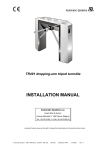
Waist Height Turnstile
User Manual & Operating Guide
www.accesscontrolequipment.co.uk
CONTENTS
1. Product Brief Introduction
2. Technical Specification
3. Functions and Features
4. Dimension and Machine Core Structure
5. Installation
6. Structure of the turnstile and working principle
7. Adjustment Instruction
8. Instruction for adjusting the function for setting the menu
9. Control board instruction diagram
10. The main control board wire connection diagram instruction
11. Service Items
12. Packing List
1
1
2
2
3
5
6
8
10
10
11
13
Appendix
Full automatic turnstile communication protocol
14
www.accesscontrolequipment.co.uk
1. Product Brief Introduction
Thank you very much for buying the intelligent full automatic tripod
turnstile product by our company. This series of turnstile adopt the unique
technology of our company----the precise photo electricity limit and gear to
orient the closure. The turnstile be unlocked and reset because of the specific
motor. The closure is very precise and stable. This series of turnstile adopt
standard electricity socket. It can read boom code card, ID card, IC card and so
on.
There is a series of turnstiles. You can choose the item and specification. They
can be used in hotel, school, metro and chamber and so on. This series is of very
high-tech. In order to guarantee it can run safely, please carefully read this
instruction!
2. Technical Specification
1) Power supply: AC220V±10%, 50Hz
2) Working voltage of motor: DC 12V
3) Rated power: 50W
4) Working temperature -15 ℃+55℃
5) Rotating speed of the motor: 850round/min
6) Dimension of the outline: 1235×280×1000mm
7) Length of the boom: 520mm
8) Largest endurance of boom: 80kg
9) Driving force of boom: 80kg
10) Working environment: outdoor and indoor.
11) Transit speed: 25~32person/minute
12) Input socket:12V electrical level signal>100ms 12V impulse signal driving
current>10mA
13) Communication socket: StandardRS232
www.accesscontrolequipment.co.uk
www.accesscontrolequipment.co.uk
3. Functions and Features
1) The integration of mechanical and electrical structure. The rotating platform
is made by specific technics. The stable mechanism can self-lock.
2) It can be bi-direction transit. The boom of the turnstile can be bi-direction or
single-direction.
3) It can self-test for malfunction, which make it easy for maintain and usage.
4) Multiple working mode for choice. The card can be read in bi-direction and
single direction. One direction can read the card, while the opposite direction
can be forbidden for transit or can be transited freely. These functions can be
realized by setting the button of the control panel or by PC software.
5) The boom can be down when the power is off and up automatically when the
power is on.
6) It can connect the Green and Red light in both direction. So the Green and Red
light can be used to remind people whether it can be transited or forbidden to
transit.
7) The flow rate calculator in both directions can show the flow rate.
8) The card reader can be installed in both direction. It support
WEIGNAD26/34 communication card reader.
9) The Rs232 socket make it feasible to connect the computer. The Internet LAN
socket can also connect it to the computer.
10) Electronic soft-start function: precise lock and unlock position photo
electricity test function.
11) The communication protocol is complete and the means of control ling is
very flexible.
12) Phonic module socket. When the card is read, the system can voice “pass” or
“forbidden to pass” by different language.
13) The system can self-detect when the boom is stopped. When the card is read
and the passenger has not passed in the specific time, the system will cancel the
transit right of this time. ( The transit time can be set by the administrant )
4. Dimension and Machine Core Structure
4.1 Dimension Figure(unit: mm)
Front View of bridge turnstile
820
1000
1000
1235
Side View of bridge turnstile
www.accesscontrolequipment.co.uk
the
Front View of bridge turnstile
Side View of bridge turnstile
4.2. Dimension of Machine Core Structure
4-M8× 20 inner
hexagonal screws
Down view of machine core
Front view of machine core
Machine core housing
Machine core box
Components for
off work tray
Flange for rotating plate
Off work tray buckle
Rotating plate
Head of boom
Boom Pin
Sealed tube
Boom
Installation figure of machine core
www.accesscontrolequipment.co.uk
5. Installation
5.1 Basement installation of the turnstile
1) check al l the spare parts according to the packing list.
2) After the whole turnstile has been installed, set the position for setting
the turnstile. Set the installing hole according to the size of the base of the
turnstile. Fasten the turnstile with four 4×M16 inflating bolts. The figure
for installing the turnstile on the ground is
as followed:
240
1235
1092.6
520
140
280
820
100
(This is the wall )
(This is the concrete floor )
Installation figure and dimension for the whole turnstile ( mm )
145
165
380
380
420
(This is the wall )
(This is the concrete floor )
Installation figure and dimension for the whole turnstile ( mm )
www.accesscontrolequipment.co.uk
3) Pack the electricity wire and the internet wire by PVC tube and embed it in the
right position by concrete.
4) Open the housing of the turnstile, fasten the net in the base of the turnstile.
5) Connect the electricity wire, al l the wire from the control panel, the socket of
control panel and the protecting wire of the system.
5.2. Installation of the boom.
1) put the boom to the installing groove of the rotating platform.
2) put the pin of the boom into the pin hole of the rotating platform.
3) when the boom pins are stalled well, fasten them with the screws.
5.3. Before using the turnstiles
1) Definition of the left or right: When facing the turnstile, the booms rotate in
the right direction, this direction is defined the left. The booms rotate in the left
direction, this direction is defined the right .
2) Input socket : +12V electricity level signal or pulse width>100ms DC Pulse
signal driving current>10mA or Rs232 signal
3) adjust for single direction transit: adjust the screws of the single direction
machine. Lock the localized boom, then the turnstile will run will in one
direction.
4) Check whether the connection is correspondent with the connection figure.
Attention: Check all the sockets, whether they are loose or whether there is wire
connect to the ground. Make sure everything is well before power and debug it
5) Check the rotating direction of the motor: After powering the system, the
boom of the turnstile will automatically begin to rotate. When user faces the
turnstile, the boom should rotate in the right direction. If not, please transfer the
two wire-connection ports.
6) Check the position of the boom. After the power is on and the boom is up, the
boom should be at the level position and locked reliably. It can not be moved by
external strength, otherwise adjust the ZERO switch. Ways: (1) open the upper
case the turnstile. (2)Loosen the screws of the arrival switch by screwdriver.
Rotate the axis and rotate the boom to the level position. Move the making the
ray of the switch point to the middle of the gap of the spot-light switch plate.
(3)fasten the screws of the arrival-switch and closer the upper cover of the
housing.
5.4 . Attention
1) Other equipments can not be installed on the turnstile. Make sure the
ground-wire safe.
2) When the turnstile is used outdoors, please install something right up the
turnstile to protect form the rain and sunlight. The turnstile should be
forbidden to be installed without anything protecting from rain and sunlight.
6. Structure of the turnstile and working principle
www.accesscontrolequipment.co.uk
6.1. Structure of the turnstile
The turnstile is composed of stainless steel housing, machine core,
control panel, card reader and display equipment and so on. The stainless
steel housing is made by separation and combination structure, which make
it easy for package and shipment.( Refer to our products for details). The
card reader is made and offered by us. The user can also install the card
reader according to his own needs. There are places form installing the card
reader and the display equipment. If the user want to choose the card reader
themselves, please tell us the specification and position of the card readers.
6.2. The basic working theory of the turnstile
After the card is read, the card reader will send a signal to the control
panel for permitting passing for the effective card. The control panel will
make the motor run. Then the boom will rotate for an angel and unlock the
system with the sound “ Di ” . Then the people can transit. After the people
have passed it and the boom has rotated for 120 degree and the calculator
will count the flow rate. For the IC or ID card reader installed in the turnstile,
the system will judge the card, if the card is effective, it will send signal to
the control panel for unlocking or locking the turnstile.
6.3.The composition of the turnstile
The turnstile can be used as a unit and as one intelligent passage. It can
also be used together, composing several passages. Meanwhile, it can also
connect to the computer. So working feedback can be sent back to the
administer.This feedback can form a report so that the administer can control
the turnstiles well.
6.4 The working mode of the turnstile
In order to facilitate the user, there are multiple working modes for the
user to chose according to the actual situation of usage.
1) Bi-directional card reading and staff limiting
2) Left can read the card , while right can be forbidden to pass
3) Right can read the card , while left can be forbidden to pass
4) Bi-directional forbidden pass
7. Adjustment Instruction
7.1. outline of the function of the system
1) Adjust the running function of the turnstile: when the card is read in the
left, the left LED indication will turn green. When the boom is moved by the
outward strength, the calculator will count the flow rate. Then the LED
direction indication will turn red. Only one person can pass the turnstile
passage for one time. If the person does not transit in the specific time, the
system will restore automatically. It works the same way in the right as the
left.
www.accesscontrolequipment.co.uk
2) Test boom-lowering function: if electricity is cut off, the boom will be
down automatically. If the power is on, the boom will rotate for several round
and then the boom will be at the level position and be locked.
7.2. Checking the system
Check the system carefully before powering the turnstile. Make sure no
part of the turnstile be jammed.
7.3. Checking with first-time electricity
Enter the menu by pressing the SET button of the control panel. Select the
P00 to adjust the rotating direction of the motor. Press the INC button, the
rotating direction should be the same with the unlocking position, otherwise
transfer the connection of the motor after exiting the menu, the turnstile will
self check the rotating direction of the motor. If the rotating direction is not
right, there will be alarm every second. At this moment, cut the electricity,
modify the connection and adjust it again. When the system begins to selfcheck the rotating direction of the motor, the two transit switches are not
effective, otherwise there will be alarm every 0.5 second. When the switch is
Warning: Do finish the above adjustment when the power is on for the
first time, otherwise the machine will be jammed and destroy the
machine!
7.4. Setting of the menu
( refer to the instruction of the setting of the menu )
7.5. Adjust the photo electricity switch for the left and right transit.
When the turnstile is unlocked, the green direction indication light will
be on. The red indication light is off, then the transit-indication light will
flash for a time. This means that the turnstile is unlocked. When the turnstile
is locked, the red direction indication is on, then the transit-indication light
will be off. This means that the turnstile is locked. Demand: the unlocking
should be even for left and right.
Attention: when the turnstile is unlocked, the transit-indication light
can not be on at the same time as the transit -permitted indication light ,
otherwise this adjustment should be repeated.
7.6. adjustment of the system function
1) Memory of reading card and transit function: when one person read the
card and another person also read card immediately after the first person, the
system will automatically memory the card-reading for this time. After the
first person transit and lock and unlock for the second person to transit.
2) Auto open when power off, and auto close when power on.
www.accesscontrolequipment.co.uk
3) when the card is read in the left: when the card is read in the left, the
turnstile will self-unlock automatically. The transit direction indication will
turn to the green light. After the person transit and the booms rotate for 120
degrees Then the photo electricity restoring switch will respond to it and
turn. Then the motor will be started and lock the turnstile. The transit
indication will turn to the red light and the calculate will count the flow rate.
It works the same way in the right!
The longest time for the transit is 10 seconds( this regulated time can be
fixed by the user, the following regulated time is supposed as 10 seconds.)
When the regulated is over and no one transit, then the turnstile will restore
and no number will be counted into the flow rate.
4) Lower the boom when electricity is cut off. When the turnstile run right
and suddenly the electricity is cut off. Then the turnstile will lower the
booms and permits the transit
7.7. Restoring function
When the card is read effectively, the boom will rotate for 15 degrees and
stop. Then the transit direction indication will turn to the green light and
permits transit. The system will restore and cancel the transit right for this
time after the regulated time. And no number will be counted into
the flow rate.
Attention: when restoring, the rotating booms in the left and the right
should be even.
7.8. Test for communication function
Set and test it according to the communication function of the software of
the upper monitor.
8. Instruction for adjusting the function for setting
the menu.
8.1. Outline of the menu.
1) LED display means the3 digital tube on control Panel from left to right.
2) 4 buttons are in too line. There is only the SET button on the first line.
There are INC, STOP, DEC, SET buttons on the second line from up to down.
SET button is for entering or exiting the menu. INC button is for increasing
the parameter. DEC button is for decreasing the parameter. STOP button is for
keep the parameter after exiting equipment. If user needs to return to the
setting status, press SET button.
8.2. setting to enter or exit the menu.
1) normal working mode. When the turnstile works, P00 appears on the LED
display. When the user faces the turnstile and adjust the function for the
turnstile and there is no need to read the card, press INC button. The boom
will turn 20 degrees in the left direction. Press SET button, then the boom will
turn 20 degrees in the right direction.
www.accesscontrolequipment.co.uk
2) When turnstile works normally, press SET button to enter the setting of
menu. P10 appears on the LED display. Press SET button again, P20 appears
on the LED display, Continue to press SET button, P30 appears. It works the
same way as other “ PXX ” till it reaches “000”. Then it exit the setting of the
menu.
3) 15 functions for setting on the menu.
P10:semi-automatic ( it is not opened normally. It can be opened according
to the clients' needs )
P11:full-automatical
P20:on-line mode
P21 off-line mode
P22: for testing the card-reading and unlocking the turnstile
P30: speed of the motor ( slow )
P31:speed of the motor(middle)
P32:speed of the motor ( fast )
Attention: there are no the three P30-P32 functions on this turnstile.
P40: time for unlocking and then locking ( short )
P41: time for unlocking and then locking ( middle )
P42: time for unlocking and then locking ( long )
P50: time for unlocking and then locking jamming (long )
P51: time for jamming ( long )
P52: time for jamming ( long )
P60: data canceling left machine ( press INC button )
P60: data canceling right machine ( press DEC button )
P70: Left can read the card , while right can be forbidden to pass
P71: Right can read the card , while left can be forbidden to pass
P72: Bi-directional forbidden pass
P73: Bi-directional card reading and staff limiting
4) Exit the setting of the menu: continue to press SET button for a cycle time.
Then “ 000 ” appears, or press STOP button exit the menu design.
8.3. Setting function instruction
1) Enter into menu, press "set" key, after hear "dip", loose "set" key, and the
screen display "P10" means already in the menu setting status, Either press
"INC" key or "DEC" key are all only can change the present setting status
function. In the status of no card reader, the arm does not run. Press "INC"
key, the screen display "P11" , and press "SET" key, the press display "P10" ,
If need to save the setting, press "SET" key, until the screen display "000" ,
which means the setting has been saved and exit the setting.
2) Under the normal working status, press twice "SET" key, enter into the
working model setting, the screen display "P20" , either press "INC" key or
"DEC" key are all only can change the present setting status function. In the
status of no card reader, the arm does not run. Press "INC" key, the screen
display "P21", and press "DEC" key, the screen display "P20". If need to
save the setting, press "SET" key, until the screen display "000", which
www.accesscontrolequipment.co.uk
means the setting has been saved and exit the setting.
3) If want to change many menu parameter setting, user can enter the menu to
change setting, and then save the setting. If user hope the equipment working
model is off line model ( the standard is card reader model ),dele the left
direct ion calculator, the menu setting as follows: Press twice "SET" key, the
screen display "P20", press twice "INC" key, the screen display "P22", and
continue to press twice "SET" key, the screen display "P40", press twice
"SET" key, the screen display "P60", press once "INC" key or "DEC" key, it
clear the left direction calculator data, and then press the "SET" key again to
save and exit the menu setting. Setting finished.
9. Control board instruction diagram
POWER
电源指示
NO PASSING
PASS
通行指示
PASSING TEST
通行试验
PASS
通行指示
STOP
停止开关
CARD READING
禁止通行 读卡指示
PASSING TEST
通行试验
After the control display board connect with the main control board, the supply
source indication and forbid pass indication are flashing, in the process of use
card reader, in the period of manage the reader, the indicator flash once, and two
of the signal indicator flash according the signal direction, meanwhile, the
forbid pass indicator not flash, after the open finished, pass indicator not flash,
forbid indicator flash. Follow up with the control board indicator test facility
working status. Before test the pass, only press" "key, cannot test the facility
status, when press"
" key,"
"pass indicator flash, the forbid pass
indicator not flash, the facility open ,the arm is turn from the"
" direction,
the passenger can pass. If do not pass, press"
"key, and the arm stop turn,"
" "pass indicator not flash, and forbid pass indicator flash. When press " ■
"key,"
"pass indicator flash, and forbid pass indicator not flash. The facility
open, arm turns in "
"direction, the passenger can pass. If do not pass, press"
" key, the arm stop turn,"
"pass indicator not flash, and forbid indicator
flash.
10. The main control board wire connection
diagram instruction
www.accesscontrolequipment.co.uk
Motor socket
1). According the electronic wire diagram, input DC+12V in the socket of the
supply source.
2). Right & red signal light separated into left and right direction traffic light, the
red light forbid pass, and the green light pass.
3). The counter separated in to Left direction and Right direction. It can
calculate the number of the passenger. And the counter delete button can
calculate the number of the passengers.
4). RS232 communication socket connect with the main control board.
5). The card reader are left direction and right direction.
6). The figure of the system connection ( Page 12 )
RS 232 communication socket
+12A
GNDA
Supply source input
AC12V
GND C/R C/L +12V
RS232
Counter clean button
GND R.+12V
GND
L. +12V
+12M
OUT1 RESET G. +12V
OUT2 RESET G. +12V
Counter socket
Red & green signal light socket
D1 DO GND +12
D1 DO GND +12
Card reader socket
The wiring diagram of tripod turnstile
11. Service Items
1). 1 year guarantee
2). Supply pay maintain after 1 year guarantee
3). 24 hours online service
* The following situations are not include guarantee
1). Broken by wrongly installed
2). Broken by improper voltage
3). The appearance of the product destroyed by wrongly installed and use
4). Broken by natural disaster
5). Overdue the guarantee
6). The service item which out of undertaking
The explaining authority of the product instruction and service article
belongs to the production factory
www.accesscontrolequipment.co.uk
Supply source
Motor socket
The wiring diagram of the system
Rs232
红&绿信号灯
Card reader
Card reader
Counter
Counter
Common
Stop
Pass
Pass
Electric leakage switch
Serial socket for computer
Voice module
Red & green signal light
Red & green signal light
Power panel
Transformer
Connector bar
NL
E
www.accesscontrolequipment.co.uk
Appendix
Full automatic turnstile communication protocol
1. Hardware protocol
Communication signal: RS232, duplex
Communication baud rate: 9600bps
Start bit: 1 bit
Stop bit: 1 bit
Data bit length: 8 data bit
Odd and Even verify code: No
2. Data package format
Source
add
Command
add
1 Byte 1 Byte
1 Bytes
Aim add
Data
length H
Data
length L
1 Byte
1 Byte
Data
Data
length rate
CRC verify CRC verify
rate L
rate H
1 Byte
Address:
PC:00H
Turnstile: FFH
Card sender: 01H
Command
00H Upload card data
01H Left open exa: FF 00 01 00 78 92
02H Right open exa: FF 00 02 00 2D C1
03H Stop
Read ( 0CH ) White list data
Write ( 0DH ) White list data
04H Left red light flash
05H Left green light flash
06H Right red light flash
07H Right green light flash
12H Emergency open
13H Close
Data length: 2 bit
Data: Data length is: 0, this data is blank
Verify Standard: CRC16 verify
www.accesscontrolequipment.co.uk
1 Byte