1
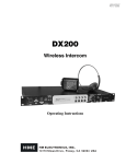
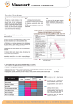
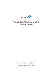
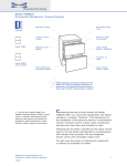
I S O L - 8
Isolate, I SO-lat, v.t. to render free from external influence
PowerStation
User Manual
Thank You
Welcome
Firstly, thank you for purchasing your ISOL-8 PowerStation we value
your custom.
We strive to design and build world class products that stand the test of
time.
By reading this manual you can gain clear understanding of its operation
and learn to care for it correctly. In turn, it will reward you with a
lifetime of outstanding performance.
Should any part of this manual or the operation of the PowerStation
not be clear to you, please do not hesitate to contact your ISOL-8
dealer. If this is not convenient, please contact ourselves directly.
To find out more about the importance of power supply in high
resolution systems, and to view our full range of mains distribution and
power conditioning solutions please visit our website:
www.isol-8.co.uk
Unpacking
WARNING! Be careful when unpacking your ISOL-8 PowerStation. It is
heavy; 19Kg. Seek assistance if necessary.
Store the packaging safely for future use. It is the ideal method of protecting it
from damage during transport.
Environment
The PowerStation is cooled by convection. Make sure room temperature air
can circulate under and around it.
Do not place objects directly on top of the unit. Allow 50mm of clear space
above the heatsinks on the side of the unit.
Do not enclose in an unventilated cupboard.
Do not place directly on carpet.
Do not place the unit near sources of heat such as radiators or in direct
sunlight.
Avoid abrasive surfaces as they may damage the finish.
A flat, smooth surface is required. A dedicated high performance equipment
platform sited away from other appliances is the optimum location.
Make sure the support for the PowerStation is capable of carrying the 19Kg
weight.
WARNING! Do not place the PowerStation near liquids, or place liquidfilled containers near the unit.
If liquid does come into contact with the unit there is serious
potential for an electric shock and / or fire hazard. Immediately pull
out the mains plug from the wall socket.
Contact your dealer to arrange an inspection before further use.
Connections
Check the voltage marked on the back of the unit matches your mains supply.
We recommend using high quality power cables to make the connections to
and from your PowerStation. ISOL-8 IsoLink cables are designed specifically
to complement the PowerStation and are ideal for this purpose.
Avoid adapters and extension cables and keep overall cable lengths as short as
is practical for best results.
The PowerStation is designed for supplying source components only, do not
connect high current loads such as power amplifiers, receivers, video
projectors, subwoofers, media servers or any other product that may require
heavy continuous or transient power.
Rear Panel View
1
3
2
1
2
3
4
5
6
7
4
5
Channel 2 output fuse
Channel 2 power outlet
Power on/off switch
IEC fused power inlet
Remote XLR4M connector
Channel 1 power outlet
Channel 1 output fuse
6
7
1
7
“Channel 1 & 2 Output fuse” The outputs are individually protected
by a ceramic 3.15A T (time delay) fuse.
2
6
“Channel 1 & 2 Power outlets” are for medium to low power
source components such as pre amplifiers, optical disc players, DACs,
tuners, phono stages or turntables. Each channel is independently
regenerated and frequency adjustable.
3
The “Power on/off switch” switches input power to the
PowerStation and must be the on position for local or remote
operation.
4
The “IEC fused power inlet” provides input power to the unit. The
unit is protected by a ceramic 3.15A T (time delay) fuse.
5
The “Remote XLR4M connector” is for remotely switching the unit
between standby and on. A 6-24V AC or DC voltage across pins 1 and
2 (any polarity) will switch the unit on, disconnecting the voltage will
return the unit to standby.
It is recommended that all connections are made and checked before applying
power.
Equipment connected to the PowerStation’s outlets should not exceed a total
continuous resistive load greater than 100VA per channel.
Operation
The ISOL-8 PowerStation provides power by firstly converting the incoming AC
mains power to smoothed DC. An independent, high purity mains waveform is
generated from this energy reservoir. The incoming mains frequency is fixed, but
the PowerStation output is free from this restriction, allowing the user to take
advantage of a higher “refresh rate” for connected equipment’s power supplies,
thus enhancing performance. We encourage experimentation with different output
frequencies to find the optimum for your system components.
Due to its low standby power consumption, the PowerStation can be left
powered on a day-to-day basis, but should be switched off if the system is not
being used for a significant period of time.
Front Panel View
Channel 1 frequency indicators
Frequency select buttons
“DSP” Display control button
Digital display
Function Indicators
“PWR” Power control button
“SET” Set control button
Channel 2 frequency indicators
1
2
3
4
5
6
7
8
1
2
3
4
5
V
T
50
6
F
P
T
DSP
PWR
SET
60
67.5
81
V
T
50
P
F
T
DSP
PWR
SET
60
67.5
81
100
100Hz
81Hz
67.5Hz
60Hz
50Hz
100
7
8
Controls and Indicators
The front panel has three main function control buttons:
3 The “DSP” button primarily controls which information is shown by the
display.
6 The “PWR” button toggles the PowerStation between standby and on.
7 The 'SET” button is primarily used to store settings.
1
2
The output frequency select buttons are labelled with the frequencies
available and are used in conjunction with the main function buttons to set
the output frequency of either channel.
8
The five vertical LEDs on each side of the PowerStation indicate the output
frequency of channel 1 and channel 2 respectively.
4
Above the control buttons is a digital display showing measured parameters
or menu information
5
Above the digital display are five function indicator LEDs
The left “T” shows channel 1 heatsink temperature is being displayed in
degC.
“V” denotes that input mains voltage is being displayed in VAC RMS.
“P” indicates the PowerStation's on/standby status.
“V” denotes that input mains frequency is being displayed in Hz.
The right “T” shows that channel 2 temperature is being displayed in degC.
Switching On and Off
Once the rear main power switch is turned on, the central power indicator “P”
will light dimly indicating standby mode. The ISOL-8 logo will scroll across the
display. The five frequency indicators on each channel sequentially illuminate briefly.
This is confirmation that the PowerStation is carrying out system checks.
To switch the unit on, briefly push the “PWR” button.
The central power indicator “P” will now flash and the display will briefly show
“ON”. The display will then show “1” referring to channel 1 and the channel 1
50Hz indicator will light. Channel one is now enabled and mains power at 50Hz is
generated. After one second the display will then show “2” referring to channel 2
and the channel 2 50Hz indicator will light brightly. Channel two is now enabled
and mains power at 50Hz is generated. A further second later the “V” indicator
will light and the display will show the incoming RMS mains voltage. This is the
factory default setting.
To return the PowerStation to standby press “PWR” again.
Changing the Display
Pressing the “DSP” button will toggle the display through mains input Voltage to
mains input Frequency to Temperature (right channel) to Temperature (left
channel) and back to Voltage. The function indicators show which parameter is
being displayed.
Setting Output Frequency
We encourage experimentation with different output frequencies to find the
optimum setting for your system components.
To set the output frequency of both channels together, press the “SET” button
once. The display will show “ALL”. Next press the chosen frequency button that you
wish to output. The frequency of both outputs will be indicated by the respective
frequency indicators on either channel.
You can experiment with which setting you prefer for as long as required. To store
the setting press and hold the “SET” button.“E2P” will be shown by the display
whilst the setting is saved to memory. The display will now revert to the previously
displayed information. The “SET” button can now be released.
To alter the output frequency of each channel separately, press the “SET” button
twice in succession. The display will show “CH1”. Now press the chosen frequency
button that you wish to output. The channel 1 frequency indicator LEDs will
confirm the frequency selected.You can experiment with which setting you prefer
for as long as required.
Save the setting by press and holding the “SET” button (as above) or to set channel
two press the “SET” button again: the display will now show “CH2”. Next press
the chosen frequency button that you wish to output. The channel 2 frequency
indicator LEDs will confirm the frequency selected.
You can also go directly to channel 2 frequency setting by pressing the “SET”
button three times. Remember you can save your settings at any step by holding
down the “SET” button as detailed above.
Once in frequency “SET” mode, even if no changes are made, press and hold
“SET” to get back to normal display mode.
The PowerStation will always revert to the settings which have last been saved to
memory when turned on.
Note that if a 50Hz synchronous motor turntable is connected to a PowerStation
outlet, selecting 67.5 Hz will increase the turntable speed to 45rpm. Similarly if a
60Hz synchronous motor turntable is connected to a PowerStation outlet, selecting
81 Hz will increase the turntable speed to 45rpm.
Night Mode
Night Mode switches off the main display and dims the indicator LED's for
minimum visual impact. To enter Night Mode press and hold the “DSP” button for
two seconds. To revert to normal display mode press the “DSP” button briefly.
Over Temperature
If the ambient temperature is too high to allow adequate cooling, or the connected
load is inappropriate, the PowerStation will shut down if either channel heatsink
temperature exceeds 62 degC.
The display will momentarily show “OFF” then “HOT”. The left or right “T”
indicator will flash indicating which channel was over temperature. The
PowerStation can not be turned on again from the front “PWR” button.
To reset, take appropriate steps to ensure the condition cannot be repeated. Check
that the connected load is suitable and that all ventilation requirements are met.
Allow an appropriate time for the unit to cool. Turn off the rear panel Main Switch
and wait ten seconds. Switch the rear panel switch back on to enter standby. The
PowerStation can then be switched on and should then operate normally.
Output Fuses
All five frequency indicators flashing simultaneously indicates that the output fuse
for that channel has blown. Check that the connected equipment functioning
correctly and are appropriate for the PowerStation’s output capacity. Fuses can
also age and occasionally fail unexpectedly. Turn off the PowerStation using the
rear panel switch, disconnect from the supply and replace the appropriate fuse
with one of an identical type.
WARNING! Failure to replace the fuse with the same type and rating
will invalidate the warranty and may result in an electric shock and/or
fire hazard.
If you are in any doubt about any aspect of installation or operation, please consult
your dealer, a qualified electrician or contact ISOL-8 directly for advice.
Cleaning
Dust the unit regularly with a soft cloth or soft brush. For more stubborn marks
use a slightly damp cloth with a very small amount of mild detergent such as
washing up liquid.
Do not use a wet cloth. Other cleaning or polishing agents should not be used.
Never use abrasives or alcohol based agents, they will harm the surface finish.
Do not allow the unit to become wet when cleaning.
Specification (subject to change)
Number of outlets:
Dimensions:
Weight:
Input Voltage:
Standby power consumption:
Maximum power consumption:
Output voltage:
Output frequency:
Output frequency accuracy:
2 (1 per channel)
445*145*420mm (W*H*D)
19Kg
200-260VAC
6VA
350VA (Full load)
230VRMS +/- 10%
50, 60, 67.5, 81 and 100Hz
+/- 0.05%
Fuses
Outputs 1 & 2
Mains Input:
3.15A T Ceramic 20mm fuse
3.15A T Ceramic 20mm fuse
Returns
Should it be necessary for your PowerStation to be serviced, please send it in the
original packaging to your dealer. If this is not possible please contact us to obtain
a Return Authorisation Number. Returns without this number will not be
accepted. If it is not returned to us in its original packaging, ISOL-8 reserve the
right to make a nominal charge for packaging by return.
Disposal and Recycling
At the end of the units working life it must be disposed of correctly. It is made to
the highest standards with materials which can be recycled wherever possible. Do
not dispose to landfill, contact your dealer or ISOL-8 for information regarding
return for correct disposal.
Declarations
Information given in this document is correct at the time of printing. Our policy of
continuous development means any changes might not be indicated in the
specification.
This product is guaranteed against defects in material and workmanship for 5
years from the date of purchase in the UK only. Proof of purchase is required.
The Guarantee is not transferable and is offered to the original purchaser only.
This guarantee does not limit your statutory rights within the country of
purchase.
The PowerStation records operational data for factory fault finding. Failure to
comply with any of the above instructions during installation or operation will
render the manufacturer’s warranty null and void.
Marking by the “CE” symbol indicates compliance of this device with the EMC
(Electromagnetic Compatibility) and LVD (Low Voltage Directive) standards of the
European Community
Isol-8 Teknologies Ltd
PO Box 56402
London SE3 7WQ
fax: +44 (0) 20 8856 0616
email: [email protected]
Please visit our web site: www.isol-8.co.uk
© Isol-8 Teknologies 2010