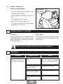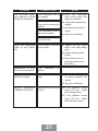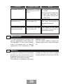
1
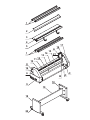
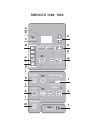
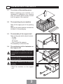
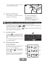
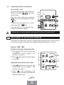
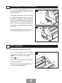
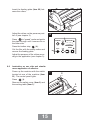
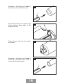
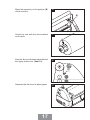
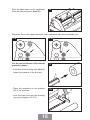
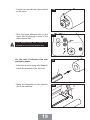
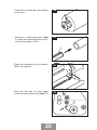
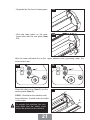
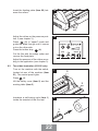
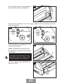
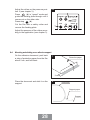
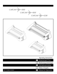
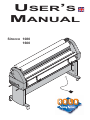
USER’S
MANUAL
Sirocco 1080
1600
E MEA
S.
C
439000
MOD
MP
Y
READ
SURE
PRES 4 5
3
1 2
ARD
FORW
1234
5 6789
10
D
SPEE
STOP
RSE
REVE
ER
POW
KALA S.A.S.
Parc de l'Ecotay
35 410 Nouvoitou - France
Tel. : +33 (0)2 99 37 64 64
Fax : +33 (0)2 99 37 64 65
www.kala.fr - [email protected]
1
2
3
4
5
A
10
12
14
15
21
READY
MEAS.
MODE
C
439000
11
13
17
MP
1
16
RE
PRESSU 4 5
3
1 2
D
FORWAR
1234
5 678910
SPEED
STOP
E
REVERS
POWER
8
16
C
6
B
18
9
19
18
20
D
Composants de la plastifieuse
Rep Désignation
1
2
3
4
5
6
7
8
9
10
11
12
13
14
15
16
17
18
19
20
21
Axes autobloquants
Carter de protection plexiglas
Table de travail
Butée latérale
Paniers support document
Capot gauche
Capot droit
Poignée supérieure de réglage
de la tension des films
Poignée inférieure de réglage
de la tension des films
Rouleau laminateur supérieur
Rouleau laminateur inférieur
Barre de tension supérieure
Barre de tension inférieure
Rouleau chauffant supérieur
Rouleau chauffant inférieur
Bouton d'arrêt d'urgence
Panneau de commande
Côtés du stand
Cloison de stand
Roulettes
Interrupteur Marche / Arrêt
Bauteile des Laminators
Pos. Bezeichnung
1
2
3
4
5
6
7
8
9
10
11
12
13
14
15
16
17
18
19
20
21
selbstblockierende Auf- bzw.
Abwickelachsen
Schutzabdeckung
aus
PlexiglasPaniers support
Anlegetisch
Seitenanschlag
Dokumentenhalter
Abdeckung links
Abdeckung rechts
Einstellknopf obere Folienspannung
Einstellknopf untere Folienspannung
obere Laminatorwalze
untere Laminatorwalze
obere Spannleiste
untere Spannleiste
oberer Heizzylinder
unterer Heizzylinder
Notausschalter
Berührungsfeld-Steuerpult
Untergestell-Seitenteile
Untergestell-Mittelteil
Laufrollen
Ein-Ausschalter
Parts list of the laminator
Item Designation
1
2
3
4
5
6
7
8
9
10
11
12
13
14
15
16
17
18
19
20
21
Self-locking axles
Plexiglass safety cover
Working table
Lateral stop
Document support trays
Left-hand cover guard
Right-hand cover guard
Upper Film tension adjustment handles
Lower Film tension adjustment handles
Upper laminator roller
Lower laminator roller
Upper tension bar
Lower tension bar
Upper heating roller
Lower heating roller
Emergency stop button
Control panel
Sides of support unit
Support unit panel
Small wheels
On/Off switch
Componenti della plastificatrice
Rif.
1
2
3
4
5
6
7
8
9
10
11
12
13
14
15
16
17
18
19
20
21
Descrizione
Assi autobloccanti
Carter di protezione plexiglas
Piano di alimentazione
Arresto laterale
Vassoi supporto documento
Calotta sinistra
Calotta destra
Manopola superiore di regolazione della tensione dei film
Manopola inferiore di regolazione della tensione dei film
Rullo laminatore superiore
Rullo laminatore inferiore
Barra di tensione superiore
Barra di tensione inferiore
Rullo riscaldante superiore
Rullo riscaldante inferiore
Pulsante di arresto d'emergenza
Pannello di controllo
Lati del supporto
Divisorio del supporto
Rotelle
Interruttore acceso/spento
Componentes de la plastificadora
Ref
1
2
3
4
5
6
7
8
9
10
11
12
13
14
15
16
17
18
19
20
21
Designación
Ejes autoblocantes
Cárter de protección plexiglás
Mesa de trabajo
Tope laterale
Cesto soporte documento
Cubierta izquierda
Cubierta derecha
Puño superior de ajuste de
la tensión de las peliculas
Puño inferior de ajuste de la
tensión de las peliculas
Rodillos laminadores superior
Rodillos laminadores inferior
Barra de tensión superior
Barra de tensión inferior
Rodillos calentadores superior
Rodillos calentadores inferior
Botón de parada de emergencia
Cuadro de mandos
Lados del soporte
Tabique del soporte
Ruedecillas
Interruptor Marcha/Parada
SIROCCO 1080, 1600
a
b
c
n
READY
d
MODE
o
MEAS.
p
C
q
MP 439000
e
f
g
i
h
FORWARD
j
k
PRESSURE
1 2 3 4 5
r
1 2 3 4 5 6 7 8 910
STOP
SPEED
s
l
m
REVERSE
t
POWER
Panneau de commande
Rep Désignation
a
b
c
d
e
f
g
h
i
j
k
l
m
n
o
p
q
r
s
t
Affichage digital de la température.
Voyant Ready
Sélection des mémoires et du mode
de plastification
Visualisation du programme actif
Mode veille (plastification à chaud)
Visualisation du mode plastification à froid
Mise en route des ventilateurs
Marche avant des rouleaux + montée
du rouleau supérieur (S1080 / S1600)
Commande par pédale
Visualisation du mode "écartement
des rouleaux"
Arrêt des moteurs
Sélection écartement des rouleaux
Marche arrière des rouleaux + descente
du rouleau supérieur (S1080 / S1600)
Voyant rouge allumé visualise la mise
en chauffe des rouleaux
Sélection des rouleaux chauffants
Visualisation de la température réelle
des rouleaux
Réglage de la température
Affichage digital de la pression ou de la
vitesse des rouleaux (S1080 / S1600)
Réglage de la vitesse (S1080 / S1600)
Mise en veille
Control panel
Item Designation
a
b
c
d
e
f
g
h
i
j
k
l
m
n
o
p
q
r
s
t
Berührungsfeld-Steuerpult
Pos. Bezeichnung
a
b
c
d
e
f
g
h
i
j
k
l
m
n
o
p
q
r
s
t
digitale Temperaturanzeige
Anzeige "Betriebsbereit"
Auswahl Speicher und Betriebsart
Anzeige aktives Programm
Stand by (Heißlaminieren)
Betriebsanzeige "Kaltlaminieren"
Kühlventilatoren einschalten
Walzen vorwärts laufen lassen und
obere Walze hochfahren (S1080/ S1600)
Fußschalter
Betriebsanzeige "Walzen öffnen"
Motor abschalten
Auswahl Walzenöffnung
Walzen rückwärts laufen lassen und
obere Walze senken (S1080 / S1600)
Einstellungsanzeige "Heizzylinder eingeschaltet", die rote Diode leuchtet
Auswahl der Heizzylinder
Anzeige der echten Walzentemperatur
Temperatureinstellung
digitale Druckanzeige oder Walzengeschwindigkeitsanzeige (S1080/ S1600)
Geschwindigkeitseinstellung
(S1080/S1600)
Hauptschalter
Digital temperature display
Ready light
Selection of the memories and of the
mode of lamination
Visualisation of the active program
Stand-by position (hot lamination)
Visualisation of the mode cold lamination
Starting of the ventilators
Forward motion of the rollers + rise
of the upper roller (S1080 / S1600)
Using pedal switch
Visualisation of the mode “spacing of
the rollers”
Motor stop
Selection spacing of the rollers
Reverse motion of the rollers + descent
of the upper roller (S1080 / S1600)
Red light on indicates rollers are heating
Control of heating cylinder(s)
Visualisation of the real temperature
of the rollers
Temperature adjustment
Roller pressure and speed digital
display (S1080 / S1600)
Speed adjustment (S1080 / S1600)
Stand-by switch
Pannello di controllo
Rif.
a
b
c
d
e
f
g
h
i
j
k
l
m
n
o
p
q
r
s
t
Descrizione
Display digitale della temperatura
Spia ready
Selezione delle memorie e della
modalità di plastificazione
Visualizzazione del programma attivo
Modalità standby (plastificazione a caldo)
Visualizzazione della modalità plastificazione a freddo
Avviamento dei ventilatori
Marcia in avanti dei rulli + salita del
rullo superiore (S1080 / S1600)
Comando tramite pedale
Visualizzazione della modalità "distanza dei rulli"
Arresto dei motori
Selezione distanza dei rulli
Marcia indietro dei rulli + discesa del
rullo superiore (S1080 / S1600)
Spia rossa accesa visualizza il riscaldamento dei rulli
Selezione dei rulli riscaldanti
Visualizzazione della temperatura
reale dei rulli
Regolazione della temperatura
Display digitale della pressione o della
velocità dei rulli (S1080 / S1600)
Regolazione della velocità (S1080/ S1600)
Messa in standby
Cuadros de mandos
Ref
a
b
c
d
e
f
g
h
i
j
k
l
m
n
o
p
q
r
s
t
Designación
Visualización de la temperatura
Señal READY
Selección de las memorias y del
modo de plastificación
Visualización programa activo
Modo stand-by (laminación en caliente)
Visualización del modo de laminación
en frío
Conexión de los ventiladores
Marcha delantera de los rodillos y descenso del rodillo superior (S1080 / S1600)
Control mediante pedal
Visualización del modo “distancia de
los rollos”
Parada de los motores
Selección distancia de los rodillos
Marcha atrás de los rodillos y descenso
del rodillo superior (S1080 / S1600)
Piloto rojo enciendido visualiza la puesta en calentamiento de los rodillos
Visualización de la temperatura real
de los rodillos
Ajuste de la temperatura
Visualización digital de la presión o de la
velocidad de los rodillos (S1080 / S1600)
Ajuste de la velocidad (S1080 / S1600)
Puesta en vela
Déclaration de conformité
KALA S.A.S.
Parc de l’Ecotay
35 410 NOUVOITOU
FRANCE.
Déclare que le produit suivant :
Modèle : SIROCCO est conforme aux exigences
suivantes
Voltage 220-240V :
• Directive machines : (98/37 CEE) incluant :
• Directive basse tension (73/23 CEE) selon la
norme EN 60204 - 1 (1997)
• Directive Compatibilité Electromagnétique
(89/336 CEE) selon la norme EN 55014,
Edition 1993 et EN 55014-2 Edition 1997.
Toujours à la recherche du progrès, nous nous réservons le droit de modifier sans préavis les modèles ainsi que les équipements et leurs caractéristiques techniques.
Declaration of conformity
KALA S.A.S.
Parc de l’Ecotay
35 410 NOUVOITOU
FRANCE.
Declares that the following product:
SIROCCO Model conforms to the following requirements
Voltage 220-240V:
• Machine Directive : (98/37 EEC) :
• Low voltage Directive (73/23 EEC) according
to the EN 60204 – 1 (1997)
• Electromagnetic compatibility Directive (89/336
EEC) according to the EN 55014, Edition 1993
and EN 55014-2 Edition 1997.
Always seeking to make progress, we reserve ourselves the right to change without notice the models as well as the equipment and their technical features.
Konformitätsbestätigung
KALA S.A.S.
Parc de l’Ecotay
35 410 NOUVOITOU
FRANCE.
bestätigt, daß folgendes Produkt:
Modell SIROCCO folgende Forderungen erfüllt
Spannung 220-240V:
• Maschinenrichtlinie: (98/37 CEE) :
• Niederspannungs-Richtlinie
(73/23
CEE)
gemäss EN 60204 – 1 (1997)
• Richtlinie bezüglich der elektromagnetischen
Verträglichkeit (89/336 CEE) gemäss EN 55014,
Ausgabe 1993 und EN 55014-2 Ausgabe 1997
Sempre alla ricerca di innovazioni, ci riserviamo il diritto di modificare senza preavviso i modelli, le apparecchiature e le loro caratteristiche tecniche.
Dichiarazione di conformità
KALA S.A.S.
Parc de l’Ecotay
35 410 NOUVOITOU
FRANCE.
Dichiara che il seguente prodotto:
Modello: SIROCCO è conforme alle seguenti direttive
Tensione 220-240V:
• Direttiva macchina: (98/37 CEE) :
• Direttiva bassa tensione (73/23 CEE) conformemente alla normativa EN 60204 - 1 (1997)
• Direttiva Compatibilità Elettromagnetica (89/336
CEE) conformemente alla normativa EN 55014,
Edizione 1993 e EN 55014-2 Edizione 1997
Sempre alla ricerca di innovazioni, ci riserviamo il diritto di modificare senza preavviso i modelli, le apparecchiature e le loro caratteristiche tecniche.
Declaración de conformidad
KALA S.A.S.
Parc de l’Ecotay
35 410 NOUVOITOU
FRANCE.
Declara que el producto siguiente:
Máquina modelo SIROCCO está en conformidad
con las exigencias siguientes
Voltaje 220 - 240V:
• Directiva máquina: (98/37 CEE) :
• Directiva baja tensión (73/23 CEE) según la
norma EN 60204 - 1 (1997)
• Directiva Compatibilidad Electromagnética
(89/336 CEE) según las normas EN 55014,
Edición 1993 y EN 55014-2
Siempre en pos del mayor progreso, nos reservamos el derecho de modificar sin aviso previo las características y los equipos técnicos de los modelos.
Garantie
Votre Sirocco est garantie contre tous défauts de
matériaux et de fabrication pendant une période d'un
an après la date d'achat. En cas de défauts de matériaux ou de fabrication, la société ayant vendu l'appareil réparera celui-ci dans ses ateliers ou le retournera
au fabricant. Il n'existe aucune garantie autre que
celle qui vient d'être mentionnée ci-dessus. Cette
garantie ne couvre pas les dommages particuliers ou
résultants de causes indirectes, qu'ils soient ou non
prévisibles. La garantie ne couvre pas les mauvaises
utilisations de la machine.
Réglementation de retour :
Si votre Sirocco ne fonctionne pas bien, relisez d'abord les instructions. Si le fonctionnement défectueux
ne peut-être corrigé, demandez conseil à votre fournisseur. Assurez-vous que le numéro de série et la
date d'achat de votre appareil soient à portée de main.
Si vous devez retourner la machine au fournisseur,
elle devra être dans son emballage d’origine. Les
dommages de transport résultants d'un emballage
défectueux ne sont pas couverts selon les termes de
cette garantie.
Warranty
Your Sirocco is guaranteed against all defects of materials and manufacturing for a period of one year from
the date of purchase. In the event of defects of materials or manufacturing, the company which sold the
instrument will repair it or it will be returned to the
manufacturer. There is no warranty other than the one
mentioned above. This warranty does not cover individual damage or damage resulting from indirect causes, whether foreseeable or not. The warranty does not
cover incorrect use of the machine.
Return regulations:
If your Sirocco does not fwork correctly, firstly read the
instructions again. If the defective operation cannot be
corrected, consult your supplier. Make sure that the
series number and the date of purchase of your
machine are to hand, if you have to return the machine to the supplier. Damage during transport resulting
from defective packaging is not covered under the
terms of this guarantee.
Garantie
Ihre Sirocco Maschine weist vom Kaufdatum ab eine einjährige Garantie gegen jeglichen Material- und
Herstellungsfehler
auf.
Falls
Materialoder
Herstellungsfehler auftreten sollten, so wird die Firma, die
das Gerät verkauft hat, dieses in ihren eigenen
Werkstätten reparieren oder an den Hersteller zurücksenden. Es gibt keinerlei andere Garantie als die obengenannte. Diese Garantie deckt nicht die besonderen
Schäden oder die Schäden, die indirekt verursacht worden
sind, ob diese vorhersehbar sind oder nicht. Die Garantie
deckt nicht die falschen Anwendungen der Maschine.
Rücksendungs-Regelung:
Falls Ihre Sirocco nicht richtig funktionieren sollte,
lesen Sie zuerst noch einmal die Anweisungen durch.
Wenn das Problem nicht behoben werden kann, fragen Sie Ihren Händler um Rat. Stellen Sie sicher, daß
die Seriennummer und das Einkaufsdatum Ihres
Geräts griffbereit sind, falls Sie die Maschine zum
Händler
zurücksenden
müssen.
Die
Transportschäden, die von einer fehlerhaften
Verpackung herrühren, stellen keinen Garantiefall dar.
Garanzia
La garanzia della vostra Sirocco copre tutti i difetti di
materiale e di fabbricazione per un anno a partire dalla
data di acquisto. In caso di difetti di materiale o di fabbricazione, la società che ha venduto la macchina
provvederà a ripararla presso il proprio servizio assistenza o a restituirla al fabbricante. Non esiste altra
garanzia oltre a quella sopra citata. Tale garanzia non
copre i danni speciali o dovuti a cause indirette, indipendentemente dal fatto che siano o meno prevedibili. La garanzia non copre i danni legati ad un cattivo
uso della macchina.
Disposizioni per la restituzione:
Se la vostra Sirocco non funziona correttamente, si
consiglia innanzitutto di rileggere il libretto d’istruzioni.
Qualora non fosse possibile correggere il funzionamento difettoso, chiedete consiglio al vostro fornitore.
Accertatevi di avere sotto mano il numero di serie della
macchina e la data di acquisto nel caso in cui dobbiate restituire la macchina al fornitore. I danni da trasporto dovuti ad un imballaggio difettoso non sono coperti
ai sensi delle condizioni della presente garanzia.
Garantía
La máquina Sirocco está garantizada contra todos los
defectos de material y fabricación durante un periodo
de un año después de la fecha de compra. En caso de
defectos de material o fabricación, la sociedad que ha
vendido el aparato lo reparará en sus talleres o lo
devolverá al fabricante, no habiendo ninguna otra
garantía. Estas garantía no cubre los daños particulares o que resulten de causas indirectas, previsibles o
imprevisibles. La garantía no cubre la mala utilización
de la máquina.
Reglamentación de devolución:
Si su máquina Sirocco no funciona bien, lea de nuevo
las instrucciones. Si el funcionamiento defectuoso no
puede corregirse con éstas, solicite consejo a su proveedor. Cerciórese de que el número de serie y la
fecha de compra del aparato están al alcance de la
mano, si debe devolver la máquina al proveedor. Los
daños de transporte que resulten de un embalaje
defectuoso no están cubiertos por esta garantía.
SUMMARY
1
THE
RECEPTION OF YOUR SIROCCO
The choice of your working space
The unpacking of your machine
The assembly of the support unit
The positioning of the laminator on the support unit
The start-up kit of films
PAGE 3
OF THE SPEED AND OF THE TEMPERATURE OF THE ROLLERS
2-1 Automatic stand-by
2-2 Programming of the speed
2-3 Programming of the temperature
PAGE 4
ADJUSTMENT OF THE
ADJUSTMENT OF THE
HOT LAMINATION
ROLLERS PRESSURE
PAGE 5
FILMS TENSION
PAGE 6
1-1
1-2
1-3
1-4
1-5
2
3
4
5
PROGRAMMING
55-2
5-3
6
9
10
11
12
13
3
3
3
3
4
PAGE 4
PAGE 4
PAGE 5
PAGE 6
PAGE 6
PAGE 10
PAGE 10
COLD
PAGE 11
6-1
6-2
PAGE 11
PAGE 15
6-3
6-4
6-5
7
8
Feeding of the film Sirocco 1600
Change of rollers
Ventilator use
PAGE
PAGE
PAGE
PAGE
PAGE
LAMINATION
Lamination on one side only S.1600
Lamination on one side and simultaneous adhesive
application S.1600
Recto-Verso lamination S.1600
Mounting and sticking on an adhesive support
Simplification of use
PAGE 22
PAGE 28
PAGE 30
ADJUSTMENTS
TECHNICAL CHARACTERISTICS
PAGE 33
8-1
8-2
PAGE 34
PAGE 34
SIROCCO 1080
SIROCCO 1600
PAGE 34
MAINTENANCE AND
PAGE 35
9-1
9-2
PAGE 35
PAGE 36
SAFETY
Maintenance
Safety : weekly test
FILM REELS CONDITIONING
PAGE 36
INCIDENTS
MAINTENANCE
DISPOSAL
PAGE 36
PAGE 38
PAGE 38
CHECK
THAT
:
The tension of your machine corresponds with the tension of your
electrical network.
The supply connections must be
congruent with the installation
rules of the standard NFC 15 100.
The machine’s supply needs to be
placed at disposal of a stand base
of a compatible electric socket CEI
60309-1.
INSTALL THE SIROCCO
ON A STABLE WORKING BASE, CLOSE TO AN EASILY
ACCESSIBLE ELECTRIC SOCKET.
Do not touch the socket with damp
hands.
The machine should be installed in
a well-ventilated place.
To unplug the machine, disconnect
the plug without pulling on the supply lead.
The longitudinal knifes should not
be used with documents which are
not laminated paper (rigid support...).
To prevent electric shocks, do not
use this laminating machine close
to water.
Make a working area behind the
machine.
Do not spill water on the machine,
the supply lead or the electric socket.
Do not use the machine if the supply lead is damaged.
Do not leave the electric lead in
contact with a warm surface.
2
Disconnect the general supply of
the machine with the switch (item
21) after each use.
During the assembly of the machine, be careful with the quartz heater and the ground areas (vibrations). If the machine must be disassembled, call a technician.
1
1-1
THE
RECEPTION OF YOUR SIROCCO
The choice of the working space
Before unpacking your machine, it is
necessary to determine your working
area. You should have an easy access
to all the parts of the machine.
1-2
The unpacking of your machine
Take off the upper part of the packing
case.
Remove the axles and the accessories
included in the packaging.
1-3
The assembly of the support unit
Take out the parts which should include :
- 2 sides
- 1 panel
- 10 screws
- One 10 mm flat spanner
The assembly is done like this.
1-4
The positioning of the laminator on
the support unit
The machine is heavy. A minimum
of 4 people is required for this operation.
1
Do not hold the machine by the lateral cover guards.
Hold the machine by its carrying
handles.
• Place the machine on the support
unit.
3
2
• Fix the assembly with the screws
supplied with the support.
1-5
Start up kit (S.1600 only)
In the packing, you will find a complete start up kit containing :
2
3
- Two rollers of thermal film
- One roller of assembly film
(double-sided)
- One roller of cold adhesive film
- Two chucks in cardboard
PROGRAMMING OF THE SPEED AND THE TEMPERATURE OF THE ROLLERS
The programs M1, M2, M3 and M4 can be selected by the operator.
To activate a program, Press MODE or
(c) buttons continually until the light corresponding to the required program comes on.
When a cold lamination, (the button
only the speed can be programmed.
2-1
(f) lights on the Sirocco 1080 and 1600),
Automatic stand-by
The light
(e) indicates that the
machine has been automatically switched to stand-by after 30 mn of nonuse.
The stand-by temperature can be set
in the range 40-80°C.
2-2
For security reasons, the transition
from cold to hot mode desactivates
the heating rollers. Before hot lamination, it is necessary to start them up
again by pressing
(o).
Programming of the speed
Sirocco 1080, 1600
To set up the speed, the light (j) must
be off. If not, press
(l).
Adjust the speed of the rollers by pressing the
and
keys (s) of the
control panel.
The last value entered automatically
replaces the previous stored value.
h
FORWARD
PRESSURE
1 2 3 4 5
i
j
k
1 2 3 4 5 6 7 8 910
STOP
SPEED
s
l
m
REVERSE
t
POWER
4
r
2-3
Programming of the temperature
Sirocco 1080, 1600
Start the roller heating by pressing
(o) and it is indicated by the light
(n).
To know the temperature of a roller,
press the button MEAS. (p).
If the light (b) is on, the required temperature is obtained (ready).
a
b
c
n
READY
d
MODE
o
MEAS.
p
C
e
f
g
q
MP 439000
Adjust the temperature of the rollers by
pressing the keys
(q) of the
control panel.
The last value entered replaces automatically the previous stored value.
3
ADJUSTMENT
OF THE ROLLERS PRESSURE
The Sirocco is fitted with a device for adjusting the space and the roller pressure.
This device permits to laminate thick supports (Maximal thickness : 25 mm).
Sirocco 1080, 1600
Adjustment of the space between the rollers :
1- Press
(l) if the light (j) and the light
"PRESSURE" are not lighted ; the
function is activated.
h
2- Press
(h) until the required space
is obtained.
i
j
k
Adjustment of the pressure of the rollers :
1- Press
(l) if the light (j) and the light
"PRESSURE" are not lighted ; the
function is activated.
2- Press
(m) continuously until
display on control panel indicates the
required pressure (r) :
1 2 3 4 5
5
FORWARD
PRESSURE
1 2 3 4 5
r
1 2 3 4 5 6 7 8 910
STOP
SPEED
s
l
m
REVERSE
t
POWER
4
ADJUSTMENT
OF THE FILMS TENSION
The handles (Items 8 and 9) are used
to adjust the tension of the films on the
self-locking axles.
During the lamination, the film should
be sufficiently tight to ensure a perfect
lamination. However, the film should
not be stretched excessively. Only by
testing can you find the suitable tension. If some folds appear at level of
the rollers, increase lightly the tension
of the film.
1
8
9
2
To increase the tension of the film, turn
the handles (Item 8 or 9) clockwise.
LAMINATION
Feeding of the film Sirocco 1600
Turn on the machine with the switch
located at the back of the machine
(Item 21).The control panel lights.
Press
1
2
(t).
Adjust the temperature of the lamination (see chapter 3).
READY
MEAS
3
.
MODE
C
439000
5-1
HOT
MP
5
URE
PRESS 4 5
3
1 2
RD
Remove the safety cover (Item 2) and
the working table (Item 3).
6
FORWA
1234
5 678910
SPEED
STOP
SE
REVER
POWE
R
Introduce a self-locking axle (Item 1)
inside the mandrel of the film reel.
2
1
Place the assembly on the position (A)
of the machine.
3
A
Y
READ
MEAS
.
MODE
MP
439000
C
SURE
PRES 4 5
3
1 2
ARD
FORW
1234
5 6789
10
SPEE
STOP
RSE
REVE
Centre the reel with the rules marked
on the axle.
4
10
Introduce a self-locking axle (Item 1)
inside the mandrel of the film reel.
5
1
7
D
Y
READ
MEAS
.
MODE
C
439000
6
C
MP
Place the assembly on the position (C)
of the machine.
SURE
PRES 4 5
3
1 2
ARD
FORW
1234
5 6789
10
SPEE
D
STOP
RSE
REVE
POWE
Centre the reel with the rules marked
on the axle.
7
10
Place the film of the upper roller on the
heating rollers (adhesive side facing
towards you) by passing besides of the
lower tension bar.
8
Place the film of the lower roller on the
upper film (adhesive side facing
towards you) by passing besides of the
lower tension bar.
Respect the direction of the film according to its size :
- Diagram 8 : The adhesive is outside the rollers.
- Diagram 9 : The adhesive is inside
the rollers.
The temperature of the rollers must
be sufficiently important to stick the
films.
8
9
R
Place the safety cover (Item 2) and the
working table (Item 3).
10
2
Y
READ
To operate the machine, the working table and the safety cover must
be in place on the machine.
Insert the feeding plate (Item 22) between the rollers.
3
.
MEAS
MODE
MP
439000
C
SURE
PRES 4 5
3
1 2
ARD
FORW
1234
5 6789
10
D
SPEE
STOP
RSE
REVE
POWE
R
11
22
Adjust the rollers on the pressure position 1 (see chapter 3).
Press
(h),“speed” mode and guide
the feeding plate through until it comes
out on the other side.
Press stop
(k).
Cut the film with a safety cutter and
recover the feeding plate.
12
FORWARD
1 2 3 4 5 6 7 8 910
STOP
Adjust the pressure of the rollers
according to the application (see chapter 3).
Remove pressure from the rollers
before switching the machine off.
9
PRESSURE
1 2 3 4 5
SPEED
5-2
Changing of the film rollers
Stop the machine by pressing the button stop
or
(k).
1
24
Cut the films of the reels with a safety
cutter (Item 24).
Not to damage the heating rollers
during this operation.
Remove the worned reels and replace
them with the new ones.
2
Place the new films in such a way that
its extremities stick to the old films in
contact with the heating rollers.
Press
Use of the ventilators
The ventilators are recommended for
cooling the films during the lamination
of the documents with thick films.
The ventilators are started or stopped
by pressing the key
(g).
10
1
S1080 / S1600
C
MP 439000
5-3
(h).
LAMINATION
Lamination on one side
Turn on the machine with the switch
located at the back of the machine
(Item 21). The control panel lights.
Press
1
2
(t).
Remove the safety cover (Item 2) and
the working table (Item 3).
READY
MEAS
3
.
MODE
C
439000
URE
PRESS 4 5
3
1 2
RD
FORWA
1234
5 678910
SPEED
STOP
SE
REVER
POWE
Introduce a self-locking axle (Item 1)
inside the mandrel of the film reel.
R
2
1
Place the assembly on the position (A)
of the machine (The film base paper
towards the top).
3
A
Y
READ
MEAS
.
MODE
439000
C
MP
6-1
COLD
MP
6
SURE
PRES 4 5
3
1 2
ARD
FORW
1234
5 6789
10
SPEE
STOP
RSE
REVE
Centre the reel with the rules marked
on the axle.
4
10
11
D
Introduce a self-locking axle (Item 1)
inside the cardboard tube used to
recover the film base paper.
5
1
Place the assembly on the position (B)
of the machine.
6
B
READY
MEAS.
MODE
MP
439000
C
URE
PRESS 4 5
3
FORWA
1 2
RD
1234
5 678910
SPEED
STOP
SE
REVER
POWER
Centre the reel with the rules marked
on the axle.
7
10
Pass the film and its base paper behind
the upper tension bar (Item 10).
8
10
12
Separate the film from its base paper.
9
Stick the protective paper on the cardboard tube with the reel pistol (Item
23).
10
23
Place the film on the upper laminator reel (adhesive side facing towards you).
11 A
11
Introduce a self-locking axle (Item 1)
inside the mandrel of the paper reel
(not supplied in the start-up kit).
12
The paper reel should be wider than
the film reel.
13
B
1
13
Y
READ
MEAS
.
MODE
439000
C
C
MP
Place the assembly on the position (C)
of the machine.
SURE
PRES 4 5
3
1 2
ARD
FORW
1234
5 6789
10
SPEE
D
STOP
RSE
REVE
POWE
Centre the reel with the rules marked
on the axle.
R
14
10
Stick the paper on the adhesive film by
passing under the lower tension bar
(Item 11).
15
11
14
2
Y
READ
3
.
MEAS
MODE
C
439000
To operate the laminating machine,
the working table and the safety
cover should be placed on the
machine.
16
MP
Place the safety cover (Rep.2) and the
working table (Item 3).
S1600 : Reinitialize the machine with
the pushbutton, located under the table,
on the right.
SURE
PRES 4 5
3
1 2
ARD
FORW
1234
5 6789
10
D
SPEE
STOP
RSE
REVE
POWE
R
Insert the feeding plate (Item 22) between the rollers.
17
22
Adjust the rollers on the pressure position 1 (see chapter 3).
18
Press (h) in “speed” mode and guide
the plate through until it comes out on
the other side.
Press the button stop
(k).
FORWARD
PRESSURE
1 2 3 4 5
1 2 3 4 5 6 7 8 910
SPEED
STOP
Cut the film with the safety cutter and
recover the feeding plate.
Adjust the pressure of the rollers according to the application (see chapter 3).
Lamination on one side and simultaneous application of adhesive
Power up the machine with the switch
located at rear of the machine (Item
21). The control panel lights.
2
(t).
Remove the safety cover (Item 2) and
the working table (Item 3).
READY
MEAS
3
.
MODE
C
439000
Press
1
MP
6-2
URE
PRESS 4 5
3
1 2
RD
FORWA
1234
5 678910
SPEED
STOP
SE
REVER
POWE
15
R
Introduce a self-locking axle (Item 1)
inside the mandrel of the film reel.
2
1
Place the assembly on the position (A)
of the machine (base paper of film
towards the top).
3
A
Y
READ
MEAS
.
MODE
MP
439000
C
SURE
PRES 4 5
3
1 2
ARD
FORW
1234
5 6789
10
SPEE
STOP
RSE
REVE
Centre the reel with the rules marked
on the axle.
4
10
Introduce a self-locking axle (Item 1)
inside the cardboard tube used to
recover the film base paper.
5
1
16
D
Place the assembly on the position (B)
of the machine.
6
B
READY
MEAS.
MODE
MP
439000
C
URE
PRESS 4 5
3
FORWA
1 2
RD
1234
5 678910
SPEED
STOP
SE
REVER
POWER
Centre the reel with the rules marked
on the axle.
7
10
Pass the film and its base paper behind
the upper tension bar (Item 10).
8
10
Separate the film from its base paper.
17
9
Stick the base paper on the cardboard
tube with the reel pistol (Item 23).
10
23
Place the film on the upper laminator roller (adhesive side facing towards you).
11 A
11
For the reel of adhesive film without
protective paper :
12
B
- Introduce a self-locking axle (Item 1)
inside the mandrel of the film reel.
- Lock the lower axle with the blocking
ring (see chapters n°6-5-A).
18
12A
MP
- Place the assembly on the position
(C) of the machine.
439000
1
URE
PRESS 4 5
3
1 2
ARD
FORW
1234
5 678
910
SPEED
STOP
SE
REVER
R
POWE
C
- Centre the reel with the rules marked
on the axle.
12B
10
- Stick the lower adhesive film on the
upper film by passing in front of the
lower tension bar.
12C
The double-sided film should be
placed in front of the tension bar.
For the reel of adhesive film with
protective paper :
13
- Introduce a self-locking axle (Item 1)
inside the mandrel of the film reel.
19
13A
MP
- Place the assembly on the position
(C) of the machine.
439000
1
URE
PRESS 4 5
3
1 2
ARD
FORW
1234
5 678
910
SPEED
STOP
SE
REVER
R
POWE
C
- Centre the reel with the rules marked
on the axle.
13B
10
- Introduce a self-locking axle (Item
1) inside the cardboard tube to reco
ver the base paper of film.
13C
1
- Place the assembly on the position
(D) of the machine.
13D
- Pass the film and its base paper
under the lower tension bar (Item 11).
13E
SURE
PRES 3 4 5
1 2
ARD
FORW
12 34
567
8 910
D
SPEE
STOP
RSE
REVE
POW
D
ER
11
20
- Separate the film from its base paper.
13F
Y
READ
.
MEAS
MODE
MP
439000
C
SURE
PRES 4 5
3
1 2
ARD
FORW
1234
5 6789
10
SPEE
D
STOP
RSE
REVE
POWE
Y
READ
MEAS
13G
.
MODE
439000
C
MP
- Stick the base paper on the cardboard tube with the reel pistol (Item
23).
R
URE
PRESS 4 5
3
1 2
ARD
FORW
1234
5 678
910
SPEED
STOP
SE
REVER
R
POWE
23
Stick the lower adhesive film on the upper adhesive film by passing under the
lower tension bar.
13H
13I
Place the safety cover (Item 2) and the
working table (Item 3).
S1600 : Reinitialize the machine with
the pushbutton, located under the table,
on the right.).
14
2
Y
READ
3
.
MEAS
MODE
MP
439000
C
To operate the machine, the working table and the safety cover
should be placed on the machine.
21
SURE
PRES 4 5
3
1 2
ARD
FORW
1234
5 6789
10
D
SPEE
STOP
RSE
REVE
POWE
R
Insert the feeding plate (Item 22) between the rollers.
15
22
Adjust the rollers on the pressure position 1 (see chapter 3).
16
Press
(h) in “speed” mode and
guide the plate through until it comes
out on the other side.
Press the button stop
(k).
FORWARD
PRESSURE
1 2 3 4 5
1 2 3 4 5 6 7 8 910
SPEED
STOP
Cut the film with the safety cutter and
recover the feed plate.
Adjust the pressure of the rollers according to the application (see chapter 3).
Two sides lamination (S.1600 only)
Turn on the machine with the switch,
located at rear of the machine (Item
21). The control panel lights.
Press
1
2
(t).
Lift the safety cover (Item 2) and the
working table (Item 3).
READY
MEAS
3
.
MODE
439000
C
MP
6-3
URE
PRESS 4 5
3
1 2
RD
FORWA
1234
5 678910
SPEED
STOP
SE
REVER
POWE
Introduce a self-locking axle (Item 1)
inside the mandrel of the film reel.
2
1
22
R
Place the assembly on the position (A)
of the machine (base paper of film
towards the top).
3
A
Y
READ
MEAS
.
MODE
MP
439000
C
SURE
PRES 4 5
3
1 2
ARD
FORW
1234
5 6789
10
SPEE
STOP
RSE
REVE
Centre the reel with the rules marked
on the axle.
4
10
Introduce a self-locking axle (Item 1)
inside the cardboard tube to recover
the base paper of film.
5
1
Place the assembly on the position (B)
of the machine.
6
B
READY
MEAS.
MODE
MP
439000
C
URE
PRESS 4 5
3
FORWA
1 2
RD
1234
5 678910
SPEED
STOP
SE
REVER
POWER
23
D
Centre the reel with the rules marked
on the axle.
7
10
Pass the film and its base paper
behind the lower tension bar (Item 10).
8
10
Separate the film from its base paper.
9
Stick the base paper on the cardboard
tube with the reel pistol (Item 23).
10
23
24
Place the film on the upper laminating
roller (adhesive side facing towards
you).
11
Introduce a self-locking axle (Item 1)
inside the mandrel of the film reel.
12
13
Centre the reel with the rules marked
on the axle.
14
MP
Place the assembly on the position (C)
of the machine.
439000
1
URE
PRESS 4 5
3
1 2
ARD
FORW
1234
5 678
SE
REVER
10
25
910
SPEED
STOP
R
POWE
C
Introduce a self-locking axle (Item 1)
inside the cardboard tube to recover
the base paper of film.
15
1
Place the assembly on the position (D)
of the machine.
(D) is not part of S.1080
16
Pass the film and its base paper under
the lower tension bar (Item 11).
17
SURE
PRES 3 4 5
1 2
ARD
FORW
12 34
567
8 910
D
SPEE
STOP
RSE
REVE
POW
D
ER
11
Separate the film from its base paper.
18
Y
READ
.
MEAS
MODE
MP
439000
C
SURE
PRES 4 5
3
1 2
ARD
FORW
1234
5 6789
10
SPEE
D
STOP
RSE
REVE
POWE
26
R
Y
READ
MEAS
19
.
MODE
439000
C
MP
Stick the base paper on the cardboard
tube with the reel pistol (Item 23).
URE
PRESS 4 5
3
1 2
ARD
FORW
1234
5 678
910
SPEED
STOP
SE
REVER
POWE
R
23
Stick the lower adhesive film on the upper adhesive film by passing under the
lower tension bar.
20A
20
Place the safety cover (Item 2) and the
working table (Item 3)
21
B
2
S1600 : Reinitialize the machine with
the pushbutton, located under the table,
on the right..
Y
READ
3
.
MEAS
MODE
MP
439000
C
SURE
PRES 4 5
To operate the machine, the working table and the safety cover
should be placed on the machine.
Insert the feeding plate (Item 22) between the rollers.
1234
5 6789
10
D
SPEE
STOP
RSE
REVE
POWE
22
22
27
3
1 2
ARD
FORW
R
Adjust the rollers on the pressure position 1 (see chapter 3).
23
Press
(h) in “speed” mode and
guide the feeding plate through until it
comes out on the other side.
Press stop
(k).
FORWARD
PRESSURE
1 2 3 4 5
1 2 3 4 5 6 7 8 910
SPEED
STOP
Cut the film with a safety cutter and
recover the feeding plate.
Adjust the pressure of the rollers according to the application (see chapter 3).
6-4
Mounting and sticking on an adhesive support
On the adhesive document, peel back
a strip of protective paper from the film
about 2 cm, and fold back.
1
Protective paper
2 cm
Place the document and stick it on the
support.
2
Document
Support paper
Support
28
Set the rollers at maximum separation
(see chapter 3).
3
Place a mandrel with a cardboard tube
on the position (B).
4
B
REA
DY
MEA
S.
C
MP
439000
E
MOD
E
SUR 5
PRES 3 4
1
D
WAR
FOR
2
5 67
1234
8 910
D
SPEE
STOP
Shows the assembly for adhesive
application on the working table between the rollers.
5
Document
B
Support paper
Place the document to be mounted on
the cardboard tube in position (B).
Support
Adjust the rollers on the pressure position 1 (see chapter 3).
6
FORWARD
PRESSURE
1 2 3 4 5
For the Sirocco 1080, 1600 :
Press
(c) in “speed” mode and
guide the plate through until it comes
out on the other side.
Peel back the protective paper progressively as it advances towards the
laminator rollers, by guiding manually.
29
1 2 3 4 5 6 7 8 910
STOP
SPEED
Simplification of utilization
A - Blocking ring :
It allows to avoid the shrinking of the lower self-locking axle during a lamination on
one side or/and a simultaneous adhesive application. It places on the bearing of
the lower axle.
Place the ring on the bearing.
A1
READY
.
MEAS
MODE
MP
439000
C
URE
PRESS 4 5
3
1 2
ARD
FORW
1234
5 678
910
SPEED
STOP
SE
REVER
Place the self-locking axle on position.
A2
Turn the ring a quarter towards the top.
A3
S
STOP
R
POWE
READY
.
MEAS
MODE
C
439000
SE
REVER
MP
6-5
URE
PRESS 4 5
3
1 2
ARD
FORW
1234
5 678
910
SPEED
STOP
SE
REVER
30
R
POWE
R
POWE
B - Rewinder (optional) :
A winder axle permits to wind on the
laminated support in machine exit. This
axle is in position.
Put the plate (Item 26), on the right
side with the screws supplied.
B1
26
Put the plate (Item 27), on the left side
with the screws supplied.
B2
Connect the supply to the winder.
27
Place the reinforcing bar (Item 28) with
the screws supplied.
B3
28
Introduce a self-locking axle (Item 1)
inside the cardboard mandrel.
B4
1
31
Place the assembly on the position (E)
of the machine.
B5
Stick the plastified document on the
cardboard tube in order to start the
reeling.
B6
Power up the winder with the button
(Item 24).
B7
E
24
C - Use of the pedal control :
Advance the key
(d).
C1
Press the pedal in order to start the rollers. Your hands are free to guide the
document to laminate.
32
FORWARD
PRESSURE
1 2 3 4 5
7
ADJUSTMENT
Cold lamination
NB : For cold lamination, it is possible to heat the rollers to 50°C to accelerate the polymerization of the
adhesive.
LAMINATION
LAMINATION
ON ONE SIDE
BOTH SIDES
Paper
Polyester
Vinyl
Paper
Polyester
Speed
3 to 5
3 to 5
3 to 5
3 to 5
3 to 5
Pressure
4 to 5
4 to 5
2 to 3
4 to 5
4 to 5
ADHESIVE APPLICATION ON SUPPORT
MOUNTING, STICKING
Paper
Polyester
Foam
PVC
Speed
3 to 6
3 to 6
4 to 7
4 to 7
Pressure
4 to 5
4 to 5
1 to 2
2 to 3
Lamination / Hot encapsulation
(values given for information only).
OFFSET DOCUMENT
INKJET DOCUMENT
Films (µm)
T° C
Speed
Pressure
T° C
Speed
Pressure
42
110/120
1/3
3/5
90/100
1/3
3/5
75
110/120
1/3
3/5
90/100
1/3
2/5
125
115/125
1/3
3/5
90/100
1/3
2/5
250
120/130
1/2
3/5
90/100
1/2
2/5
33
8
8-1
TECHNICAL CHARACTERISTICS
SIROCCO 1080
Maximum working width (in mm) . . . . . . . . . . . . . . .
Maximum space between rollers (in mm) . . . . . . . .
Roller pressure (in daN) . . . . . . . . . . . . . . . . . . . . .
Maximum speed (M/minute) . . . . . . . . . . . . . . . . . .
Dimension L x H x P (in cm) . . . . . . . . . . . . . . . . . .
Dimension L x H x P (in cm with stand) . . . . . . . . . .
Weight, stand weight (in Kg) . . . . . . . . . . . . . . . . . .
Minimum and maximum temperature (°C) . . . . . . . .
Heating power (in watt) . . . . . . . . . . . . . . . . . . . . . .
Motor power (in watt) . . . . . . . . . . . . . . . . . . . . . . .
Voltage . . . . . . . . . . . . . . . . . . . . . . . . . . . . . . . . . .
.......................................
Intensity (A) . . . . . . . . . . . . . . . . . . . . . . . . . . . . . .
Heat up time (in minutes) . . . . . . . . . . . . . . . . . . . .
8-2
1080
25
15 à 70
3
142x58x62
142x126x76
122 - 42
40 - 160
2800
100
230V-240V 50Hz/60Hz
single phase
13
15
SIROCCO 1600
Maximum working width (in mm) . . . . . . . . . . . . . . .
Maximum space between rollers (in mm) . . . . . . . .
Roller pressure (in daN) . . . . . . . . . . . . . . . . . . . . .
Maximum speed (M/minute) . . . . . . . . . . . . . . . . . .
Dimension L x H x P (in cm) . . . . . . . . . . . . . . . . . .
Weight (in Kg) . . . . . . . . . . . . . . . . . . . . . . . . . . . . .
Minimum and maximum temperature (°C) . . . . . . . .
Heating power (in watt) . . . . . . . . . . . . . . . . . . . . . .
Motor power (in watt) . . . . . . . . . . . . . . . . . . . . . . .
Voltage . . . . . . . . . . . . . . . . . . . . . . . . . . . . . . . . . .
.......................................
Intensity (A) . . . . . . . . . . . . . . . . . . . . . . . . . . . . . .
Heat up time (in minutes) . . . . . . . . . . . . . . . . . . . .
34
1600
25
15 à 70
3
194x137x76
287
40 - 160
3400
100
230V-240V 50Hz/60Hz
single phase
16
30
9
9-1
MAINTENANCE AND
SAFETY
Maintenance
FREQUENCY
TYPE
OF COMPONENTS
ACTION
Immediately
Marks of ink on the rollers or on the table
Aqueous solvent
Weekly
Laminator rollers (*)
Aqueous solvent
Heating rollers (*)
Aqueous solvent
Working table
Aqueous solvent
Rear table
Aqueous solvent
Safety cover
Aqueous solvent
Right or left cover guard
Aqueous solvent
The support unit
Aqueous solvent
Upper tension bar
Aqueous solvent
Lower tension bar
Aqueous solvent
Monthly
(*) : The cleaning is carried out with the rollers at maximum spacing, with power off and safety
cover removed (the rollers should be at ambiant temperature).
NEVER
LEAVE THE LAMINATOR ROLLERS UNDER PRESSURE DURING A LONG
PERIODS STOPPED, RISK OF DEFORMATION OF THE SILICONE.
35
9-2
Safety : Weekly test
Emergency stop button :
- Put the rollers under pressure and
then set them in motion.
Emergency
stop button
- Press down an emergency stop button.
- The rollers come to a stop.
- Unlock the buttons (press up).
- Use same method for the second
emergency stop button.
10
CONDITIONING
Long term :
Short term :
The reels should be stored upright, in their
original packing, in a room free from dust,
and unaffected by variations in humidity
and temperature.
The reels can be left on the self-locking
axle and placed on the supports of the
support unit.
NEVER
11
OF FILM REEL
LAY THE FILM REELS ON THE FLOOR, RISK OF DEFORMATION.
INCIDENTS
PROBLEMS
The lamination of the
document fails or is
only partly successfull.
POSSIBLE
CAUSES
ACTION
The temperature is too
low.
Increase the temperature
by 10°, wait 10 minutes
and carry out another test.
The document has a
silicone laquer.
Check the document.
Some film or adhesive
sticks on the rollers.
Clean the rollers.
The document is too
humid.
36
PROBLEMS
The document becomes warped or folded
during the lamination.
POSSIBLE
ACTION
CAUSES
The document fed in
too rapidly.
a) Hold the document
more firmly when feeding into machine.
The document left too
long next to heating for
rollers.
b) Lower the temperature
slightly.
The document wasn’t
flat when loaded.
c) Increase the speed of
rollers.
d) Use the ventilators.
The paper is too light
or too humid.
There are lengthwise
folds on the plastic
film.
The tension of the film
is too weak.
a) Tighten the reel chuck
brake until folds disappear.
b) Check loading of the
rollers.
c) Check there are not
adhesive marks from
the rollers.
Appearance of bubbles on the document.
The
document
humid.
is
Warping or moiré
effect on surface.
The temperature is too
high.
a) Reduce the temperature and/or increase the
speed
b) Use the ventilators.
Regular appearance
of bubble or pockets.
Adhesive stuck on the
rollers.
a) If the problem arises
every 170 mm : check
the heating rollers.
b) If the problem arises
every 125 mm : check
the laminator rollers.
37
PROBLEMS
Darkened document
12
POSSIBLE
Evaporation of the solvent from ink on document
ACTION
a) Laminate the dark area
in last.
b) Increase the speed and
slide the document in
the rollers, without holding back.
The document rolls up
towards the top.
The tension is too high
on the upper film.
The tension of the lower
and upper films should be
practically identical.
The document rolls up
towards the bottom.
The tension is too high
on the lower film.
The tension of the lower
and upper films should be
practically identical.
MAINTENANCE
The user maintenance is limited to the
regular maintenance of the objects of
the paragaph 11 and to the replacement of the power plug : in case of
replacement use exclusively a CEI
13
CAUSES
60309-1 model.
For all others defects, contact the
installer approved by the manufacturer.
DISPOSAL
The Sirocco contains no components
harmful to the environment. The
disposal of your Sirocco must be collected by a recycling company.
The Sirocco is designed and cons-
38
tructed so that the noise emitted
during operation is lower than 70 dB.
NOTE :
39