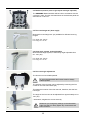
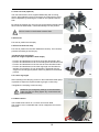
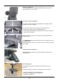
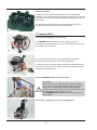
1
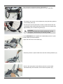
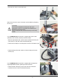
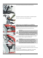
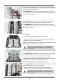
SWINGBO Plus
System - Wheelchair
for kids & adolescents
User manual
- Partnering together to mobilise kids
User manual SWINGBO Plus System-wheelchair for kids & adolescents
Content:
Page
1
Common Information
1.1
Preface _______________________________________________________________________________________2
1.2
Application ____________________________________________________________________________________2
1.3
Declaration of conformity _________________________________________________________________________2
1.4
Terms of warranty _______________________________________________________________________________2
1.5
Servicing and repairs ____________________________________________________________________________2
2
Sicherheitshinweise __________________________________________________________________________________3
2.1
Meaning of symbols _____________________________________________________________________________3
2.2
Common safety instructions _______________________________________________________________________3
3
Delivery and Preparing for use _________________________________________________________________________6
4
Adjusting and adaptation possibilities _________________________________________________________________10
4.1
Wheel lock (knee lever wheel locks, mounted on the frame) _____________________________________________10
4.2
Wheel lock (wheel lock lever integrated in wheel guards) _______________________________________________ 11
4.3
Seat width / seat height / camber __________________________________________________________________ 11
4.4
Seat depth ___________________________________________________________________________________12
4.5
Backrest height (backrest panel trough shaped and height adjustable)_____________________________________12
4.6
Backrest (backrest panel angle- and height adjustable) ________________________________________________12
4.7
Recline (backrest panel trough shaped and height adjustable) ___________________________________________13
4.8
Recline (backrest panel angle- and height adjustable) _________________________________________________13
4.9
Active degree _________________________________________________________________________________13
4.10 Tilt __________________________________________________________________________________________13
4.11
Height adjustment of push-bar ___________________________________________________________________14
4.12 Height- and angle adjustment of push-handle ________________________________________________________14
4.13 Anti tip ______________________________________________________________________________________14
4.14
Detaching rear wheels with quickrelease ___________________________________________________________15
4.15 Pneumatic tyres / PU-tyres ___________________________________________________ ___________________15
4.16 Hand rims_________________________________________________________________ ___________________15
4.17 Drum brakes __________________________________________________________________________________16
5
Accessories _______________________________________________________________________________________17
5.1
Seat panel ___________________________________________________________________________________17
5.2
Backrest (backrest panel angle- and height adjustable) ________________________________________________17
5.3
Backrest (backrest panel trough shaped and height adjustable) __________________________________________18
5.4
Foot rest hanger 90° (knee angle) _________________________________________________________________18
5.5
Knee angle system (angle adjustable) ______________________________________________________________18
5.6
Footrest angle adjustment _______________________________________________________________________18
5.7
Footrest lock (optional) _________________________________________________________________________19
5.8
Footrest _____________________________________________________________________________________19
5.9
Footrest with heel stop __________________________________________________________________________19
5.10 Single foot rest hanger (with two single footplates in boat shape) _________________________________________19
5.11
Lower leg length _______________________________________________________________________________19
5.12 Seat cushion__________________________________________________________________________________19
5.13 Backrest cushion ______________________________________________________________________________20
5.14 Spoke guards _________________________________________________________________________________20
5.15 Anti tip ______________________________________________________________________________________20
5.16 Tip assist ____________________________________________________________________________________21
5.17 Headrest „standard“: with cushion ________________________________________________________________21
5.18
Headrest bracket „universal“ _____________________________________________________________________21
5.19
Headrest with occiput upholstery _________________________________________________________________21
5.20 Trunk supports _______________________________________________________________________________ 22
5.21 Chest-/thoracic support ________________________________________________________________________ 22
5.22 Armrests with PU pads ________________________________________________________________________ 22
5.23 Therapy tray _________________________________________________________________________________ 22
5.24 Lap belt _____________________________________________________________________________________23
5.25 4-point lap belt ________________________________________________________________________________23
5.26 Ankle hugger _________________________________________________________________________________24
6
Transport __________________________________________________________________________________________24
6.1
In the trunk (luggage space) of a car _______________________________________________________________24
6.2
Using SWINGBO Plus for bus transport ____________________________________________________________24
6.3
Transfer - getting into or out of the wheelchair _______________________________________________________25
7
Maintenance _______________________________________________________________________________________26
8
Technical Data _____________________________________________________________________________________27
1
1. Common Information
1.1 Preface
Thank you for selecting the SWINGBO Plus wheelchair. We have designed this high-quality product to make
your life safer and easier, and we’ve included this manual to help you use and care for it. Please read the following instructions to make sure you use this product as recommended. If you have any further questions, or if
you have any problems, please contact your healthcare provider.
We hope that SWINGBO Plus meets your expectations.
The design, as described in these instructions for use, are subject to technical alterations without notice.
1.2 Application
The SWINGBO Plus wheelchair is designed solely for individual indoor and outdoor use by persons who are
unable to walk or who have a walking impediment, and can be operated by the patient or by another person.
Assistance may be required due to:
• Paralysis (paraplegia / tetraplegia or tetraparesis)
• Muscle and nerve disorders
• Loss of limbs (dysmelia/lower limb amputation)
• Imperfect osteogenesis
• Infantile/spastic cerebral palsy
• Poliomyelitis
• Spina Bifida
1.3 Declaration of Conformity
HOGGI® GmbH as manufacturer with sole responsibility declares that the SWINGBO Plus conforms to the
requirements of the 93/42/EEC Guidelines.
1.4 Terms of Warranty
Warranty applies only when the product is used according to the specified conditions and for the intended
purposes, following all manufacturer’s recommendations.
The manufacturer is not responsible for damages caused by components and spare parts not approved by
the manufacturer.
1.5 Service and Repairs
Service and repairs on the SWINGBO Plus should only be carried out by authorized HOGGI dealers. Should
any problems arise, please contact the dealer who supplied your SWINGBO Plus.
Authorized dealers only fit original HOGGI spare parts.
For Preparing, repair and service, the following tools are required:
Allen wrench, size: 3 mm, 4 mm, 5 mm und 6 mm
Screw wrench, size: 8 mm, 10 mm, 13 mm, 17 mm, 19 mm and 24 mm
Your authorized HOGGI dealer:
2
2
2.1
Safety instructions
Meaning of symbols
Caution!
Warning of possible danger of accident and injury. Warning of possible technical damage.
Information!
about use of product.
Information!
for service-personnel.
Attention!
Read manual before!
2.2
Common safety instructions
Read manual completely before use!
Familiarize yourself with handling and functions of the wheelchair before use and practice
the handling.
You are responsible for the safety of your child. The safety of your child could be
affected if you do not follow the instructions of this manual. Nevertheless not all possible
circumstances and unpredictable situations can be covered by this manual. Reason, care
and circumspection are not features of the product, they are required of persons, who use
the wheelchair or attend it. The person, who is using the wheelchair and its accessories
should understand all instructions. It must explained to every other person using the
wheelchair and its accessories.
If instructions are not clear and further explanations become necessary, or if you have
further questions please contact your HOGGI dealer.
Practise with the new wheelchair on even, straightforward terrain first, together with the
child. Together with the child, learn how the wheelchair reacts when the centre of gravity
shifts; for example on slopes or inclines or when clearing obstacles such as steps and
curbs. This should be done only with assistance from another person.
Using an anti-tip is strongly recommended for inexperienced wheelchair users.
Strap in your child at all times, when in the wheelchair.
HOGGI points out, that any use beside the typical use can be dangerous. The wheelchair
is not suitable for jogging, running, skating or similar activities. Swivelling front wheels tend
to wobble at higher speed, which can cause a sudden stop and tip over of the wheelchair.
Use the wheelchair only at regular walking speed. Under no circumstances leave the
handle bar while pushing and never push the wheelchair away.
The wheel chair should only be used on solid level ground.
Use your wheelchair as intended by the manufacturer. For instance, do not drive into
obstacles (including steps, curbs) without braking. Do not „jump” the chair down from
higher surfaces.
3
To clear obstacles such as steps and curbs, tilt the wheelchair onto the rear wheels (pull it
backwards to go up; to descend, slowly lower it forward).
If only one attendant is available when ascending or descending stairs, an incorrectly set
anti-tip (if mounted at all) can lead to severe falls. Adjust the anti-tipper so that it does not
come in the way of the steps during transport. Afterwards, swing the anti-tipper back to its
operational position.
Do not go up or down stairs without the assistance of another person. If devices such
as ramps or elevators are available, please use them. Ensure that the anti-tip (if mounted)
is outside the danger-area. If wheelchairfriendly access is missing, two attendants must
carry the wheelchair over the obstacle.
When ascending slopes or ramps and when crossing obstacles on upward slopes, always
lean the wheelchair user‘s upper body far forward.
When descending slopes, do not drive without braking and reduce your speed. Reduced
load on the casters due to centre of gravity shifting can cause the casters to flutter.
If you have to park on a slope, face the wheelchair uphill with the brakes engaged and
ensure that the seat is in the upright position. There is a risk that the pushchair might tip
over backwards if the seat is the reclined position.
Before leaving the wheelchair and before getting into and out of it, always lock the wheel
locks.
It is only allowed for children with a body weight less than 20 kg to stand on the footplate
getting into the wheelchair.
For children above 20 kg fold up the footplate before getting into or out of the wheelchair.
Depending on footplate settings and wheelchair geometry, the wheelchair may tip over if
the user boards the chair using the footplate. First practise boarding the chair with the child
and an attendant who can secure the wheelchair, and modify footplate and seat height
settings if the chair has a tendency to tip over. In addition, turn the caster fork to the front
prior to using the footplate for getting into the wheelchair; this increases the wheelbase
and thereby the wheelchair‘s stability against tipping.
The effectiveness of the wheel lock and the overall driving quality are dependent on
adequate air pressure. With properly inflated rear wheels and even tyre pressure on both
sides, your wheelchair is much easier to operate and manoeuvre. Before starting to use
your wheelchair, check that the tyres are inflated correctly. The required air pressure is
printed on the side of the tyre. For rear wheels, it should be at least 6 bar.
All brakes acting on the tyres do not serve as service brake but are only designed as
parking brake (wheel lock). The wheel locks must not be used as driving brakes for slowing
down the wheelchair, as in extreme cases, the abrupt stopping of the wheelchair can lead
to falls.
Please keep packaging material away from children. Plastic packaging presents the
danger of suffocation.
Disposal of waste: The packaging material as far as metal, aluminium and plastic parts can
be recycled. The recycling must be operated according to the national and legal terms.
Never leave your child unattended in the wheelchair even when they are strapped in and
the brakes engaged.
In the dark, the user should wear light clothing or clothing with reflectors in order to improve
visibility. Ensure that the reflectors installed on the sides and rear of the wheelchair are
easily visible. We also recommend installing active illumination.
4
Extreme settings (e.g. shortest wheelbase and seat in the backmost position) combined
with an unfavourable body posture can cause the wheelchair to tip even on level ground.
Static stability is >10,5° inclination.
Attaching heavy bags or other weight to the push handles can adversely affect stability.
Under no conditions should the anti-tip(s) assume the function of transport wheels, for
example to transport a person in the wheelchair with the rear wheels removed. The antitipper must audibly lock in place, before it is able to bear loads.
Firm seating must be verified by the user or by an attendant.
The SWINGBO Plus is only intended to carry one child at a time.
The maximum load for the SWINGBO Plus is 75 kg.
Accessories and add-ons reduce the maximum load proportionately.
Caution!
We recommend that, wherever and whenever possible, users transfer to the seats installed
in the motor vehicle and use the corresponding vehicle restraint systems, because this is
the only way to ensure optimum protection of the passengers in case of an accident.
Your SWINGBO Plus wheelchair is permitted for use as a seat in a motor vehicle.
Be careful in case of extreme temperatures. The wheelchair can heat up significantly when
in the sun or in the sauna. In extreme cold, there is a risk of hypothermia.
Slowing down from high speeds or when descending longer slopes tends to heat up the
hands and fingers, especially if using aluminium push rings. When using the wheelchair
outdoors, leather gloves should be worn. Gloves provide the wheelchair user with a better
grip and protect his or her fingers from dirt and hot metal.
Always make sure that the quick-release axles are correctly set on the rear wheel. It must
not be possible to remove the rear wheel unless the button on the quick-release axle is
pushed
The assembly of a seat shell is only permitted within the specified seating area.
The manufacturer of that new product combination has to test the stability and the adherence of the maximum load before commissioning.
Whenever you change any settings on the wheelchair, make sure that you firmly tighten
any screws that have been loosened.
Adjustments with a high active degree demand a practised driver and the use of an anti tip.
Don´t use the footrest to get into and out of the wheelchair.
Neither seat nor backrest height may be exceeded.
5
3 Delivery and preparing for use
1
Your SWINGBO Plus wheelchair will normally be supplied
completely mounted with detached or folded push-bar / push-handle
and with removed front castors and rear wheels. (1).
The original package contains the following parts:
• Wheel chair with detached or folded push-bar / push-handle
• Rear wheels and quick-release axles unmounted
• Front castors already mounted in the front castor forks
• Additional accessories as ordered
• Instructions and list of tools required
Please remove the transport packaging carefully.
To prepare the wheelchair for use please proceed as follows:
• Grip the head of the quick-release axle as illustrated (2) and press
the release knob.
2
3
• Whilst pressing the release knob, position the quick-release axle
into the rear wheel bearing (3).
• Place the wheelchair onto the front castors and lift the wheelchair
by holding the rear of the seat (4).
• nsert the rear wheel and the quick-release axle into the axle
housing. Hold the spokes (4) close to the wheel hub and press the
release knob with your thumb. The rear wheel can then be easily
slid into position.
• Ensure that the quick-release axle is securely fixed in the axle
housing.
CAUTION!
Push each rear wheel to check that each quick-release
axle is safely located.
4
If your SWINGBO Plus is supplied with a foldable backrest it is
possible that it is folded for the transport.
• Pull the backrest at the cross tube into the upstanding position (5).
Whenever you change any settings on the wheelchair,
make sure that you firmly tighten any screws that have
been loosened.
5
6
If your SWINGBO Plus is supplied with an angle- and height
adjustable backrest it is possible that it is in hinged position for the
transport.
• Pull the backrest as shown to the back (6).
6
• Pull the bowden cable as shown (7).
• Let the bolt lock in place in the desired backrest angle position.
CAUTION!
Check with a sharp push on the backrest that the bolt is
securely located.
7
If your SWINGBO Plus is supplied with an anti tip it is directed to the
front. That is the non-active position. (8).
8
The SWINGBO Plus wheelchair can be supplied with one or with
two anti tippers.
Illustration 9 shows an anti tip in the „active position“.
9
• To adjust the „active position“ push the anti-tip with your foot to
the bottom (10).
10
7
Turn the anti-tip to the left as shown in illustration 11.
(if the anti-tip is mounted on the left side turn it to the right side).
11
• The length of the anti-tip can be adjusted by using the three positions
on its locating tube (12).
• The anti-tip should be positioned so that the small wheel at the end
of anti-tipper tube projects beyond the radius of the rear wheels and
approximately 2-3 cm above the ground (12).
12
CAUTION!
By tipping the wheelchair carefully backwards onto the
anti-tippers, check that they are securely located.
If your SWINGBO Plus is supplied with a detachable push-bar / pushhandle, please proceed as follows:
• Open the cam lever on both sides (13).
13
• Place the push bar / push-handle down into their locating brackets (14).
14
• Press in the spring button and slide the push bar / push-handle
downwards fully into its bracket, until it clicks into position (15).
15
8
• Close the cam lever on both sides (16).
16
When the cam lever is open, its tension can be altered by adjusting
the nut (17).
CAUTION!
The maximum adjustment of the push bar is predetermined. Under no circumstances should they be
adjusted beyond these limits.
Press on the push bar to ensure that they are securely
located.
17
If your SWINGBO Plus wheelchair is supplied with seat or back
upholstery from HOGGI, please proceed as follows:
• Slide the upholstered seat cushion under the backrest and lay the
seat cushion on the seat surface as illustrated (18).
• Fasten the front flaps on the seat panel as shown in illustration (18).
18
• Fasten the flap of the seat cushion to the back edge of the seat
surface (19).
19
If your SWINGBO Plus wheelchair is supplied with an angle and
height adjustable backrest, please proceed as follows:
• Fasten the side cushioning on the inner side of the backrest.
It should cover the contour of the backrest (20).
20
9
• Fix the side cushioning also with the press button (21).
21
• Pull the back cushion from top to bottom on the backrest panel.
• Press the cushion firmly on the backrest panel.
22
4 Adjusting and adaptation possibilities
4.1 Wheel lock (knee lever wheel locks, mounted on the frame)
• Press the brake lever below to lock the wheel lock (23).
23
CAUTION!
All brakes acting on the tires do not serve as a slow down
brake but are only designed as a parking brake (wheel
lock). The wheel locks must not be used as driving brakes
for slowing down the wheelchair, as in extreme cases, the
abrupt stopping of the wheelchair can lead to falls.
The brake shoe presses on the tires and grips it tightly. The brake
shoe is, therefore, at a 90° angle to its holder (24).
24
B
CAUTION!
The effectiveness of the wheel lock are dependent
on adequate air pressure. Before starting to use your
wheelchair, check that the tires are inflated correctly.
The required air pressure is printed on the side of the
tires. For rear wheels, it should be at least 6 bar.
• To release the wheel lock pull the brake lever upwards (25).
When the brakes are released the brake shoe should be 10 mm from
the wheel (25 A).
This distance can be adjusted by the adjustment screw (25 B).
The wheel locks should only be adjusted by a technician.
A
25
10
4.2 Wheel lock (wheel lock lever integrated in wheel guards)
Press the brake lever below to lock the wheel lock (26).
CAUTION!
All brakes acting on the tires do not serve as a slow down
brake but are only designed as a parking brake (wheel
lock). The wheel locks must not be used as driving brakes
for slowing down the wheelchair, as in extreme cases, the
abrupt stopping of the wheelchair can lead to falls.
26
The brake shoe presses on the tires and grips it tightly.
The brake shoe is, therefore, at a 90° angle to its holder (27).
CAUTION!
The effectiveness of the wheel lock are dependent
on adequate air pressure. Before starting to use your
wheelchair, check that the tires are inflated correctly. The
required air pressure is printed on the side of the tires. For
rear wheels, it should be at least 6 bar.
A
27
• To release the wheel lock pull the brake lever upwards as shown
(28).
28
When the wheel lock is released the brake shoe should be 12-15 mm
from the wheel (29 A).
B
This distance can be adjusted by the adjustment screw (29 B) or by
displacing the wheel lock on the mounting clamp (27 A).
The wheel locks should only be adjusted by a technician.
29
4.3 Seat width / Seat height / Camber
SWINGBO Plus is available in four seat widths (28, 32, 36, 40 cm).
The seat width gets measured between the wheel guards and it depends on the cross tubes (30).
The SWINGBO Plus wheelchair will be built in accordance with
the customer’s order. It is possible for the technician to modify the
wheelchair with a different seat width.
11
30
A
The seat height is dependent on the chosen rear wheels and front castors, as well as on the height of the rear axle and the position of the front
castors in the front castor forks (31).
The SWINGBO Plus wheelchair will be built in accordance with the
customer’s order. It is possible for the technician to modify the wheelchair
with a different seat height.
31
The SWINGBO PLUS wheelchair can be supplied with rear wheels
inclined (camber) 6° (32 left) or 9° (32 right) from the vertical.
The SWINGBO Plus wheelchair will be built in accordance with the
customer’s order. It is possible for the technician to modify the wheelchair
with a different camber.
32
4.4 Seat depth
• To adjust the seat depth remove the seat cushion first.
• Loosen the four screws under the seat and adjust the seat depth by
sliding the seat to the required position.
To get the maximum stability the four screws should be positioned with a
distance (to each other) as far as possible.
33
Whenever you change any settings on the wheelchair,
make sure that you firmly tighten any screws that have
been loosened.
4.5 Backrest height (backrest panel trough shaped and height adjustable)
If your SWINGBO Plus wheelchair is supplied with a trough shaped, 2parts, height adjustable backrest, please proceed as follows:
34
• To adjust the seat depth remove the backrest cushion first.
• Loosen the four screws on the backrest panel and adjust the backrest
height by sliding the panel to the required position (34).
4.6 Backrest height (angle- and height adjustable)
If your SWINGBO Plus wheelchair is supplied with an angle- and height
adjustable backrest please proceed as follows:
• Loosen the four screws on the backrest panel and adjust the
backrest height by sliding the panel to the required position (35).
Whenever you change any settings on the wheelchair,
make sure that you firmly tighten any screws that have
been loosened.
35
12
4.7 Recline (trough shaped backrest)
• Remove the rear wheel and the wheel guard as described under
„3 Delivery and preparing for use“.
.
• Loose and remove both hexagon socket screws.
• Repeat that on the opposite side too
• Tilt the backrest and choose one of the five backrest angles (see
marking).
• Tighten all fasteners firmly.
36
4.8 Recline (angle- and height adjustable backrest)
• Hold with one hand the upper edge of the backrest panel as
shown.
• Pull the bowden cable until the bolts are completely withdrawn into
its housing.
• Now one of the five backrest angles can be chosen.
• Release the bolt to lock into the required position.
CAUTION!
Check with a sharp push on the backrest to ensure that
the bolt is securely located.
37
4.9 Active degree
The active degree describes the relation of the backrest position
to the rear wheels. The more the backrest is positioned to the rear
of the axle, the more active the SWINGBO PLUS can be driven.
(e.g. lifting of the front wheels). That means contrary a safer driving
position if the adjustment is set above or in front of the rear axle.
The active degree is adjustable in 6 steps (0-5) by sliding the axle
unit (38).
38
CAUTION!
Adjustments with a high active degree demand a
practised driver and the use of an anti tip.
The SWINGBO Plus will be built in accordance with the
customer’s order. It is possible for the dealer to modify the
active degree.
4.10 Tilt
• Lock both wheel locks.
• Pull the release handle (39) until the locking mechanism is fully
disengaged.
39
By using the push-bar or push-handles, the seat unit can be adjusted
to any angle between -7° and +45°. Set the required seat angle and
allow the bolt to lock in the required position.
CAUTION!
Push sharply on the push-bar or push-handle to ensure
that the bolt is securely located.
40
13
4.11 Height adjustment of the push-bar
The ratchet joint on the push-bar allows them to be adjusted to a
comfortable height for the attendant.
By pressing in the knobs on both ratchet joints (41), the push bar can
be turned to the required position.
41
If your SWINGBO Plus wheelchair is supplied with a detachable pushbar it is possible to adjust the height of the push-bar after loosening the
cam levers (42).
But it is advisable to adjust the height about max. 5 cm, otherwise the
tilt function can be limited.
42
4.12 Height adjustment of the push-handles
The push-handles are height and angle adjustable.
43
4.13 Anti tip
• The angle of the anti tip can be adjusted by loosening the screw (44).
44
• To achieve more free space for the feet it is possible to turn the
anti tip outwards (45).
45
14
4.14 Detaching the rear wheels with quick-release axles
The rear wheels are removed by means of a quick-release
mechanism. This reduces the volume of the wheelchair for
transportation:
• Tilt the wheelchair onto the front castors and lift it by holding the
rear edge of the seat.
• Grip the spokes close to the wheel hub and, with the thumb, press
the release knob of the quick- release axle.
• Pull the rear wheel with the quick-release axle out of the axle
housing.
• To avoid a risk of snagging, it may be preferable to withdraw the
quick-release axles from the rear wheels.
• To re-assemble the rear wheels refer to section 3 “Delivery and
preparing for use”.
CAUTION!
Push sharply on each rear wheel to ensure that the quickrelease axles are securely located.
46
47
4.15 Pneumatic tires / PU-tires
The rear wheels can be supplied with pneumatic tires (49, left).
The car type valves enable the tyres to be checked or inflated at any
petrol station or by means of a suitable pump, supplying a minimum
6 bar pressure.
Check the maximum tire pressure, which is indicated on the tire.
48
The drive wheels can also be supplied with solid PU-tyres (49, right).
49
4.16 Hand rims
Hand rims can be supplied in aluminium (50) or stainless steel (51)
according to preference.
50
15
• Stainless steel hand rim (51).
51
Hand rims can be supplied with a standard diameter (52, left) or with
a larger diameter (52, right). These are called respectively hand rims
“standard” or hand rims “high”.
The SWINGBO Plus wheelchair will be built in accordance with the
customer’s order. It is possible for the retailer to fit alternative push
rims.
52
All hand rims can be mounted close to the rear wheel or a little
further apart. A future modification is possible again.
53
4.17 Drum brakes
In addition to wheel lock and wheel lock (lever integrated in wheel
guards), the SWINGBO Plus wheelchair can be fitted with drum
brakes.
The drum brakes are activated from the push-bar or push-handles.
54
Each drum brake is operated by a brake lever.
55
16
• To apply the drum brake squeeze the brake lever (56).
• With the finger tips press the rocking catch, until it locks with a click
and release the brake handle.
When the brake lever is squeezed again, the rocking catch is
unlocked and the drum brake can be released.
56
The brake force can be adjusted by the adjustment screw.
57
5 Accessories
All accessories not installed by the manufacturer must be installed by trained technicians.
The following notes on installation are for your information but should be performed by trained technicians.
Straps on accessories are usually extra long to accommodate every option.
Shorten excess strap ends on accessories so that they can not be trapped.
To prevent strap ends from fraying the cut ends can be melted together with a flame (eg. lighter).
5.1 Seat panel
The SWINGBO Plus wheelchair will be built in accordance with the
customer’s order.
Function and adjustment of the seat panel are described in 4.3 and
4.4.
58
5.2 Backrest (angle- and height adjustable)
The SWINGBO Plus wheelchair will be built in accordance with the
customer’s order.
Function and attachment of the backrest panels are described in 4.6
and 4.8.
59
17
5.3 Backrest (backrest panel trough shaped and height adjustable)
The SWINGBO Plus wheelchair will be built in accordance with the
customer’s order. Function and attachment of the backrest panel are
described in 4.5 and 4.7.
60
5.4 Foot rest hanger 90° (knee angle)
Mounted foot rest hanger 90° (61) available for different lower leg
lengths:
LLL short: 20 - 36 cm
LLL long: 20 - 41 cm
61
5.5 Knee angle system, angle adjustable
Mounted knee angle system, continuously angle adjustable from
85 - 160° (62).
LLL short: 20 - 36 cm
LLL long: 20 - 41 cm
62
5.6 Foot rest angle adjustment
The foot rest can be folded upwards.
To get in the wheelchair the footrest must be always
folded upwards.
63
The position of the foot rest can be adjusted by loosening the four
screws on the foot rest bracket (63).
This alters the location of the foot rest and, therefore, also the foot
rest angle.
The angle of the foot rest can be adjusted from approximately 80° to
100° (64).
• Afterwards, retighten the screws securely.
64
Whenever you change any settings on the wheelchair,
make sure that you firmly tighten any screws that have
been loosened.
18
5.7 Foot rest lock (optional)
The foot rest bracket can be supplied additionally with a locking
device. When adjusting the foot rest angle, the locking device must
also be adjusted, by loosening the screws on the right and the left
side.
By pulling the release ring, the foot rest can be folded upwards. When
the foot rest is folded down, it will automatically lock into position.
65
All four screws on the footrest must be fixed.
5.8 Foot rest
66
Foot rest to position the feet (66).
5.9 Foot rest with heel stop
Foot rest to position the feet with additional heel stop. The heel stop
prevents the sliding of the feet (67).
67
5.10 Single foot rest hanger
(with two single footplates in boat shape)
• Function and attachment of the knee angle are described in 5.5.
• Function and attachment of der foot rest angle are described in 5.6.
• Function and attachment of the foot rest lock are described in 5.7.
• Function and attachment of the lower leg length are described in
5.11 but it is necessary (if your wheelchair is equipped with the
single foot rest hanger) to position both foot plates into the desired
position.
5.11 Lower leg length
68
After releasing both clamping screws on the footboard bracket (69) it
is possible to adjust the required lower leg length continuously:
• Retighten the clamping screws securely.
Whenever you change any settings on the wheelchair,
make sure that you firmly tighten any screws that have
been loosened.
69
5.12 Seat cushion
The HOGGI seat cushion is 3 cm thick and is foam filled.
The cushion cover is washable and can be unzipped to remove the
foam pad.
70
19
5.13 Backrest cushion
The HOGGI back cushion is 2,5 cm thick and is foam filled.
The cushion cover is washable and can be unzipped to remove the
foam pad (71).
The side pads also belong to the backrest cushion (only for the
angle- and height adjustable backrest). See close up picture.
71
In order to adjust the height of the backrest the back cushion and
side pads must be removed first.
5.14 Spoke guards
The spoke guards prevent the child’s fingers from being trapped in
the spokes.
The transparent spoke guards can be painted by the child or have
decorative stickers applied. (72).
72
5.15 Anti tip
The SWINGBO Plus wheelchair can be supplied with one or two
anti tip units. The anti tip increases the stability of the wheelchair.
The function and attachment of the anti-tips are described in the
section “Delivery and preparing for use“ and in 4.13.
73
74
CAUTION!
If only one attendant is available when ascending or
descending stairs, an incorrectly set anti-tipper
(if mounted at all) can lead to severe falls.
Adjust the anti tip so that it does not come in the way of
the steps during transport. Afterwards, swing the anti tip
back to its operational position.
75
20
5.16 Tip assist
The tip assist conduces to tip the wheelchair and helps the attendant
consequently crossing kerbs and stairs (76).
76
5.17 Headrest standard with cushion
This headrest is only lightly contoured and serves as a contact
surface for the back of the head.
This headrest can be mounted on both backrests (77).
77
After loosening the four screws the headrest can be adjusted in the
height (78).
The cover can be removed for cleaning.
Whenever you change any settings on the wheelchair,
make sure that you firmly tighten any screws that have
been loosened.
78
5.18 Universal headrest bracket
The bracket for the headrest can be mounted on both backrests (79).
Release the clamping lever to adjust the height of the headrest.
Whenever you change any settings on the wheelchair,
make sure that you firmly tighten any screws that have
been loosened.
79
5.19 Headrest with occiput upholstery
This headrest can be adjusted both in height and in angle.
The metal frame under the upholstery can be supplied to suit
head size.
The cover can be removed for cleaning.
80
21
5.20 Trunk supports
The trunk supports are separately adjustable and the size of the
pads is approx. 33 - 43 cm (81).
81
A
82
B
A
5.21 Chest-/ thoracic support
The chest-/ thoracic support are adjustable in the height and the
breadth as well as in 2 angles.
B
• To open the chest-/ thoracic support use the connectors.
• Press the connectors at the marked position (A).
• At the marked buckles (B) it is possible to fix or rather loosen the
chest-/ thoracic support.
Illustration 83 shows the chest-/ thoracic support adjusted in two
different angles.
The SWINGBO Plus wheelchair will be built in accordance with the
customer’s order.
It is possible for the retailer to convert the chest-/ thoracic support to
other angles.
83
5.22 Armrests with PU-pads
After loosening the marked screws the height of the armrests is
adjustable (84).
84
5.23 Therapy tray
The therapy tray can be mounted with terminal strips on the
armrests.
The terminal strips are preset to the distance of the armrests.
85
• Loose the knurled nut and press the clamp.
• Position the therapy tray on the armrests.
• Tighten the knurled nut.
22
5.24 Lap belt
At the end of the belt are pre-assembled buckles.
• Lead the end of the lap belt as shown, so that the belt passes only
once through the buckle.
The length of the free belt end causes the lap belt length.
• Lead the belt end through the slotted holes on the left and right
side of the backrest base (86).
86
• Lead the free belt end trough the buckle once again (87).
87
Open the lap belt by pressing the red button (88).
When the lap belt is fastened, fine adjustment can be made by
pulling one free end of the belt.
88
5.25 4-point-harness
The 4-point harness should be installed by authorized dealers or
trained technicians.
Take off the seat upholstery first and mount the buckles at the
slotted holes.
The lap belt ends and the tension belts get mounted and preset as
described in 5.24.
89
Open the lap belt by pressing the connectors.
At the belt buckle the lap belt can be readjusted by adducting the
lap ends (fine tuning).
90
23
5.26 Ankle hugger
By using the ankle straps feet and ankles can be comfortably
positioned. The ankle straps are passed through the rings on the foot
rest. This holds the heels against the raised heel plate at the rear of
the footrest.
The ankle straps can be adjusted and then fastened with Velcro.
The fastening should always be on the outside (91).
91
6 Transportation
6.1 In the trunk (luggage space) of a car
The SWINGBO Plus wheelchair can according to size and
specification, be transported as one unit, with folded down backrest
and folded up foot rest. (92).
92
For convenience of handling it may be preferable to partially
dismantle the wheelchair into a few main components.
To achieve the most compact folding package fold the backrest and
foot rest but remove the rear wheels, the anti tip assemblies and the
push bar/ push handles (93).
93
6.2 Using SWINGBO Plus for bus transport
94
CAUTION!
We recommend that, wherever and whenever possible,
users transfer to the seats installed in the motor vehicle
and use the corresponding vehicle restraint systems,
because this is the only way to ensure optimum protection
of the passengers in case of an accident.
Your SWINGBO Plus is admitted for use as a seat in a
motor vehicle.
6.3 Transfer - getting into or out of the wheelchair
95
24
CAUTION!
• Always lock the wheel locks before getting into or out of
the wheelchair.
• First practise boarding the chair with the child and an
attendant who can secure the wheelchair, and modify
footplate and seat height settings if the chair has a
tendency to tip over.
96
For adolescents it can be advantageous, according to age, weight
and ability, to make a transfer over the side of the wheelchair.
Firstly position the wheelchair at an angle of 45° to the seat or
wheelchair (96), from which a transfer is to be made.
Apply the parking brake (97).
During the transfer the seat surface, the backrest surface, the push
rims or briefly the side of the seat can be used for support.
97
The transfer should be practiced with a helper, until it can be accomplished safely. The transfer should be carried out in one movement.
Afterwards, fold down the foot rest and position the feet on it. If necessary correct the seat position.
Finally the parking brake can be released and the wheelchair is ready
for use.
Carry out the sequence in reverse when getting out of the wheelchair.
98
25
7 Maintenance
Your SWINGBO Plus wheelchair is CE approved. The manufacturer herewith guarantees that this medical
product as a whole conforms to the requirements of 93/42/EEC guideline.
The proper function of the wheelchair, especially of the wheel locks, should be checked before every use.
Safety nuts should be used only once. If they have been loosened several times, they must be replaced.
The items listed in the following table must be checked by the user at the indicated intervals. Failure to carry
out these simple checks may lead to problems arising that could invalidate the warranty.
Checkdaily before useweekly monthly
Function test of the brake/wheel lock
X
Function test of the anti tip
X
Function of rear wheels quick-release system
X
Check stability of footplateX
Air pressure (see indication on tyre)
X
Push rims for damageX
Screw connectionsX
Visual inspection for worn parts (e.g. tyres, bearings)
X
Dirt on bearingsX
Spoke tension of the rear wheelssX
Function test of the tilt mechanismX
Should any defects become obvious, please contact your authorized HOGGI dealer to eliminate them. We also
recommend that you have your SWINGBO Plus serviced by your technician every twelve months.
Instructions for cleaning and maintenance
- Clean all frame components and plastic parts using mild detergents only. (e.g. Sagrotan)
- Padding parts can be washed at 40 °C. If washed in a washing machine, put them in a
linen bag or a pillow case.
- In most cases, wiping with a damp cloth is sufficient..
- Do not use your SWINGBO Plus wheelchair in salt water.
- Keep sand or other particles from damaging the wheel bearings.
- If your wheelchair gets wet, towel-dry it as soon as possible.
- Hair and dirt particles generally accumulate between the caster wheel and fork. This can
restrict the caster wheels from rotating smoothly. Remove the caster and thoroughly clean
the fork and caster using a mild detergent.
- The rear wheels feature a quick-release system. To keep this system operational, ensure
that no dirt adheres to the quick-release axle or axle housing. The quick-release axle
should also be lightly lubricated regularly with resin-free sewing machine oil.
- Screw connections should be checked frequently, in particular when beginning to use the
wheelchair and after any adjustment. If a screw connection becomes loose repeatedly,
consult your dealer.
26
8 Technical data
Dimensions (cm) and weights (kg)
Seat width
28
32
36
40
Seat depth
30 - 38
30 - 42
34 - 46
38 - 50
Backrest height
38 - 47
42 - 51
46 - 55
50 - 59
Seat angle
-7° bis + 45° (adjustable in 4° steps)
Backrest angle
Backrest angle- and height
adjustable
Backrest trough shaped
adjustable in 10° steps from 75° - 115° or from 80° - 120°
adjustable in 5° steps from 85° - 105°
Lower leg length
20 cm - 41 cm
Footrest angle
-10° to + 10°
Seat height
41 cm - 51 cm
Rear wheel
diameter
20“, 22“, 24“
Front castor
diameter
100 mm (4“), 125 mm (5“), 140 mm (5,5“)
Camber
6° or 9°
Weight
SWINGBO Plus in SW32, 24“ rear wheels, 140 mm rubber tires, pushbar, foldable, seat panel, backrest panel trough shaped and height adjustable, knee angle system, footrest with heel stop, anti tip and tip assist =
20 kg
Load capacity
75 kg
Turning diameter
max. 148 cm
Attention!
Accessories and add-ons reduce the maximum load proportionately.
27
Your notes:
Your notes:
Your notes:
HOGGI GmbH
Eulerstraße 27
D - 56235 Ransbach-Baumbach
Fon: (+49) 26 23 / 92 499-0 · Fax: (+49) 26 23 / 92 499-99
e-mail: [email protected] · Internet: www.hoggi.de
© HOGGI GmbH 1910-0029-GB_01-2013
Manufacturer: