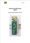
Download User Manual ARM-S - Sports Timing Systems
Transcript
ARMS_USERGUIDE3-6
Dec06
User Manual
ARM-S
Advanced Radio Modem
-1-
®
ARMS_USERGUIDE3-6
Dec06
Summary
1
PRESENTATION.................................................................................................................................................... 4
1.1
1.2
1.3
1.4
2
INTRODUCTION .................................................................................................................................................. 4
GENERALITIES ..................................................................................................................................................... 4
AVAILABLE VERSIONS.......................................................................................................................................... 4
OPERATING PRINCIPLE ........................................................................................................................................ 5
INSTALLATION ..................................................................................................................................................... 5
2.1
ANTENNA ........................................................................................................................................................... 6
2.1.1
Electrical case or cabinet mounting............................................................................................... 7
2.1.2
Outdoor pole mounting...................................................................................................................... 7
2.1.3
Spectrum coverage ............................................................................................................................. 8
2.1.4
Transmission range ............................................................................................................................ 8
2.1.5
Channel selection................................................................................................................................. 8
2.2
RADIO MODEM CONNECTIONS ........................................................................................................................... 9
2.2.1
Power supply......................................................................................................................................... 9
2.2.2
Serial RS232.......................................................................................................................................... 9
2.2.3
Serial RS485........................................................................................................................................ 10
2.2.4
Digital input and output .................................................................................................................. 10
3
CONFIGURATION............................................................................................................................................... 11
3.1
3.2
3.3
4
OPERATING MODE............................................................................................................................................ 12
4.1
4.2
4.3
4.4
4.5
5
RADIO MODEM CONFIGURATION...................................................................................................................... 11
CONFIGURATION WITH WINDOWS-BASED UTILITY « ARM-MANAGER » ...................................................... 11
CONFIGURATION USING HAYES COMMANDS (AT)........................................................................................... 11
TRANSPARENT MODE ....................................................................................................................................... 12
SECURIZED MODE ............................................................................................................................................. 14
MODBUS MODE ................................................................................................................................................ 16
MIRROR MODE.................................................................................................................................................. 18
WATCHDOG ALARM ......................................................................................................................................... 19
TEST MODE ......................................................................................................................................................... 20
-2-
ARMS_USERGUIDE3-6
Dec06
EC-DECLARATION OF CONFORMITY
Manufacturer's name :
Responsible person
:
Manufacturer's address :
ATIM SARL
RAIMBERT Francis, Manager
Les guillets – 38250 Villard de lans - France
Declares that the product:
Product name:
Model number:
Intended use:
ARM Radio Modems Range (Advanced Radio Modem)
ARM-S/ARM-E/ARM-D/ARM-X(433MHz/10mW,868MHz/500mW versions)
Data Transmissions, Digital and analog values Transmissions.
complies with essential requirements of article 3 of R&TT 1999/5/EC Directive, if used for its
intended use and that the following standard has been applied:
1 SAFETY (Article 3.1a of the 1999/5/EC Directive)
Applied standard(s)
NF EN60950 Ed. 2000
(health)
Recommendation 519 (July 1999)
2 Electromagnetic compatibility (Article 3.1b of the 1999/5/EC Directive)
Applied standard(s)
EN 301 489-3 v1.3.1
3 Efficient use of the radio frequency spectrum (Art.3.2 of the 1999/5/EC Directive)
Applied standard(s)
ETSI EN300 220-3 v1.1.1
The ARM Radio Modems are equipped with antenna connectors to allow the use of following
dedicated antennas for 433MHz and 868MHz Radios (depending of the version):
Antenna P/N
ANT433-14S0.3
ANT433-FSC
ANT433-12S3.8
ANT433-BZ
ANT868-14S3.8
ANT868-12FSC
ANT868-12S3.8
ANT868-BZ
Gain
0dB
2dB
2dB
2dB
0dB
2dB
2dB
2dB
Frequencies
Description
425.000-445.000
¼ wave omni directional antenna
425.000-445.000
½ wave omni directional antenna
425.000-445.000
½ wave omni directional antenna
425.000-440.000
¾ wave omni directional antenna
824.000-894.000
¼ wave omni directional antenna
824.000-896.000
½ wave omni directional antenna
820.000-890.000
½ wave omni directional antenna
824.000-894.000
¾ wave omni directional antenna
Villard de lans, January 10th 2005
Francis RAIMBERT, Manager.
-3-
ARMS_USERGUIDE3-6
Dec06
1
PRESENTATION
This guide contains main information for a quick setup of the ARM-S radio modem.
For more details, it is recommended to refer to the User Manual.
ATIM keeps the right to modify the features of the product and the information of the
User Manual without any notice.
For technical support, contact our distributors or resellers.
1.1
INTRODUCTION
With more than 10 years of experience in radio communication technologies and field
interventions, we have designed this ARM product range, a new generation of radio
modem. We have integrated inside all our know-how and the digest of various
requirements from different users. For that reason, the ARM (Advanced Radio Modem)
range, as indicated in its name, is very versatile and is available in a multitude of
versions.
1.2
GENERALITIES
The purpose of a radio modem is to replace a wired link by establishing a High
Frequency communication between 2 or several remote points.
The ARM radio modem fits with a large demand in this area by offering a costeffective and high performance solution. It is an open system with many extension
and configuration possibilities as well as a large selection of frequency band.
The ARM product can be used for remote control, supervision, telemetry, data
transfer, etc., everywhere where cabling is sensitive and expensive (dams, remote
weather stations, ski runs, …), as well as for mobile applications (vehicles, conveyors,
travelling cranes, cranes, robotics, etc.).
Its polyvalency allows it, either to transfer information from one point to another or to
manage different types of input and output over large distances. Its modularity allows
to add, either standard inputs-outputs or specific modules on request.
1.3
•
•
•
•
•
AVAILABLE VERSIONS
ARM-D
ARM-DA
ARM-S
ARM-CS
ARM-E
« Digital » radio modem, 2 digital inputs and outputs
« Digital + Analog » radio modem, idem + 1 analog (4-20mA) input and output
« Serial » radio modem, RS232/485 + 1 digital input and output
« Compact Serial » IP65 radio modem, RS232/RS422/RS485
« Ethernet » radio modem (RJ45 connector) + 1 digital input and output
Extension modules (require a basic ARM-S or ARM-E Radio modem):
• ARM-X8800
8 digital inputs and outputs.
• ARM-X4440
4 dig. inputs + 4 dig. outputs + 4 analog (4/20mA or 0/10V) inputs*
• ARM-X4404/I 4 dig. Inputs + 4 dig. Outputs + 4 analog (4/20mA) outputs
• ARM-X4404/U 4Din, 4Dout + 4 analog outputs 0/10V
(*) PT100 and thermocouple versions available soon
-4-
ARMS_USERGUIDE3-6
Dec06
Radio board :
• 433MHz / 10mW
• 868MHz / 500mW
• 2.4GHz / 100mW
1.4
ARM-v4/10
(v= S or E)
ARM-v8/500
ARM-v24/100 (2.4GHz ZigBee version available soon)
OPERATING PRINCIPLE
Very easy to use, the A.R.M. radio modem is entirely configurable using a simple
terminal with Hayes commands or with the Windows-based utility « ARM MANAGER ».
User can setup the operating mode for its application: transparent, securized, repeater,
mirror or Modbus protocol (gateway or slave).
All these capabilities are integrated in standard in the basic of the ARM’s firmware.
The transparent mode is the default mode which requires not any setting. This mode is
suitable for most cases where a protocol is managed by the client device (For instance
PLCs communicating in Modbus protocol).
Refer to the User Manual for further information on the operating modes.
2
INSTALLATION
Before setting the product, please read the following recommendations:
• Do not plug 110 or 220V power supply to the radio modem (max. voltage: 30 Vdc)
• For your security, the connection of the power supply to the ARM radio modem must
be realized power off. Check the module’s power supply is cut before all intervention.
• The ARM radio modem’s power supply voltage must be between 10 and 30 Vdc.
• Do not install directly the ARM radio modem in outdoor. It is not waterproof and if
such installation is required it needs to be integrated in a waterproof case or electrical
cabinet (in option on request).
• Before connecting or disconnecting the antenna, make sure to discharge to the
ground, static electricity as the antenna input is very sensible.
• Connect the metal DIN rail and consequently the ARM to the ground.
• If the antenna is fixed to an outdoor pole, the later must be also connected to the
ground. A surge protection module must be inserted on the antenna cable, between
the antenna and the ARM radio modem as shown here below.
• Respect the standards by using only recommended cables and antennas in order to be
within the ERP authorized by the regulations.
-5-
ARMS_USERGUIDE3-6
Dec06
NM= Male N-connector
NF = Female N-connector
SMAM= Male SMA-connector
SMAF= Female SMA-connector
Antenna
NF
NM
Low loss cable
(-0,15dB/m)
Ø0,5mm antenna cable
(-0,5dB/m)
Surge
Protection
NM
NF
NM
NF
SMAF
SMAM
DIN-rail
Pole
Recommendation:
This cable must have the
biggest section and be the
shortest as possible.
Ground
Ground
Ground
<Figure 1>
2.1
The use of RG58 (-1dB/m) antenna is not recommended
ANTENNA
Most problems in radio communication are mainly due to carelessness of antenna’s
installation.
ANT868-14S-L
ANT868-12FSC
¼ wave length roof antenna with cable (length: 0.5, 1 or
3m80)+male SMA-connector
½ wave length bent whip antenna +SMA (direct mounting on ARM)
ANT868-12S-L
½ wave legth roof antenna with cable (length: 0.5, 1 or 3m80)+male
SMA-connector
ANT868-BZ
4.15dBi omnidirectional “Bazooka” antenna for pole mounting (with
fixing brackets)+ female N-connector
ANT868-Y10
10dBi oriented 8-element Yagi antenna (fem N-connector)
Important: make sure the use of this antenna is in compliance with
the ERP authorized by the regulations.
-6-
ARMS_USERGUIDE3-6
Dec06
2.1.1 Electrical case or cabinet mounting
The ARM radio modems can be supplied with a ½ wave length bent whip antenna in
order to keep the antenna vertical on the radio modem.
This antenna is interesting if the ARM is mounted in a plastic case. Thus, the antenna
must not touch the metallic back plane of the case. The ½ wave length antenna doesn’t
require ground plan and can be mounted directly on a non-metallic surface.
If the radio modem is mounted in a metal case or cabinet, the ¼ wave length antenna
(ref. ANT868-14S) can be used. The antenna must be mounted vertically upward or
downward depending on the coverage area. For optimal results, it is recommended to
place it in high position and without any metallic obstacle within 1 m radius as possible.
Antenna
ARM-S
R = 1m
2 m (recommended)
Attention !
No metallic obstacle
in this area
Sol
2.1.2 Outdoor pole mounting
In this case, you can use the ref. ANT868-O5 antenna with the ref. CFP10 cable type (low
loss 10mm diameter). The length of this cable is a factor of signal reduction (We can
calculate the ERP of your radio modem installation between two points, therefore we
need to have the length of this cable, the distance between the two concerned antennas
and the antenna gain). Don’t use any co-axial or RG58 cable which induces big loss at
this frequency. (cf. diagram above).
In radio communication there is an ellipsoidal volume between the 2 antennas, called
« Fresnel zone » (cf. here below). The farer is the transmission, then the antennas must
be raised up according to the following rule: approx. 1m high per km between the
antennas (for instance for 5km, you must position the antennas at 5m high) in order to
avoid all obstacles in this zone. In an open field and at sight, with the antennas installed
in compliance with the recommendations, the the ARM range can reach several km.
-7-
ARMS_USERGUIDE3-6
Dec06
2.1.3 Spectrum coverage
Priorly to all installation, make sure the selected radio channel is free. For this, use the
ARM MANAGER test function “SPECTRUM ANALYZER”.
2.1.4 Transmission range
The range of the ARM-S-8/10 radio modem (868MHz/10mW) is at least 1km in open field
(even 2km or over if the local noise is low).
The range of the ARM-S-8/500 (868MHz, 500mW) is over 5km in open field.
2.1.5 Channel selection
The radio channel’s selection is set usually thanks to the coding wheel, but it is also
possible to make it by using Hayes commands. The new channel number will be effective
on the next power on. The coding wheel has 16 positions from “0” to “F” (hexadecimal)
corresponding a step of 50KHz between 2 positions.
The configuration of the radio modem must respect the standard and therefore, the
parameters must also comply to the duty cycle. The ERP is different depending on the
selected channel as shown here below:
Channel
0
1
2
3
4
5
6
7
Frequency (MHz)
869.800
868.075
868.125
868.175
868.225
868.275
868.325
868.375
Channel
8
9
A
B
C
D
E
F
Frequency (MHz)
868.425
868.475
868.525
869.850
869.900
869.475
869.525
869.575
Max. ERP : 25mW
Duty cycle : 1%
Max. ERP : 5mW
Duty cycle : 100%
Max. ERP : 500mW
Duty cycle : 10%
For enabling communication between ARM’s modules of an application, a same channel
number must be set on all the concerned modules. To select a channel with the coding
wheel, cut the radio modem’s power off, select the channel number using a screw driver
and put the radio modem’s power on again.
Note: in the case another radio modem, not belonging to the same application, is placed
next to those of the main application, make sure to leave at least a free channel between
the 2 channels of the 2 applications : application 1-Channel #2 and application 2Channel #4, for example.
-8-
ARMS_USERGUIDE3-6
Dec06
2.2
Radio modem connections
Pin
RXD
TXD
RS232
Gnd
RTS
or
CTS
2
3
5
7
8
RS485
Power supply
10-30 Vcc
Connection diagram
2.2.1 Power supply
Connect the power supply on the « 0V » and « + » of the spring-cage plug connector.
The voltage must be between 10V and 30V, rectified and filtered.
Warning! Some bad quality 220V power supply may deliver some picks lower than 10V.
The « 0V » (negative pole) is connected to the case and consequently to the ground
through the DIN rail.
The consumption under 12V is:
• ~ 25mA in reception
• ~ 50mA in transmission at 10mW
• ~ 350mA in transmission at 500mW
• 0.6mA in standby mode (LEDs off)
2.2.2 Serial RS232
This port can be used either for configurating the radio modem or for communicating
with the serial device.
Attention !
The serial interface is a DCE type and a 9 pin male/female right cable must be used for
connecting to a PC.
By default, the selection of RS485 or RS232 is automatic when using a 9 pin cable (requiring
at least 5 signals Tx, Rx, Gnd, Rts, Cts). It is also possible to force the RS232 or RS485 mode.
(cf. register S16).
Sub-D 9 pin assignment
2
3
5
7
8
RXD
TXD
GND
RTS
CTS
Output
Input
Input
Output
Data transmission/Host reception
Data reception/Host transmission
Ground
Request to send
Clear to send
-9-
ARMS_USERGUIDE3-6
Dec06
The RTS/CTS flow control is configurable in the register S16 (Desactivated by default)
and must be activated if the serial port baudrate is higher than the radio one (19.200bps
by default).
Warning! The serial RS232 cable must be shielded and must not exceed 3m. For longer length,
use a RS485/RS232 converter.
2.2.3 Serial RS485
This port can be used either for configurating the radio modem or for communicating
with the serial device.
The advantage of the RS485 is to enable a multi-point connection on a 2-wire cable (A, B
or respectively « + » and « - »). This type of interface is currently used in industrial
applications due to its low sensibility to EM perturbations (differential transmission) and
operates on long distance (up to 1km at 9.600bps according to the standard).
Attention !
By default, the selection of RS485 or RS232 is automatic. When using the RS485 interface,
nothing must be connected on the RS232 (SubD) port. It is also possible to force the RS232 or
RS485 mode. (cf. register S16).
The RS485 requires a 120Ω termination resistance on both ends when the cable is very
long or the environment is disturbed. If the serial RS485 cable between the device and
the ARM radio modem an the environment is not disturbed, it is recommended not to
put the termination resistance in order to reduce the wasted power. The line needs also
to be polarized on at least one of the devices connected on the bus.
The dip-switches in the back of the ARM radio modem allow to activate or desactivate
the termination resistance and the Pull-up, Pull-down (Picture here below).
Desactivated ↔ Activated
4 : Test mode
3 : Pull-up 2.7K
2 : Pull-down 2.7K
1 : Termination 120Ω
Dip-switch configuration
2.2.4 Digital input and output
The ARM-S radio modem is equipped with one digital input (IN) and one digital output
(OUT) in addition to the serial port.
The digital output can be used as a watchdog in case of radio communication failure
between 2 or more devices. It is possible to command the digital output or to read the
digital input by using Modbus protocol. In this case the ARM radio modem behaves like
a slave Modbus in addition to its radio gateway fonctionnality. Refer to the User Guide
for the configuration of this output.
- 10 -
ARMS_USERGUIDE3-6
Dec06
OUTPUT
Vcc
µP
Load
OUT
GND
INPUT
OPTO ISOLATOR
IN
µP
Internal diagram of digital inputs-outputs
3
CONFIGURATION
3.1
RADIO MODEM CONFIGURATION
The radio modem has a configuration by default in the firmware (Eeprom), which can be
modified according to the requirement of the application. This modification can be
done, either in factory, either by using Hayes commands or Windows-based “ARM
Manager” utility via the RS232 port.
On reset, the system controls the presence of valid data in Eeprom which will be loaded
as standard configuration. If not, the default configuration on the Eeprom will be loaded
instead.
The ARM has several operating modes.
Each modem has a unique identification address defined in factory (16-bit with
expansion possibility).
3.2
CONFIGURATION WITH WINDOWS-BASED UTILITY « ARM-MANAGER »
Its utilization is quite intuitive and every box has its online help. Connect the ARM
radio modem to the PC’s serial port and start the utility. The PC’s serial port must be
priorly selected and configured once by using the option « Tools » of the toolbar’s
menu.
Then click on the « READ MODEM » button and the PC recovers all the parameters
stored in the Eeprom memory of the radio modem.
Then user can select the mode and modify the different parameters. At the end, he
only has to click on “WRITE MODEM” button in order to write the new parameters in
the Eeprom. The parameters can be saved in a file or uploaded (Option”File” of the
toolbar’s menu).
3.3
CONFIGURATION USING HAYES COMMANDS (AT)
The AT frame must be sent to the ARM with the programmed UART format (by default:
19,200bps, 8 bits, no parity, 1 or 2 stop bits).
- 11 -
ARMS_USERGUIDE3-6
Dec06
If you don’t remind the last recorded format, it is possible to return to the
configuration by default of the UART by going into the test mode #12 (see test
mode here below).
See table of AT’s registers --------------------- > Appendix A
Exemple :
+++
‘Go into command mode
ATS02
S02=0E
‘Read S02 (Tx channel)
‘Reply : channel = E
ATS02=09
S02=09
‘Write Tx channel = 9
‘Confirm write into S02
AT&W
ATR
‘Save parameters in Eeprom
‘Reset modem
OPERATING MODE
4
4.1
TRANSPARENT MODE
In this mode, only the handling of the physical layer of the data is realized: each
incoming byte of the transmitter module is copied into the receiver module. No error
protocol is managed. It is possible to establish a point-to-point or multi-point link. A
communication protocol must be enabled on the devices connected to the radio
modem (for instance: PLCs with Modbus, Unitelway protocol or else).
Note : in this mode, radio transmission is not a 100% reliable media, therefore the
data could be corrupted from time to time and must be repeated as necessary.
Format of radio frame:
- Sync bits (N bit synchronization)
- Message (x bytes)
[ Header ]
3.3ms
[ Data ]
[ End Sequence ]
8b x n x 52µs
6b x 52µs
(n: number of bytes of incoming frame)
- 12 -
ARMS_USERGUIDE3-6
Dec06
Number of required silence
bytes at the end of the
incoming
frame
(for
switching
in
radio
transmission mode).
Silence required after the last
radio transmitted byte (for
switching in radio reception
mode). Time= n x 312µs
Caution: to use the repeater,
it is necessary to add at least
1
or
2
bytes
to
« Transmission delay ».
The feature of the repeater is
basic : it buffers only the
received
frame
for
retransmitting it later.
The radio modem will switch in transmission when receiving the first incoming byte of
the serial link (+ eventual delay timer « Nr of Bytes before tx » (register S17)
corresponding to the transmission time of these n bytes at the baud rate of the serial
link: for instance 1 ms for 2 bytes at 19200bps). This timer is reset to zero at every
reception of a byte on the serial link. In fact, there must be a silent time
corresponding to the transmission time of these “n bytes” before starting the
transmission.
The transmission goes on as long as the reception buffer of the serial link is not
empty. At the end of transmission of the last byte of the buffer, a timer starts to
maintain in transmission mode during the time of n bocks of 312µs corresponding to
n packets of 6 stop-bit. This time is adjustable by the value of « Nr of stop frames
after Tx » (register S18). This timer is set for every new frame’s transmission.This
value must be identical for all connected ARM in the same application.
If the baud rate of the serial link is equal to the radio one, then the data are sent
directly.
If this baud rate is lower than the radio one, then the utilization of the timer after
their transmissions avoids the swapping of the modem in reception mode and time
loss (switching time Tx>>Rx>>Tx).
If this baud rate is lower than the modem one, the data are sent directly while the
incoming bytes are stored progressively in the 250-byte buffer of the modem. If the
buffer is full, then the modem can’t take anymore into account the incoming data of
the serial link which are lost. In this case, CTS and RTS flow control signals must be
used imperatively, the last one is activated when the number of bytes in the reception
buffer reaches 240.
- 13 -
ARMS_USERGUIDE3-6
Dec06
Repeater option
In transparent mode, the operation of the repeater is simple: it memorizes only
incoming frame (max. 250 bytes) and retransmits it once at the end of its reception.
- Repeater mode with data forwarding on serial link option (Bit 5 of register S00)
- Repeater mode without data forwarding on serial link option (Bit 4 of register S00)
With Hayes commands, registers to be configured in transparent mode: S00, S17, S18.
4.2
SECURIZED MODE
In securized mode, the radio modem manages the communication as well as the
communication errors. A master modem can manage several slaves.
Format of radio frame:
[@Local] [@Destination] [@Repeater] [Control] [Length] [Data] [CRC16]
@Local : local address (16 bits)
@Destination : destination address (16 bits)
@Repeater : repeater address (16 bits) (optional according to flags S00, bits 4 and 5)
Control : control byte (Nr. of repetition, repeater mode, etc.)
Length : length of the incoming data from 1 to 250 (8 bits)
Data : incoming data from serial link for transmission
CRC16 : 16-bit frame control algorithm
In this mode, 3 feautures are available:
1 – Point-to-point communication
Just define the local address and the destination address for every modem
(respectively registers S08 and S09).
2 – Dialing mode communication « ATD »:
Then the radio modem behaves as a standard telephone modem. By default, it is in
command mode and expects an « ATDxx » command, where xx represents the
destination address (in ASCII from 1 to 99).
Example of connection :
ATD02 ‘The modem @01 calls the remote modem @02
RING ‘(serial port of modem @02)
CONNECT
‘(serial port of modem @01 and @02)
[Connected mode ….Bidirectional securized communication….]
Automatic disconnection after security time-out (S52,S53) and return in command
mode.
Call modem @02 with repeater:
ATD03,02 ‘The modem @03 is the repeater
- 14 -
ARMS_USERGUIDE3-6
Dec06
Attention: the DCD (Data Carrier Detect) and DTR (Data Terminal Ready) signals are
not managed. It is possible to have an alternative solution by using the digital
input IN (DTR) and the digital output OUT (DCD) of the ARM (active if connected).
3- Securized mode with external addressing communication
In this case, user must include in the head of his message, 2 bytes corresponding
to the address of destination (16 bits). This method allows to address to old
devices which are not addressable normally (for instance ASCII scrolling displays).
With Hayes commands, registers to configure in securized mode: S05, S06, S17, S22,
S45, S21, S46, S47.
Important remarks:
It is possible to use the RTS/CTS flow control (same as in transparent mode, see
previous paragraph).
Every modem can be a repeater, the radio frame can be repeated only once by only
one repeater modem.
The configuration must be identical for all the modems used in a same application,
except the addresses.
In a configuration with repeater, the register S22 (Nr. of retransmission) must be 0
and the value of the register 21 (ACK frame waiting time) must be doubled.
Beware when configurating the local and
remote addresses (these addresses are
reversed on the opposite modem).
There are 3 different securized modes:
• The simplest one is the point-to-point mode.
• The « dial » mode is used when a master
needs to connect to a defined slave among
several.
• The external addressing mode is used when
the destinee address is included in the frame.
Advanced options thumb (see below) :
Caution: when using with a repeater, the timer before Tx (advanced options) must
not be set at 0!
The repeater must be configured in the same securized mode.
In the advanced options, it is possible to adjust the ACK or NACK time-out, the
number of repetition on error and the ASCII code for ACK and NACK
(see opposite ->).
- 15 -
ARMS_USERGUIDE3-6
Dec06
4.3
MODBUS MODE
The ARM radio modem works only in Modbus slave.
Two types of communication are possible: the master sends a request to a slave and
wait for the answer or the master sends a message to all the slaves without expecting
answers (broadcast).
The description of the general communication corresponds to the one described here
above, except initialization frame and the type of answer (see description here below):
Format of radio frame (identical request and answer):
[ Slave Nr. ] [ Function ] [ Data ] [ CRC16 ]
Slave Nr.: 8 bits, Nr. 00= broadcast (not expecting answers from all slaves).
Function: Modbus function code $03 (Read) and $10 (Write).
Data : data to read or write
CRC16 : 16-bit frame control algorithm
The Modbus frame may come from either the serial link or the radio reception. If the
address corresponds to the local address, then the modem decodes the frame, if not
it forwards the received frame either on the serial link (radio reception) or in radio
transmission (reception on serial link).
Modbus address of the ARM which
behaves thus as a Modbus slave,
accessible in read/write.
If another Modbus device is connected
behind the ARM, the latter behaves as
a gateway in addition to its Modbus
slave feature. In this case, tick this
box.
Advanced features:
The OUT outputs of the ARM can be set
as an activated Watchdog alarm when
the communication fails. For that, tick
the box and adjust the time-out to 5
(for 5 s) for instance.
(see also output fall back feature).
Remark: no repeater mode when using Modbus mode. If the repeater mode is
required, then use the transparent mode.
- 16 -
ARMS_USERGUIDE3-6
Dec06
Since the 4.1 version, the RTS signal is used for the reset of the extension modules.
In this case, it is imperative to disable the RTS/CTS flow control (S40_bit4 must be
=1).
If the watchdog function is enabled, we can use the RTS signal to reset all the
extension modules (S40_bit1).
Timing:
Measure of time between the first byte of the Modbus request transmitted from a
modem (in transparent mode) to a distant ARM-X and the last byte of the answer on
the same modem.
Function: Read 1 word
- Address $0000 to $04FF: 16ms
- Address $0504 (1 extension module):
40ms
- Address $0504 (2 extension modules): 70ms
MODBUS functions used by the modem:
Read N words register (digital & analogue inputs/outputs + Eeprom) :
<Function $03> <Address first word (0000-FFFF)><Number of register N (0001007D)>
Answer <function $03><Number of bytes (2*N)><Value register N*2 bytes>
Error <function $83><error code $01 - $04>
Write N words register (16):
<Function $10> <Address word ($0000-$FFFF)><Number of register N ($0001$0078)>
<Number of bytes 2*N> <Value register 2*N>
Answer <function $10> <Address word ($0000-$FFFF)><Number of register N
($0001-$007B)>
Error <function $90><error code $01 - $04>
The address of the message is composed of 2 parts:
8 MSB bits for the physical address of the I/O board.
ex: MSB=00 -> mother board
MSB=01 -> I/O expansion board 1
8 LSB bits for the address of inputs/outputs of a board with:
LSB=0X : digital input
LSB=1X : digital output
LSB=2X : analogue input
LSB=3X : analogue output
LSB=4X : counter
LSB=4X to 7X not used
LSB=80 à FF Eeprom register
Remark on counters :
The mother board has either a 32-bit counter (ARM-S) or 2 32-bit counters (ARM-D).
The maximum using frequency is 20Hz
This function is validated when the bit 7 of register S34 is set to 1.
User can read counters with 16-bit words and write in these counters (for counter reset)
- 17 -
ARMS_USERGUIDE3-6
Dec06
Address must correspond to:
$0040 : address of mother
$0041 : address of mother
$0042 : address of mother
$0043 : address of mother
board
board
board
board
input
input
input
input
1
1
2
2
counter
counter
counter
counter
16-bit
16-bit
16-bit
16-bit
MSB register
LSB register
MSB register
LSB register
Remark :
The Modbus addresses of all the ARM boards and their expansion boards are
defined in the Microsoft Excel file format “ARM Addressage Modbus.xls”
In Modbus mode, the configuration is very simple: there is only the Modbus slave
address to configure (S07) as well as the response time (S55) and the Modbus gateway
mode (forwarding on the serial link, S00).
In Modbus gateway mode, if the Modbus request is not addressed to the ARM, this
one forwards it on its serial port to Modbus devices which are connected to.
Optional: validation of mother board input counters S34=80 (b7 to 1)
4.4
MIRROR MODE
This mode includes 3 functionalities :
• Mirror mode single master: the master modem and the slave modem have an
identical configuration of inputs and outputs. The master modem transmits a
radio frame containing the state of its inputs to the slave modem which copies it
on its outputs. The salve modem sends back immediately to the master modem
the state of its inputs. The master modem sends the frame either according to a
defined cycle or on change of state of its digital inputs.
• Mirror mode multiple masters: there is one master module and several slave
modules. The slaves modules are identical and can only have 1, 2, 4 or 8 inputs.
The master module polls the slave modules one after another. It is configured
necessarily in cyclic mode. It sends to the first modem the state of its inputs
corresponding to the outputs of the polled slave modem, this one configures its
outputs and sends the state of all its inputs to the master modem. After the frame
reception and the copy of the slave inputs on its own outputs, the master modem
keeps on polling the other slave modems up to the last one. After a defined time,
the cycle restarts again.
• Mirror mode slave: on reception of the radio frame transmitted by the master
modem, the slave modem copies the remote master inputs on its own outputs and
sends the state of its inputs to the master modem. In this mode, a specific
function allows, on change of state of inputs, to send a radio frame. The validation
is effective by the bit 5 of the S35 register. The timer of registers S28 and S29
(time between 2 controls of inputs) allows to supervise the digital inputs.
Several options are available :
- Cyclic sending
- Sending on change of state of one digital input (Mirror mode single master)
- Transmission frame repetition with inputs rereading (Mirror mode single master)
- No return frame transmission
- Temporizing between 2 reading of inputs. This temporizing allows to space the
reading of inputs (possibility of stand-by mode) when the cycle time is long.
- 18 -
ARMS_USERGUIDE3-6
Dec06
Configure the addresses of the 2
radio modems in simple mirror mode
(point-to-point). They must be
reversed on the opposite modem.
In cyclic mode, tick the box and adjust
the cycle time in ms. Every cycle
corresponds
to
a
transmission/reception time.
Advanced features:
The « trigger » mode is selected on this
screen.
In « unidirectionnal » mode, the master
operates with several slaves which
must have the same states on their
respective outputs.
It is possible to reverse the digital
inputs and select the number of
repetition (useful in trigger mode). See
below:
If the « Alarm activation » is ticked, the output will pull back after the timeout. The ARM’s OUT output can be set as activated Watchdog when the
communication fails. For that, tick the “Alarm output” case and adjust the
time-out to 5 (for 5 s) for instance.
Format of radio frame (identical request and answer):
[@Destination] [Control] [Digital inputs] [ CRC16 ]
8bits
8bits
8bits
16bits
(see ARM-X document for further information).
4.5
WATCHDOG ALARM
The validation of the watchdog allows to control the non-reception of radio frame
during a defined time (time-out). On reception of the first defined time-out, the
modem reconfigures the different interfaces and activates the output OUT1 of the
mother board. On the second time-out, the modem realizes a reset.
Configuration :
- Register S52 (LSB) - S53 (MSB) : by default 20s (time base: 1s)
- S34-b3: Authorization time-out alarm
- S34-b6: Reconfiguration Eeprom if end time-out alarm (if factory configuration
identical) – Warning for its use! Risk of lost of modified information.
- S01-b6 : output OUT of mother board activated (1) if end time-out alarm
- 19 -
ARMS_USERGUIDE3-6
Dec06
5
TEST MODE
The test mode can be activated either by Hayes commands or by activating dip-switch 4
on the back of the ARM radio modem (switch to the right) and the coding wheel on the
function code number.
Attention : as the radio channel can’t be selected anymore with the coding wheel, it
can be set thanks to the ARM MANAGER (Radio parameters) or Hayes commands (S02 :
transmission channel and S03 : reception channel). The ERP depends on the selected
radio channel (see frequency table).
By default, the test channel is the « E » one (869.525MHz / 500mW). These values are
not modified and therefore it is not possible to reprogram it every time.
Tips -> With the ARM MANAGER utility, user can force the radio channel (on E for
instance), write this configuration in the modem and then ticks off the « Force radio
channel » box and rewrite in the modem. In normal mode, the channel will be the one
selected by the coding wheel but when user switch to test mode, the channel E
(500mW) will be used.
Test mode functions : (Dip switch 4 ON)
Test
Test
Test
Test
1
2
3
4
(Coding
(Coding
(Coding
(Coding
wheel
wheel
wheel
wheel
=1)
=2)
=3)
=4)
Test 5 (Coding wheel =5)
Test 6 (Coding wheel =6)
Test 7 (Coding wheel =7)
Test 8 (Coding wheel =8)
Test
Test
Test
Test
9
10
11
12 (Coding wheel =12)
Test 13 (Coding wheel =13)
Looping of digital output on digital input
Read Eeprom configuration and send to RS232
Transmit carrier
Transmission of numbered frames of 250 ASCII characters every
200ms
Reception of data on RS232
Read RSSI and send value on RS232
Bit2 register S49 = value 16 channels (bit=0)
Bit2 register S49 = value 1 channel (register3) (bit=1)
Master PING PONG
Transmission of 250 characters and waiting in reception for 250
characters
Send on the RS232, the number of received characters
Slave PING PONG
Waiting in reception for 250 characters then transmission of 250
characters
Send on the RS232, the number of received characters
Since Version 4.0:
If reception of 250 good characters: Rx led ON (Green)
If reception of only 1 to 249 good char. : Rx Led + Sys Led ON
If reception 0 good char. : Sys led ON (Red)
If no reception: Rx and Sys leds OFF
Do not use
Do not use
Do not use
Serial link parameters reconfiguration: 19200/8/N/1 forced
RS232 mode
Eeprom reprogramming with default values
- 20 -
ARMS_USERGUIDE3-6
Dec06
TESTS WITH ARM MANAGER UTILITY
Select the test among :
•
Ping-pong test
•
Input-output test
•
Spectrum test
•
Carrier transmission
Then click on OK to launch the test.
Statistics in « ping-pong » mode
(Radio Tx/Rx of message of 250 characters) :
Spectrum analyzer test: 16 radio channel scan.
Launch this test priorly to all installation for identifying free channels.
Coding wheel, leds and I/Os test :
Carrier transmission test :
- 21 -
ARMS_USERGUIDE3-6
Dec06
APPENDIX A – AT COMMANDS
Commands
AT
O
&W
&F
In
+++
ATR
ATDxx
&T0
&Tx
Sxx ?
Sxx=nn
Functions
Mandatoty prefix for all Hayes commands
Switch to communication mode (transparent)
Write registers in Eeprom (Proceed only when its content has been
modified)
Restore default parameters and reset the Eeprom
n=0 Boot version
n=1 Firmware version
n=2 Card ID Address
n=3 Country code + Application code
Return to Hayes mode
Reset
Dial Mode (securized mode) Call distant modem xx (1 – 99)
Exit Test mode
Test functions (x= 1 to 12)
Read register x and return hexadecimal value ( ? optional)
Write nn (value in hexadecimal) in register xx
NOTES: All Hayes command lines must be terminated by « CR » (Carriage Return)
The Hayes command frame must be sent to the ARM under programmed UART format
(by default: 19.200bps, 8 bits, no parity, 1 or 2 stop bits).
If you don’t remember the last registered format, it is possible to come back to the
default UART configuration by using the test mode “12” (cf. Test mode).
Nr
S00
S01
S02
S03
S04
S05
S06
S07
S08
S09
S10
S11
S12
S13
S14
Utilization of register
Application Register1 : see details
Application Register2 : see details
Tx Channel (transmission): $00 à $0F
Rx Channel (reception): $00 à $0F
Tx Power Selection (default $FF)
Securized Mode : Destination Address LSB
Securized Mode : Destination Address MSB
Local Address 8 bits (Securized and Modbus Modes)
Mirror Mode: Local Address
Mirror Mode: Destination Address
Repeater Address LSB
Repeater Address LSB
RS232 Baud Rate $00=1200 ; $01=2400 ; $02=4800 ; $03=9600
$04=19200 ; $05=38400 ; $06=76800 ; $07=115200
RS232 Data Bit : $07 ou $08
RS232 Parity :
bit0 : = 0 parity disabled ; = 1 parity enabled
bit1 : = 0 odd parity ; = 1 even parity
- 22 -
ARMS_USERGUIDE3-6
Dec06
S15
S16
S17
S18
S19
S20
S21
S22
S23
S24
S25
S26
S27
S28
S29
S30
S31
S32
S33
S34
S35
S36
S37
S38
S39
S40
S41
S42
S43
S44
S45
S46
S47
S48
S49
S50
S51
S52
S53
S54
S55
S56
S57
S58
S59
RS232 Stop Bit = 1
RS232 Flow Control
bit0 : = 0 no flow control ; = 1 CTS/RTS
bit6 (manual interface selection) : = 0 RS232 ; =1 RS485
bit7 : = 1 enable automatic serial interface detection
Time before Radio Tx : Number of required silence bytes at the end of the
incoming frame (for switching in radio transmission mode).
End Tx wait: Number of required silence bytes after the last radio transmitted
byte (for switching in radio reception mode).
Time RX LED On (LSB) time base:1ms
Time RX LED On (MSB) time base:1ms
Securized Mode : Wait time ACK (time base: 1ms)
Securized Mode: Number of Tx (radio) repetitions if error.
Mirror Mode: Wait time Rx (radio) (tb :1ms) Master: $20 / Slave: $0A
Mirror Mode: Number of Tx (radio) repetitions
Mirror Mode: Cycle time between 2 messages LSB tb :245µs
Mirror Mode: Cycle time between 2 messages MSB tb :245µs
Mirror Mode: Counter * Cycle Time (for long cycle time)
Mirror Mode: Time between 2 reading of the inputs LSB (tb :245µs)
Mirror Mode: Time between 2 reading of the inputs MSB (tb :245µs)
Application Register 5 : See details ( F/W V3.5 -> )
Reception wait time (tb :1ms)
RSSI value (Receive Signal Strength Indicator)
Do not change !
Application Register 3: see details
Application Register 4: see details
Radio reception timeout (tb:1ms)
Do not change !
Do not change !
Do not change !
Application Register 6 see details
Preamble code
Do not change !
Multi-Mirror Mode : Errors counter
Multi-Mirror Mode : Time between 2 messages
Securized Mode: Number of bytes in buffer
Securized Mode : ACK ASCII Code (sended to RS232)
Securized Mode : NACK ASCII Code (sended to RS232)
Do not change !
Do not change !
Do not change !
Do not change !
Watchdog: Time out if no radio reception LSB (tb :1s)
Watchdog: Time out if no radio reception MSB (tb :1s)
RS485 Back Time modulo 5µs (Do not change !)
ModBus Mode: Time before sending ACK (tb :100us)
Do not change !
Do not change !
Tx preamble
Rx preamble
- 23 -
ARMS_USERGUIDE3-6
Dec06
S60
S61
S62
S63
S64
S65
S66
S67
S68
S69
S70
S71
S72
S73
S74
S75
S76
S77
S78
S79
S80
S81
Extension card 1 enabled
Extension card 2 enabled
Extension card 3 enabled
Extension card 4 enabled
Number of digital inputs - Extension card 1
Number of digital inputs - Extension card 2
Number of digital inputs - Extension card 3
Number of digital inputs - Extension card 4
Number of digital outputs - Extension card 1
Number of digital outputs - Extension card 2
Number of digital outputs - Extension card 3
Number of digital outputs - Extension card 4
Number of analog inputs - Extension card 1
Number of analog inputs - Extension card 2
Number of analog inputs - Extension card 3
Number of analog inputs - Extension card 4
Number of analog outputs - Extension card 1
Number of analog outputs - Extension card 2
Number of analog outputs - Extension card 3
Number of analog outputs - Extension card 4
Multi-Mirror Mode - Number of modems
Multi-Mirror Mode - Number of bytes in radio header
Application Register 1 :
b0–b3: 0 Transparent Mode
1 Securized Mode
2 Modbus Mode
3 Simple Master Mirror Mode
4 Multi-Mirror Mode
5 Slave Mirror Mode
b4 : Repeater Mode
b5 : Repeater Mode with messages on the serial port
b6 : ModBus Mode: Enable Messages on the serial port
b7 : Securized Mode: Enable ACK NACK on the serial port
Application Register 2 :
b0: Mirror Mode: Enable Dig. I/O (“IN”/”OUT”) of the main module (ARM-D)
b1: Mirror Mode: Enable analog I/O of the main module (ARM-D)
b2: Mirror Mode: Inputs inversion
b3: Mirror Mode: Cyclic mode.
b4: Mirror Mode: Triggering on state change
b5: Mirror Mode: No radio reply from the slave modem if 1
b6: Mirror Mode: Enable “OUT” of the main module if Alarm Watchdog
b7: Mirror Mode: Wait Rx message Time x 2 (if 1)
Application Register 3 :
b0: Do not modify !
b1: Securized Mode: External addressing Mode (2 first bytes)
b2: Ethernet Mode: Enable « IN » Input of main module for sending E-mail
- 24 -
ARMS_USERGUIDE3-6
Dec06
b3:
b4:
b5:
b6:
b7:
Enable Watchdog Alarm (Mirror and Modbus modes)
Frequency selection : coding wheel (0) or AT register (1)
Enable Sleep Mode
Enable Eeprom reinitialisation if Alarm Watchdog
Enable main module inputs counters (Modbus Mode)
Application Register 4 :
b0-b6: Do not modify !
b7: Radio: enable preamble register
Application Register 5 :
b0: Securized Mode: Sélect Local Address using Register S07 (default)
b1: Securized Mode: Select “Dial” mode (Securized Mode)
b2: Securized Mode: Enable Timeout for “Dial” Mode
b3-b7: Do not modify !
Application Register 6 :
b0: Radio: Enable RSSI function
b1: Radio: Enable code in preamble
b2: non used
b3: non used
b4: Do not modify !
b5: Do not modify !
b6: non used
b7: non used
Attention :
All modification of configuration parameters (in AT mode) will result modification
of current program. If the incoherent data are stored, dysfunction may occur.
It is strongly recommended to use, if possible, ARM MANAGER utility for avoiding
such trouble.
- 25 -


