1
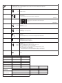
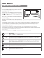
Lagernummer: 57543A 10/04 (BJ)
U S E R M AN U AL
Master with display type WLM
Introduction
The masters type WLM-1FS and WLM-3FS are provided with graphic display to
enable simple programming and operations of the unit to be achieved using
simple and easy to understand icons and symbols.
Moving around in the menu
By using the ( ) (UP), and the ( ) (DOWN) you move through the main menu into
sub menus. The description of these submenus can be seen below. If a value
needs to be changed, then press ( ) (CONFIRM) button once, and alter the value
with the ( ) (UP) and ( ) (DOWN ) buttons. Then press ( ) (CONFIRM) to accept
the new value.
If you wish to reset the master to factory settings, then push the ( ) (CONFIRM)
button for 10 sec. until the 6 outputs starts blinking. The master has now been
reset to factory settings.
Control of room temperature
Within the memory of the master, there is a room temperature Setpoint which will
apply for all rooms connected to the system. This setting is at 20°C when the unit
leaves the factory, but it can be increased or decreased as required. Any change will apply to all rooms on the system unless a clock thermostat is employed
(see next para).
Using clock thermostat (WLCT-19):
If a clock thermostat is used as a zone control for one room or a group of rooms, then all the thermostats within this zone will operate according to the
temperatures and times defined in the clock thermostat. However the local thermostats within the group are still capable of being adjusted by ± 4˚C so that
some rooms can be set higher or lower than others. The decision as to which thermostats will form part of the clock thermostats group is made by
programming the clock thermostat (see instructions for WLCT unit). Any thermostats that are not part of the clock thermostats’ group will operate to the
temperature as defined in the master control, but again with the option of local ±4°C adjustment.
Using external switch for night setback:
The day temperature set point is defaulted to 20°C and the night temperature to 15°C. These default settings can be changed on the master.
The current operating set point of the master can be changed from the day temperature into night temperature, by connecting a separate timing device to
the master. When the external switch or timer is used to switch to night setback, this will override any time settings in a WLCT clock thermostat, including
any thermostats that are part of a group allocated to that clock thermostat.
Return to main menu
If you are in a submenu and push UP (
) and DOWN ( ) at the same time you jump back to the menu start position.
20.0ºC
Day temperature
Temperature set point for all thermostats not part of a clock thermostat group.
Push ( ) accept and ( ) ( ) to adjust the set point.
15.0ºC
Night temperature
When activated via an external timer, this action is valid for all thermostats connected to the master. Night setback can also
be activated on individual thermostats (WLTM & WLTD) by using the selector switch and setting to the “night” position. A
clock thermostat (WLCT) will automatically switch to night setback at the times programmed into it, as will all the other
thermostats which are included in its group.
5.0ºC
OFF temperature (frost protection)
All thermostats with an override switch (WLTM & WLTD) can be set to an OFF position. This is known as a frost protection
position, and if the temperature in the room shoud fall as low as 5°C, the heating will be enabled to prevent frost damage.
The 5°C level can be changed in the master module.
Limitation of floor temperatures
27.0ºC
Max limit temperature for thermostats with limit sensor (floor sensor)
17.0ºC
Min limit for thermostats with limit sensor (floor sensor)
Supply Water Temperature Control
Using supply water sensor for limitation of supply water:
A limit sensor should be used with the WLM 1FS & WLM 3FS, but can be used without the weather compensation module (WLOC). In this case the
master will control the supply water temperature flowing into the system via the 3 or 4 port mixing valve and actuator. The factory default setting is 45°C,
but can be changed via the master display.
Using outdoor compensation module for weather compensation
When the outdoor compensation module (WLOC) is connected to the system, the master calculates the correct temperature, taking into account the
heat losses that will vary depending on the outdoor temperature, and the room temperature requirements of the system. For example, on a day when the
outdoor temperature is 12°C, it is possible to run the heating system with a supply water temperature of only 35°C. this ensures economical running of
the boilers, and comfortable room conditions throughout the year. The max allowed supply water temperatur prevents excessive water temperatures if
the outdoor temperature becomes extremely cold, e.g. - 30°C.
55ºC
Max allowed supply water temperature.
-3ºC
Winter
Outdoor temperature
45ºC
Winter
Design supply water temperature at outdoor temperature –3°C
Design supply water temperature if used without outdoor compensation module.
Return
25ºC
Summer
Outdoor temperature
30ºC
Summer
Supply water temperature at outdoor temperature 25ºC
Return
Max supply temperture
The max allowed supply water temperature is set according to the design
requirements of the installation (line A on the curve). This is the safely
maximum.
Weather compensation
Winter
A design outdoor temperature and the corresponding design supply
water temperature are set (point B). To increase the heat output, adjust
the supply water temperature higher, until you feel comfortable (we
recommend only a 2 degree adjustment of this temperature at a time, and
timer allowed for the system to respond).
Summer
An outdoor temperature and the corresponding supply water temperature
are set (point C). To increase the heat output, adjust the supply water
temperature higher (we recommend only a 2 degree adjustment of this
temperature at a time, and timer allowed for the system to respond)
The master calculates the intersection point D
Compensation for outdoor temperature can only be done if an outdoor
compensation module (WLOC) is installed. Without outdoor
compensation module the Master will adjust after allowed supply water
temperature 45°C.
Service menu
Push accept to enter
No setting values can be changed under the service menu. The controller will automatically return
to main menu after 30 minutes.
1.6
Software version
OK no failures
E1 to E9 if a failure is present. See below for explanation.
Submenu 2
Push accept to enter and see which unit has the
failure
Submenu 2a
-2.4°C
Read-out
Outdoor temperature
49.2ºC
Read-out
Actual supply water temperature
44.4ºC
Read-out
Calculated setpoint by the controller for the supply water temperature
3.5V
--24.0°C
22.9°C
Read-out
Control signal for the mixing valve.
At 10V the mixing valve is fully open.
Read-out
Room temperature in the different rooms.
Push accept (V) and up or down to select another room
The room temperature is shown in the middle.
If a limitation sensor is connected the measured temperature is shown
below or above the room temperature.
·
if the thermostat is for minimum limitation the value is shown below
·
If the thermostat is set for max. limitation the value is shown above.
Return
Settings
Factory settings
House temperature
20ºC
Night temperature
15°C
Off temperature
5°C
Floor Limit temp high
27°C
Floor Limit temp low
17°C
Max water temperature
55°C
Own settings
Factory settings
Weather compensation
Outdoor temperature
-3ºC
Cold (winter)
water temperature
45ºC
Weather compensation
Outdoor temperature
25ºC
Warm (summer)
water temperature
30ºC
Software version
1.60
Own settings
ERROR/FAULT MESSAGES AND TROUBLE SHOOTING
During normal operation the green power LED will be ON when the master control is energised. The red output LED’s (1 to 6 on the master, and 7 to 14 on
the add-on modules) will indicate if the channel output relay is ON/OFF.
An error / fault message is shown by flashing the green power LED or one of the 6 red output LED’s. From the number of flashes on any one LED, the
problem can be diagnosed, and identified from the following:
The error number will be indicated by the number of flashes, with a pause of less than a 1/2 second between the flashes. The indication will be followed by a
pause of 2 seconds, following which the sequence will be repeated. The failure code can also be seen in the service menu (submenu 2).
Flashing Power LED (green)
E1, 1 flash Ô One or more thermostats that are set to channel 0 or channel 15 are no longer sending data to the master control. The fault is corrected by
replacing the thermostat. The master will need to be HARD RESET (see below) (NOTE: If the thermostat is of the WIRELESS type, the error
/fault message could be an indication that the power has failed, and that the internal battery of the thermostat needs to be replaced)
E2, 2 flashes Ô One or more thermostats have been set to a channel number which does not exist in the system. For example, the message will occur if the
units are set to channels 7..14 and the required add on (AO) modules are not found in the system. The error is corrected by setting the
channel number of the thermostat to a channel that does exist within the installed master/add on module system.
E3, 3 flashes Ô Both AO modules have been set to the same channel group (either 7 to 10 or 11 to 14). The error is corrected by moving the selector switch
placed in the lower right corner of the PCB of the AO module to position A for output 7 to 10 or to position B for output 11 to 14. Only two
AO modules can be used with any one master.
E4, 4 flashes Ô The outdoor compensation module (WLOC) is defective. The fault is corrected by changing the outdoor compensation module. If the
module has been removed deliberately to change the operation of the system, follow the HARD RESET instruction below.
E5, 5 flashes Ô The external limit sensor (type ETF-1899A) is defective. The fault is corrected by changing the temperature sensor. If the sensor has been
removed deliberately to change the operation of the system, follow the HARD RESET instruction below.
E6, 6 flashes Ô Internal overheating. The master has its own internal safety temperature protection system. The problem is corrected by improving the
ventilation around the master module.
E7, 7 flashes Ô Defective internal overheat sensor. The Master will control as normal, however the protection against internal over heating is no longer
active. The fault can only be corrected by replacing the master module.
E8, 8 flashes Ô The communication to an AO module has been lost. The fault is corrected by re-establishing the connection to the AO module or by
changing the AO module if it is defective - or if it has been deliberately removed, with a HARD RESET.
E9, 9 flashes Ô Indicates total number of input units exceeded. Please refer to factory or your local service engineer.
Only one error/fault condition can be shown at a time. If more than one error occurs, they will be prioritised in the shown sequence (1..9).
Flashing output LED (red):
The appropriate output channel LED can flash, indicating that the thermostat on that channel has a fault/error. The failure code can also be seen in
the service menu (submenu 2a).
Ô The master has lost communication to the thermostat. The fault is corrected by re-establishing the connection to the thermostat and the
fault condition will be automatically reset once correct communication is resumed. If the thermostat is defective and has to be changed, or
if it has been deliberately removed, it is necessary to make a HARD RESET. (NOTE: If the thermostat is of the WIRELESS type, the error
/fault message could be an indication that the power has failed, and that the internal battery of the thermostat needs to be replaced)
E2, 2 flashes Ô The internal sensor in the thermostat is defective. The fault can only be corrected by replacing the thermostat. Remember to make a HARD
RESET after installing the new thermostat.
E3, 3 flashes Ô The limit sensor on the thermostat is defective. Replace the faulty sensor. Reset is NOT required.
E4, 4 flashes Ô Defective WLCT clock thermostat. If a clock thermostat operating a group of thermostats becomes defective, the remaining thermostats
will control within the maximum and minimum limits programmed into the clock thermostat.
E1, 1 flash
RESET
There are 3 different reset actions that can be used.
SOFT RESET
If the (V) button is activated for 3 seconds, a SOFT RESET will be initiated. (Indicated by all the red output LED’s(1-6) lighting in sequence when the ‘V’
button is released). A SOFT RESET will clear failure messages, in the next 5 minutes.
HARD RESET
If the ‘V’ button is pressed for 8 seconds, a HARD RESET will be initiated. (Indicated by flashes of all six red output LED’s and the green power LED
simultaneously). This reset will remove from the system any thermostat unit with a defective input sensor, or a defective AO module. The fault message will
be reset but the defective items will no longer participate in the system. Once a defective unit is replaced, the new unit will automatically be recognised by
the master control and become part of the system. To erase the identity of the defective component from the master memory a HARD RESET must be
performed
Hard resets do not alter the temperature settings already programmed into the master control.
FACTORY RESET
If the (V) button is pressed for more than 10 seconds, a total factory reset will be initiated. This is indicated through flashes of channel LEDs 1,3, and 5
alternating with channel LEDs 2, 4, and 6 (while the “V” button is pressed).
A factory reset will put all programmed temperature settings back to the factory defaults. It will also remove all thermostats from the master memory, and
reset the system to accept only those thermostats that are functioning correctly.
OJ Electronics A/S
Stenager 13B · DK-6400 Sønderborg
Tel +45 73 12 13 14 · Fax +45 73 12 13 13
www.oj.dk