1
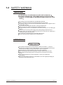
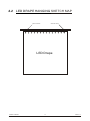
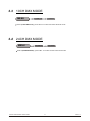
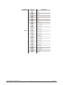
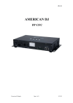
USER MANUAL
Version 1.0
www.yagang.com
drapeLED
T
ABLE OF CONTENTS
TABLE OF CONTENTS..................................................................I.
PART 1 PRODUCT (GENERAL)....................................................1.
1.1--PRODUCT INTRODUCTION.........................................................2.
1.2--PRODUCT FEATURES.................................................................2.
1.3--TECHNICAL SPECIFICATIONS.....................................................2.
1.4--SAFETY WARNING......................................................................3.
PART 2 INSTALLATION...............................................................4.
2.1-- PRODUCT OVERVIEW................................................................. 5.
2.2-- LED DRAPE HANGING SKETCH MAP........................................... 6.
2.3--DMX MODE CONNECTION........................................................... 7.
2.4--MASTER / SLAVE MODE CONNECTION........................................ 7.
PART 3 USING THE DRAPE LED SYSTEM CONTROLLER .........................8.
3.1--BASIC.........................................................................................9.
3.2--MENU......................................................................................... 10.
3.3--10CH DMX MODE........................................................................11.
3.4--24CH DMX MODE.........................................................................11.
3.5--AUTO PROGRAMS EDIT MODE....................................................12.
3.6--SLAVE MODE..............................................................................13.
3.7--SETTING.....................................................................................13.
PART 4 USING A DMX512 CONTROLLER.......................................14.
4.1--BASIC ADDRESSING...................................................................15.
4.2--CHANNEL ASSIGNMENT............................................................. 15.
PART 5 MAINTENANCE.................................................................18.
5.1--MAINTENANCE............................................................................ 19.
5.2--PARTS LIST.................................................................................19.
TABLE OF CONTENTS
I
2007.5.9
TABLE OF CONTENTS
II
2007.5.9
1
PRODUCT (GENERAL)
1.1
1.2
1.3
1.4
PRODUCT (GENERAL)
PRODUCT INTRODUCTION
PRODUCT FEATURES
TECHNICAL SPECIFICATIONS
SAFETY WARNING
1
2007.5.9
1.1
PRODUCT INTRODUCTION
This product is designed for indoor use. Suitable applications include large or small
background lighting effect for stage, opera, nightclub application. This product can be
operated as a single unit or in multiple units for large applications. Direct input of DMX512
signal to the DRAPE LED SYSTEM controller allows the units to be controlled from any
DMX512 controller. Powerful internal programs and simple to program user-programs
allow this product to meet the needs of any lighting project.
1.2
PRODUCT FEATURES
* RGB Dimmer 0-100%
*Strobe
*Master / slave / DMX512 working mode
*Powerful automatic programs
*8 User self-programmable sequences
*LCD display
*10CH DMX512 mode
*24CH DMX512 mode
1.3
TECHNICAL SPECIFICATIONS
DRAPE LED SYSTEM
DRAPE LED SYSTEM
Voltage
Rated Power
Dimensions
Weight
AC90-260V, 50/60Hz
250W
570 x 169 x 190mm
4Kg
drapeLED
drapeLED :
LED/Unit
LED life span
Dimensions
Weight
PRODUCT (GENERAL)
2
128PCS
100,000 hrs
600 x 400 x 5cm
18 Kg
2007.5.9
1.4
SAFETY WARNING
IMPORTANT
ALWAYS READ THE USER MANUAL BEFORE OPERATION.
PLEASE CONFIRM THAT THE POWER SUPPLY STATED ON THE
PRODUCT IS THE SAME AS THE MAINS POWER SUPPLY IN YOUR
AREA.
This product must be installed by a qualified professional.
Always operate the equipment as described in the user manual.
A minimum distance of 0.5m must be maintained between the equipment and
combustible surface.
The product must always be placed in a well ventilated area.
Always make sure that the equipment is installed securely.
DO NOT stand close to the equipment and stare directly into the LED light
source.
Always disconnect the power supply before attempting and maintenance.
Always make sure that the supporting structure is solid and can support the
combined weight of the products.
The earth wire must always be connected to the ground.
Do not touch the power cables if your hands are wet.
ATTENTION
This product left the place of manufacture in perfect condition. In order to
maintain this condition and for safe operation, the user must always follow the
instructions and safety warnings described in this user manual.
Avoid shaking or strong impacts to any part of the equipment.
Make sure that al parts of the equipment are kept clean and free of dust.
Always make sure that the power connections are connected correct and
secure.
If there is any malfunction of the equipment, contact your distributor
immediately.
When transferring the product, it is advisable to use the original packaging in
which the product left the factory.
PRODUCT (GENERAL)
3
2007.5.9
2
INSTALLATION
2.1
2.2
2.3
2.4
2.5
INSTALLATION
PRODUCT OVERVIEW
LED DRAPE HANGING SKETCH MAP
DMX MODE CONNECTION
DMX MASTER / SLAVE MODE CONNECTION
MASTER / SLAVE MODE CONNECTION
4
2007.5.9
2.1
PRODUCT OVERVIEW
LED DRAPE
LED STRINGS
DRIVER BOARD
ON
OUT
IN
DMX
INSTALLATION
POWER IN
DMX512
LED OUTPUTS
MENU
OFF
drape LED
system
SET
UP
DOWN
5
2007.5.9
2.2
LED DRAPE HANGING SKETCH MAP
Secure chain
Secure chain
LED Drape
INSTALLATION
6
2007.5.9
2.3 DMX MODE CONNECTION
DMX512
DRAPE
LED SYSTEM
1
DRAPE 1 DRAPE 2 DRAPE 3 DRAPE 4
DRAPE
LED SYSTEM
2
DRAPE 1 DRAPE 2 DRAPE 3 DRAPE 4
DRAPE
LED SYSTEM
3
DRAPE 1 DRAPE 2 DRAPE 3 DRAPE 4
2.4 DMX MASTER / SLAVE MODE CONNECTION
DMX512
MASTER DRAPE
LED SYSTEM
DRAPE 1 DRAPE 2 DRAPE 3
SLAVE DRAPE
LED SYSTEM 1
SLAVE DRAPE
LED SYSTEM 2
DRAPE 1 DRAPE 2 DRAPE 3 DRAPE 4
DRAPE 1 DRAPE 2 DRAPE 3 DRAPE 4
2.5 MASTER / SLAVE MODE CONNECTION
MASTER DRAPE
LED SYSTEM
DRAPE 1 DRAPE 2 DRAPE 3 DRAPE 4
INSTALLATION
SLAVE DRAPE
LED SYSTEM 1
SLAVE DRAPE
LED SYSTEM 2
DRAPE 1 DRAPE 2 DRAPE 3 DRAPE 4
DRAPE 1 DRAPE 2 DRAPE 3 DRAPE 4
7
2007.5.9
3
USING THE DRAPE LED SYSTEM
3.1
3.2
3.3
3.4
3.5
3.6
3.7
BASIC
MENU
10CH DMX MODE
24CH DMX MODE
AUTO PROGRAMS EDIT MODE
SLAVE MODE
SETTING
USING THE DRAPE LED SYSTEM
8
2007.5.9
3.1
BASIC
The DRAPE LED SYSTEM is mounted with a LCD display and 4 control buttons.
MENU
SET
UP
DOWN
menu selection or return to previous menu
enter the currently selected menu or confirm
the current function value
scroll 'UP' through the menu list or increase
the value of the current function
scroll 'DOWN' through the menu list of
decrease the value of the current function
USING THE DRAPE LED SYSTEM
9
2007.5.9
3.2
MENU
MENU
10 CH DMX mode
10 CH DMX512
24 CH DMX mode
Mode
1
Mode
2
Mode
3
24 CH DMX512
Auto
Program
1
Pattem type
Mode
4
Mode
5
Mode
6
Mode
7
Cross time
Program
8
Speed
Strobe mode
Minimum
Maximum
1 Color mode
2 Color mode
3 Color mode
Number colors
Set color 1
4 Color mode
5 Color mode
6 Color mode
Set color 2
Set color 3
7 Color mode
Full color
Set color 4
Slave mode
Slave
Settings
Set DMX address
Allow edit PROG
USING THE DRAPE LED SYSTEM
10
YES
/NO
2007.5.9
3.3
10CH DMX MODE
MENU
10 CH DMX mode
10 CH DMX512
Select (10CH DMX mode), press 'SET' to confirm and save this work mode
3.4
24CH DMX MODE
MENU
24 CH DMX mode
24 CH DMX512
Select (24CH DMX mode), press 'SET' to confirm and save this work mode
USING THE DRAPE LED SYSTEM
11
2007.5.9
3.5
AUTO PROGRAMS EDIT MODE
MENU
Auto
Program
1
Pattem type
Mode
1
Mode
2
Mode
3
Mode
4
Mode
5
Mode
6
Mode
7
Cross time
Program
8
Speed
Strobe mode
Minimum
1 Color mode
Maximum
2 Color mode
3 Color mode
Number colors
Set color 1
4 Color mode
5 Color mode
6 Color mode
Set color 2
Set color 3
7 Color mode
Full color
Set color 4
select (Program
1
-- 8
) user program edit menu, it show the specific display effect.
when (Auto edit PROG) allow edition, enter (Program Edit) menu to operate and save the
modification.
when under the multiple controller operation condition, only one controller was allowed to
be set as master controller, enter this menu the controller will be set as the master automaticly.
3.5.1 (Patterm type) mode, allow to select 7 kinds of direction mode or strobe mode.
3.5.2 (Cross Time) strobe speed or spark time, when pattern type is strobe mode, it adjust the
strobe frequency, when pattern type is direction mode, it adjust spark time.
3.5.3 (Speed) value 000
--
255
, adjust the color change speed when strobe.
3.5.4 (Minimum) minimum brightness value, value
000
3.5.5 (Maximum) maximum brightness value, value
000
-- 255
--
255
3.5.6 (Number colors) color mode, allow to select 8 color modes.
3.5.7 (Set colors 1) set one color, value
000
3.5.8 (Set colors 2) set two colors, value
--
000
--
255
255
3.5.9 (Set colors 3) set three colors, value
000
-- 255
3.5.10 (Set colors 4) set four colors, value
000
-- 255
USING THE DRAPE LED SYSTEM
12
2007.5.9
3.6
SLAVE MODE
MENU
Slave mode
Slave
Select (slave mode), press 'SET' to confirm and save this work mode
3.7
SETTING
MENU
Settings
Set DMX address
Allow edit PROG
(Set DMX address), value 000
YES /NO
-- 255
(Allow edit PROG), select (Allow edit YES ) to modify and save the user self-program
USING THE DRAPE LED SYSTEM
13
2007.5.9
4
USING A DMX512
CONTROLLER
4.1
4.2
BASIC ADDRESSING
CHANNEL ASSIGNMENT
USING A DMX512 CONTROLLER
14
2007.5.9
4.1
BASIC ADDRESSING
Connect all of the DRAPE LED SYSTEM in series using standard DMX512 signal cable
Select "10CH DMX MODE" or "24CH DMX MODE"(see section 3.2)
It is possible to have the same DMX address or independent address for each DRAPE LED SYSTEM
4.2
CHANNEL ASSIGNMENT
10 CH DMX MODE
CHANNEL
VALUE
FUNCTION
0
31
Mode[1]
32
63
Mode [2]
64
91
Mode [3]
92
127
Mode [4]
128
159
Mode [5]
160
191
Mode [6]
192
223
Mode [7]
224
255
Strobe mode
0
255
Cross time
0
255
Strobe time
3
0
255
Speed
4
0
255
Minimum
5
0
255
Maximum
0
31
1 color mode
32
63
2 color mode
64
95
3 color mode
96
127
4 color mode
128
159
Four colors flow mode
160
191
Three colors flow mode
192
223
Two colors flow mode
224
255
Full color
1
2
6
USING A DMX512 CONTROLLER
15
2007.5.9
CHANNEL
VALUE
9
Red
10
19
Yellow
20
29
Green
30
39
Cyan
40
49
Blue
50
59
Purple
60
69
White
70
79
Red & yellow
80
89
Green & yellow
90
99
Green & cyan
100
109
Blue & cyan
110
119
Red & purple
120
129
Blue & purple
130
139
White & red
140
149
White & green
150
159
White & blue
160
169
White & purple
170
179
Blue & cyan
180
189
Purple & blue
190
199
Purple & red
200
209
Cyan & blue
210
219
Green & yellow
220
229
White & cyan
230
255
RGB MAX
0
7,8,9,10
USING A DMX512 CONTROLLER
FUNCTION
16
2007.5.9
24 CH DMX MODE
CHANNEL
USING A DMX512 CONTROLLER
VALUE
FUNCTION
1
0
255
1st GROUP RED COLOR
2
0
255
1st GROUP GREEN COLOR
3
0
255
1st GROUP BLUE COLOR
4
0
255
2nd GROUP RED COLOR
5
0
255
2nd GROUP GREEN COLOR
6
0
255
2nd GROUP BLUE COLOR
7
0
255
3rd GROUP RED COLOR
8
0
255
3rd GROUP GREEN COLOR
9
0
255
3rd GROUP BLUE COLOR
10
0
255
4th GROUP RED COLOR
11
0
255
4th GROUP GREEN COLOR
12
0
255
4th GROUP BLUE COLOR
13
0
255
5th GROUP RED COLOR
14
0
255
5th GROUP GREEN COLOR
15
0
255
5th GROUP BLUE COLOR
16
0
255
6th GROUP RED COLOR
17
0
255
6th GROUP GREEN COLOR
18
0
255
6th GROUP BLUE COLOR
19
0
255
7th GROUP RED COLOR
20
0
255
7th GROUP GREEN COLOR
21
0
255
7th GROUP BLUE COLOR
22
0
255
8th GROUP RED COLOR
23
0
255
8th GROUP GREEN COLOR
24
0
255
8th GROUP BLUE COLOR
17
2007.5.9
5
MAINTENANCE
5.1
5.2
MAINTENANCE
MAINTENANCE
PARTS LIST
18
2007.5.9
5.1
MAINTENANCE
A minimum distance of 0.5m must be maintained between the equipment and combustible surface.
Always disconnect the power supply before attempting and maintenance.
The earth wire must always be connected to the ground.
Well pack the DRAPE, be careful not to put any heavy things on it.
5.2
PARTS LIST
LED DRAPE
PART ORDER No.
ITEM
26-2A-LED502DRV-00 Driver board
26-2A-LED502D-00
LED board
DRAPE LED SYSTEM
PART ORDER No.
MAINTENANCE
ITEM
16-03-0031-00
Power supply
26-2A-LED302DI-00
Display board
26-2A-LED502M-00
Main board
19
2007.5.9