1
DPO4000 Series
Digital Phosphor Oscilloscopes
User Manual
www.tektronix.com
071-1785-00
Copyright © Tektronix. All rights reserved. Licensed software products are owned by Tektronix or its subsidiaries or suppliers, and are protected by
national copyright laws and international treaty provisions.
Tektronix products are covered by U.S. and foreign patents, issued and pending. Information in this publication supersedes that in all previously
published material. Specifications and price change privileges reserved.
TEKTRONIX and TEK are registered trademarks of Tektronix, Inc.
e*Scope, iView, OpenChoice, TekSecure, and TekVPI are registered trademarks of Tektronix, Inc.
Wave Inspector is a trademark of Tektronix, Inc.
Contacting Tektronix
Tektronix, Inc.
14200 SW Karl Braun Drive
P.O. Box 500
Beaverton, OR 97077
USA
For product information, sales, service, and technical support:
In North America, call 1-800-833-9200.
Worldwide, visit www.tektronix.com to find contacts in your area.
Warranty 4
Tektronix warrants that this product will be free from defects in materials and workmanship for a period of three (3) years from the date of shipment. If
any such product proves defective during this warranty period, Tektronix, at its option, either will repair the defective product without charge for parts
and labor, or will provide a replacement in exchange for the defective product. Parts, modules and replacement products used by Tektronix for
warranty work may be new or reconditioned to like new performance. All replaced parts, modules and products become the property of Tektronix.
In order to obtain service under this warranty, Customer must notify Tektronix of the defect before the expiration of the warranty period and make
suitable arrangements for the performance of service. Customer shall be responsible for packaging and shipping the defective product to the service
center designated by Tektronix, with shipping charges prepaid. Tektronix shall pay for the return of the product to Customer if the shipment is to a
location within the country in which the Tektronix service center is located. Customer shall be responsible for paying all shipping charges, duties,
taxes, and any other charges for products returned to any other locations.
This warranty shall not apply to any defect, failure or damage caused by improper use or improper or inadequate maintenance and care. Tektronix
shall not be obligated to furnish service under this warranty a) to repair damage resulting from attempts by personnel other than Tektronix
representatives to install, repair or service the product; b) to repair damage resulting from improper use or connection to incompatible equipment; c) to
repair any damage or malfunction caused by the use of non-Tektronix supplies; or d) to service a product that has been modified or integrated with
other products when the effect of such modification or integration increases the time or difficulty of servicing the product.
THIS WARRANTY IS GIVEN BY TEKTRONIX WITH RESPECT TO THE PRODUCT IN LIEU OF ANY OTHER WARRANTIES, EXPRESS OR
IMPLIED. TEKTRONIX AND ITS VENDORS DISCLAIM ANY IMPLIED WARRANTIES OF MERCHANTABILITY OR FITNESS FOR A PARTICULAR
PURPOSE. TEKTRONIX’ RESPONSIBILITY TO REPAIR OR REPLACE DEFECTIVE PRODUCTS IS THE SOLE AND EXCLUSIVE REMEDY
PROVIDED TO THE CUSTOMER FOR BREACH OF THIS WARRANTY. TEKTRONIX AND ITS VENDORS WILL NOT BE LIABLE FOR ANY
INDIRECT, SPECIAL, INCIDENTAL, OR CONSEQUENTIAL DAMAGES IRRESPECTIVE OF WHETHER TEKTRONIX OR THE VENDOR HAS
ADVANCE NOTICE OF THE POSSIBILITY OF SUCH DAMAGES.
Table of Contents
Table of Contents
General Safety Summary . . . . . . . . . . . . . . . . . . . . . . . . . . . . . . . . . . . . . . . . . . . . . . . . . . . . . . . . . . . . . . . . . . . . . . . . . . . . . . . . . . . . . . . . . . . . . . . . . . . . . . . . . . . . . . . . . . .
Environmental Considerations . . . . . . . . . . . . . . . . . . . . . . . . . . . . . . . . . . . . . . . . . . . . . . . . . . . . . . . . . . . . . . . . . . . . . . . . . . . . . . . . . . . . . . . . . . . . . . . . . . . . . . . . . . . .
v
viii
Preface. . . . . . . . . . . . . . . . . . . . . . . . . . . . . . . . . . . . . . . . . . . . . . . . . . . . . . . . . . . . . . . . . . . . . . . . . . . . . . . . . . . . . . . . . . . . . . . . . . . . . . . . . . . . . . . . . . . . . . . . . . . . . . . . . . . . . . . x
Key Features. . . . . . . . . . . . . . . . . . . . . . . . . . . . . . . . . . . . . . . . . . . . . . . . . . . . . . . . . . . . . . . . . . . . . . . . . . . . . . . . . . . . . . . . . . . . . . . . . . . . . . . . . . . . . . . . . . . . . . . . . . . x
Where to Find More Information. . . . . . . . . . . . . . . . . . . . . . . . . . . . . . . . . . . . . . . . . . . . . . . . . . . . . . . . . . . . . . . . . . . . . . . . . . . . . . . . . . . . . . . . . . . . . . . . . . . . .
xii
Conventions Used in This Manual. . . . . . . . . . . . . . . . . . . . . . . . . . . . . . . . . . . . . . . . . . . . . . . . . . . . . . . . . . . . . . . . . . . . . . . . . . . . . . . . . . . . . . . . . . . . . . . . . . . xiii
Installation . . . . . . . . . . . . . . . . . . . . . . . . . . . . . . . . . . . . . . . . . . . . . . . . . . . . . . . . . . . . . . . . . . . . . . . . . . . . . . . . . . . . . . . . . . . . . . . . . . . . . . . . . . . . . . . . . . . . . . . . . . . . . . . . . .
Before Installation. . . . . . . . . . . . . . . . . . . . . . . . . . . . . . . . . . . . . . . . . . . . . . . . . . . . . . . . . . . . . . . . . . . . . . . . . . . . . . . . . . . . . . . . . . . . . . . . . . . . . . . . . . . . . . . . . . . . .
Operating Considerations . . . . . . . . . . . . . . . . . . . . . . . . . . . . . . . . . . . . . . . . . . . . . . . . . . . . . . . . . . . . . . . . . . . . . . . . . . . . . . . . . . . . . . . . . . . . . . . . . . . . . . . . . . . .
Connecting Probes . . . . . . . . . . . . . . . . . . . . . . . . . . . . . . . . . . . . . . . . . . . . . . . . . . . . . . . . . . . . . . . . . . . . . . . . . . . . . . . . . . . . . . . . . . . . . . . . . . . . . . . . . . . . . . . . . .
Powering On the Oscilloscope . . . . . . . . . . . . . . . . . . . . . . . . . . . . . . . . . . . . . . . . . . . . . . . . . . . . . . . . . . . . . . . . . . . . . . . . . . . . . . . . . . . . . . . . . . . . . . . . . . . . . .
Powering Off the Oscilloscope . . . . . . . . . . . . . . . . . . . . . . . . . . . . . . . . . . . . . . . . . . . . . . . . . . . . . . . . . . . . . . . . . . . . . . . . . . . . . . . . . . . . . . . . . . . . . . . . . . . . . .
Functional Check . . . . . . . . . . . . . . . . . . . . . . . . . . . . . . . . . . . . . . . . . . . . . . . . . . . . . . . . . . . . . . . . . . . . . . . . . . . . . . . . . . . . . . . . . . . . . . . . . . . . . . . . . . . . . . . . . . . .
Compensating the Probe . . . . . . . . . . . . . . . . . . . . . . . . . . . . . . . . . . . . . . . . . . . . . . . . . . . . . . . . . . . . . . . . . . . . . . . . . . . . . . . . . . . . . . . . . . . . . . . . . . . . . . . . . . . .
Installing an Application Module. . . . . . . . . . . . . . . . . . . . . . . . . . . . . . . . . . . . . . . . . . . . . . . . . . . . . . . . . . . . . . . . . . . . . . . . . . . . . . . . . . . . . . . . . . . . . . . . . . . . .
Changing the User Interface Language . . . . . . . . . . . . . . . . . . . . . . . . . . . . . . . . . . . . . . . . . . . . . . . . . . . . . . . . . . . . . . . . . . . . . . . . . . . . . . . . . . . . . . . . . . . . .
Changing the Date and Time . . . . . . . . . . . . . . . . . . . . . . . . . . . . . . . . . . . . . . . . . . . . . . . . . . . . . . . . . . . . . . . . . . . . . . . . . . . . . . . . . . . . . . . . . . . . . . . . . . . . . . . .
Signal Path Compensation . . . . . . . . . . . . . . . . . . . . . . . . . . . . . . . . . . . . . . . . . . . . . . . . . . . . . . . . . . . . . . . . . . . . . . . . . . . . . . . . . . . . . . . . . . . . . . . . . . . . . . . . . .
Upgrading Firmware . . . . . . . . . . . . . . . . . . . . . . . . . . . . . . . . . . . . . . . . . . . . . . . . . . . . . . . . . . . . . . . . . . . . . . . . . . . . . . . . . . . . . . . . . . . . . . . . . . . . . . . . . . . . . . . . .
Connecting Your Oscilloscope to a Computer . . . . . . . . . . . . . . . . . . . . . . . . . . . . . . . . . . . . . . . . . . . . . . . . . . . . . . . . . . . . . . . . . . . . . . . . . . . . . . . . . . . . . .
DPO4000 Series User Manual
1
1
6
10
11
14
15
17
19
20
23
25
28
34
i
Table of Contents
ii
Get Acquainted with the Instrument. . . . . . . . . . . . . . . . . . . . . . . . . . . . . . . . . . . . . . . . . . . . . . . . . . . . . . . . . . . . . . . . . . . . . . . . . . . . . . . . . . . . . . . . . . . . . . . . . . . . . . .
Front-Panel Menus and Controls . . . . . . . . . . . . . . . . . . . . . . . . . . . . . . . . . . . . . . . . . . . . . . . . . . . . . . . . . . . . . . . . . . . . . . . . . . . . . . . . . . . . . . . . . . . . . . . . . . . .
Front-Panel Connectors . . . . . . . . . . . . . . . . . . . . . . . . . . . . . . . . . . . . . . . . . . . . . . . . . . . . . . . . . . . . . . . . . . . . . . . . . . . . . . . . . . . . . . . . . . . . . . . . . . . . . . . . . . . . .
Side-Panel Connector . . . . . . . . . . . . . . . . . . . . . . . . . . . . . . . . . . . . . . . . . . . . . . . . . . . . . . . . . . . . . . . . . . . . . . . . . . . . . . . . . . . . . . . . . . . . . . . . . . . . . . . . . . . . . . .
Rear-Panel Connectors. . . . . . . . . . . . . . . . . . . . . . . . . . . . . . . . . . . . . . . . . . . . . . . . . . . . . . . . . . . . . . . . . . . . . . . . . . . . . . . . . . . . . . . . . . . . . . . . . . . . . . . . . . . . . .
45
45
66
67
68
Acquire the Signal . . . . . . . . . . . . . . . . . . . . . . . . . . . . . . . . . . . . . . . . . . . . . . . . . . . . . . . . . . . . . . . . . . . . . . . . . . . . . . . . . . . . . . . . . . . . . . . . . . . . . . . . . . . . . . . . . . . . . . . . .
Setting Up Signal Input . . . . . . . . . . . . . . . . . . . . . . . . . . . . . . . . . . . . . . . . . . . . . . . . . . . . . . . . . . . . . . . . . . . . . . . . . . . . . . . . . . . . . . . . . . . . . . . . . . . . . . . . . . . . . .
Using the Default Setup . . . . . . . . . . . . . . . . . . . . . . . . . . . . . . . . . . . . . . . . . . . . . . . . . . . . . . . . . . . . . . . . . . . . . . . . . . . . . . . . . . . . . . . . . . . . . . . . . . . . . . . . . . . . .
Using Autoset . . . . . . . . . . . . . . . . . . . . . . . . . . . . . . . . . . . . . . . . . . . . . . . . . . . . . . . . . . . . . . . . . . . . . . . . . . . . . . . . . . . . . . . . . . . . . . . . . . . . . . . . . . . . . . . . . . . . . . . .
Acquisition Concepts . . . . . . . . . . . . . . . . . . . . . . . . . . . . . . . . . . . . . . . . . . . . . . . . . . . . . . . . . . . . . . . . . . . . . . . . . . . . . . . . . . . . . . . . . . . . . . . . . . . . . . . . . . . . . . . .
How the Acquisition Modes Work . . . . . . . . . . . . . . . . . . . . . . . . . . . . . . . . . . . . . . . . . . . . . . . . . . . . . . . . . . . . . . . . . . . . . . . . . . . . . . . . . . . . . . . . . . . . . . . . . . .
Changing the Acquisition Mode and Record Length. . . . . . . . . . . . . . . . . . . . . . . . . . . . . . . . . . . . . . . . . . . . . . . . . . . . . . . . . . . . . . . . . . . . . . . . . . . . . . . .
Using Roll Mode . . . . . . . . . . . . . . . . . . . . . . . . . . . . . . . . . . . . . . . . . . . . . . . . . . . . . . . . . . . . . . . . . . . . . . . . . . . . . . . . . . . . . . . . . . . . . . . . . . . . . . . . . . . . . . . . . . . . .
Defining a Serial Bus . . . . . . . . . . . . . . . . . . . . . . . . . . . . . . . . . . . . . . . . . . . . . . . . . . . . . . . . . . . . . . . . . . . . . . . . . . . . . . . . . . . . . . . . . . . . . . . . . . . . . . . . . . . . . . . .
70
70
73
74
75
78
80
83
84
Trigger Setup and Run . . . . . . . . . . . . . . . . . . . . . . . . . . . . . . . . . . . . . . . . . . . . . . . . . . . . . . . . . . . . . . . . . . . . . . . . . . . . . . . . . . . . . . . . . . . . . . . . . . . . . . . . . . . . . . . . . . . .
Triggering Concepts . . . . . . . . . . . . . . . . . . . . . . . . . . . . . . . . . . . . . . . . . . . . . . . . . . . . . . . . . . . . . . . . . . . . . . . . . . . . . . . . . . . . . . . . . . . . . . . . . . . . . . . . . . . . . . . . .
Choosing a Trigger. . . . . . . . . . . . . . . . . . . . . . . . . . . . . . . . . . . . . . . . . . . . . . . . . . . . . . . . . . . . . . . . . . . . . . . . . . . . . . . . . . . . . . . . . . . . . . . . . . . . . . . . . . . . . . . . . . .
Selecting Triggers. . . . . . . . . . . . . . . . . . . . . . . . . . . . . . . . . . . . . . . . . . . . . . . . . . . . . . . . . . . . . . . . . . . . . . . . . . . . . . . . . . . . . . . . . . . . . . . . . . . . . . . . . . . . . . . . . . . .
Triggering on Buses . . . . . . . . . . . . . . . . . . . . . . . . . . . . . . . . . . . . . . . . . . . . . . . . . . . . . . . . . . . . . . . . . . . . . . . . . . . . . . . . . . . . . . . . . . . . . . . . . . . . . . . . . . . . . . . .
Checking Trigger Status . . . . . . . . . . . . . . . . . . . . . . . . . . . . . . . . . . . . . . . . . . . . . . . . . . . . . . . . . . . . . . . . . . . . . . . . . . . . . . . . . . . . . . . . . . . . . . . . . . . . . . . . . . . .
Using A (Main) and B (Delayed) Triggers . . . . . . . . . . . . . . . . . . . . . . . . . . . . . . . . . . . . . . . . . . . . . . . . . . . . . . . . . . . . . . . . . . . . . . . . . . . . . . . . . . . . . . . . . .
Starting and Stopping an Acquisition. . . . . . . . . . . . . . . . . . . . . . . . . . . . . . . . . . . . . . . . . . . . . . . . . . . . . . . . . . . . . . . . . . . . . . . . . . . . . . . . . . . . . . . . . . . . . . .
91
91
98
99
102
107
107
111
DPO4000 Series User Manual
Table of Contents
Display Waveform Data . . . . . . . . . . . . . . . . . . . . . . . . . . . . . . . . . . . . . . . . . . . . . . . . . . . . . . . . . . . . . . . . . . . . . . . . . . . . . . . . . . . . . . . . . . . . . . . . . . . . . . . . . . . . . . . . . .
Adding and Removing a Waveform . . . . . . . . . . . . . . . . . . . . . . . . . . . . . . . . . . . . . . . . . . . . . . . . . . . . . . . . . . . . . . . . . . . . . . . . . . . . . . . . . . . . . . . . . . . . . . . .
Setting the Display Style and Persistence . . . . . . . . . . . . . . . . . . . . . . . . . . . . . . . . . . . . . . . . . . . . . . . . . . . . . . . . . . . . . . . . . . . . . . . . . . . . . . . . . . . . . . . . .
Setting Waveform and Graticule Intensity. . . . . . . . . . . . . . . . . . . . . . . . . . . . . . . . . . . . . . . . . . . . . . . . . . . . . . . . . . . . . . . . . . . . . . . . . . . . . . . . . . . . . . . . . .
Setting the Graticule Style . . . . . . . . . . . . . . . . . . . . . . . . . . . . . . . . . . . . . . . . . . . . . . . . . . . . . . . . . . . . . . . . . . . . . . . . . . . . . . . . . . . . . . . . . . . . . . . . . . . . . . . . . .
Setting the LCD Backlight . . . . . . . . . . . . . . . . . . . . . . . . . . . . . . . . . . . . . . . . . . . . . . . . . . . . . . . . . . . . . . . . . . . . . . . . . . . . . . . . . . . . . . . . . . . . . . . . . . . . . . . . . .
Scaling and Positioning a Waveform . . . . . . . . . . . . . . . . . . . . . . . . . . . . . . . . . . . . . . . . . . . . . . . . . . . . . . . . . . . . . . . . . . . . . . . . . . . . . . . . . . . . . . . . . . . . . . .
Setting Input Parameters . . . . . . . . . . . . . . . . . . . . . . . . . . . . . . . . . . . . . . . . . . . . . . . . . . . . . . . . . . . . . . . . . . . . . . . . . . . . . . . . . . . . . . . . . . . . . . . . . . . . . . . . . . .
112
112
112
115
117
118
120
122
Analyze Waveform Data. . . . . . . . . . . . . . . . . . . . . . . . . . . . . . . . . . . . . . . . . . . . . . . . . . . . . . . . . . . . . . . . . . . . . . . . . . . . . . . . . . . . . . . . . . . . . . . . . . . . . . . . . . . . . . . . . .
Taking Automatic Measurements. . . . . . . . . . . . . . . . . . . . . . . . . . . . . . . . . . . . . . . . . . . . . . . . . . . . . . . . . . . . . . . . . . . . . . . . . . . . . . . . . . . . . . . . . . . . . . . . . . .
Selecting Automatic Measurements. . . . . . . . . . . . . . . . . . . . . . . . . . . . . . . . . . . . . . . . . . . . . . . . . . . . . . . . . . . . . . . . . . . . . . . . . . . . . . . . . . . . . . . . . . . . . . . .
Customizing an Automatic Measurement . . . . . . . . . . . . . . . . . . . . . . . . . . . . . . . . . . . . . . . . . . . . . . . . . . . . . . . . . . . . . . . . . . . . . . . . . . . . . . . . . . . . . . . . . .
Taking Manual Measurements with Cursors . . . . . . . . . . . . . . . . . . . . . . . . . . . . . . . . . . . . . . . . . . . . . . . . . . . . . . . . . . . . . . . . . . . . . . . . . . . . . . . . . . . . . . .
Using Math Waveforms . . . . . . . . . . . . . . . . . . . . . . . . . . . . . . . . . . . . . . . . . . . . . . . . . . . . . . . . . . . . . . . . . . . . . . . . . . . . . . . . . . . . . . . . . . . . . . . . . . . . . . . . . . . . .
Using FFT . . . . . . . . . . . . . . . . . . . . . . . . . . . . . . . . . . . . . . . . . . . . . . . . . . . . . . . . . . . . . . . . . . . . . . . . . . . . . . . . . . . . . . . . . . . . . . . . . . . . . . . . . . . . . . . . . . . . . . . . . . .
Using Advanced Math . . . . . . . . . . . . . . . . . . . . . . . . . . . . . . . . . . . . . . . . . . . . . . . . . . . . . . . . . . . . . . . . . . . . . . . . . . . . . . . . . . . . . . . . . . . . . . . . . . . . . . . . . . . . . .
Using Reference Waveforms . . . . . . . . . . . . . . . . . . . . . . . . . . . . . . . . . . . . . . . . . . . . . . . . . . . . . . . . . . . . . . . . . . . . . . . . . . . . . . . . . . . . . . . . . . . . . . . . . . . . . . .
Managing Long Record Length Waveforms. . . . . . . . . . . . . . . . . . . . . . . . . . . . . . . . . . . . . . . . . . . . . . . . . . . . . . . . . . . . . . . . . . . . . . . . . . . . . . . . . . . . . . . .
129
129
131
137
144
150
153
157
160
163
Save and Recall Information . . . . . . . . . . . . . . . . . . . . . . . . . . . . . . . . . . . . . . . . . . . . . . . . . . . . . . . . . . . . . . . . . . . . . . . . . . . . . . . . . . . . . . . . . . . . . . . . . . . . . . . . . . . . .
Saving a Screen Image . . . . . . . . . . . . . . . . . . . . . . . . . . . . . . . . . . . . . . . . . . . . . . . . . . . . . . . . . . . . . . . . . . . . . . . . . . . . . . . . . . . . . . . . . . . . . . . . . . . . . . . . . . . . .
Saving and Recalling Waveform Data. . . . . . . . . . . . . . . . . . . . . . . . . . . . . . . . . . . . . . . . . . . . . . . . . . . . . . . . . . . . . . . . . . . . . . . . . . . . . . . . . . . . . . . . . . . . . .
Saving and Recalling Setups . . . . . . . . . . . . . . . . . . . . . . . . . . . . . . . . . . . . . . . . . . . . . . . . . . . . . . . . . . . . . . . . . . . . . . . . . . . . . . . . . . . . . . . . . . . . . . . . . . . . . . .
174
174
176
184
DPO4000 Series User Manual
iii
Table of Contents
Saving with One Button Push . . . . . . . . . . . . . . . . . . . . . . . . . . . . . . . . . . . . . . . . . . . . . . . . . . . . . . . . . . . . . . . . . . . . . . . . . . . . . . . . . . . . . . . . . . . . . . . . . . . . . .
Printing a Hard Copy. . . . . . . . . . . . . . . . . . . . . . . . . . . . . . . . . . . . . . . . . . . . . . . . . . . . . . . . . . . . . . . . . . . . . . . . . . . . . . . . . . . . . . . . . . . . . . . . . . . . . . . . . . . . . . . .
Erasing DPO4000 Memory . . . . . . . . . . . . . . . . . . . . . . . . . . . . . . . . . . . . . . . . . . . . . . . . . . . . . . . . . . . . . . . . . . . . . . . . . . . . . . . . . . . . . . . . . . . . . . . . . . . . . . . . .
187
189
196
Use Application Modules . . . . . . . . . . . . . . . . . . . . . . . . . . . . . . . . . . . . . . . . . . . . . . . . . . . . . . . . . . . . . . . . . . . . . . . . . . . . . . . . . . . . . . . . . . . . . . . . . . . . . . . . . . . . . . . . .
200
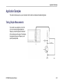
Application Examples. . . . . . . . . . . . . . . . . . . . . . . . . . . . . . . . . . . . . . . . . . . . . . . . . . . . . . . . . . . . . . . . . . . . . . . . . . . . . . . . . . . . . . . . . . . . . . . . . . . . . . . . . . . . . . . . . . . . .
Taking Simple Measurements . . . . . . . . . . . . . . . . . . . . . . . . . . . . . . . . . . . . . . . . . . . . . . . . . . . . . . . . . . . . . . . . . . . . . . . . . . . . . . . . . . . . . . . . . . . . . . . . . . . . . .
Analyzing Signal Detail . . . . . . . . . . . . . . . . . . . . . . . . . . . . . . . . . . . . . . . . . . . . . . . . . . . . . . . . . . . . . . . . . . . . . . . . . . . . . . . . . . . . . . . . . . . . . . . . . . . . . . . . . . . . .
Triggering on a Video Signal . . . . . . . . . . . . . . . . . . . . . . . . . . . . . . . . . . . . . . . . . . . . . . . . . . . . . . . . . . . . . . . . . . . . . . . . . . . . . . . . . . . . . . . . . . . . . . . . . . . . . . .
Capturing a Single-Shot Signal. . . . . . . . . . . . . . . . . . . . . . . . . . . . . . . . . . . . . . . . . . . . . . . . . . . . . . . . . . . . . . . . . . . . . . . . . . . . . . . . . . . . . . . . . . . . . . . . . . . . .
Correlating Data With a TLA5000 Logic Analyzer . . . . . . . . . . . . . . . . . . . . . . . . . . . . . . . . . . . . . . . . . . . . . . . . . . . . . . . . . . . . . . . . . . . . . . . . . . . . . . . . .
Tracking Down Bus Anomalies . . . . . . . . . . . . . . . . . . . . . . . . . . . . . . . . . . . . . . . . . . . . . . . . . . . . . . . . . . . . . . . . . . . . . . . . . . . . . . . . . . . . . . . . . . . . . . . . . . . . .
201
201
217
226
230
235
238
Index
iv
DPO4000 Series User Manual
General Safety Summary
General Safety Summary
Review the following safety precautions to avoid injury and prevent damage to this product or any products connected to it.
To avoid potential hazards, use this product only as specified.
Only qualified personnel should perform service procedures.
To Avoid Fire or Personal Injury
Use Proper Power Cord. Use only the power cord specified for this product and certified for the country of use.
Connect and Disconnect Properly. Do not connect or disconnect probes or test leads while they are connected to a voltage
source.
Connect and Disconnect Properly. De-energize the circuit under test before connecting or disconnecting the current probe.
Ground the Product. This product is grounded through the grounding conductor of the power cord. To avoid electric shock,
the grounding conductor must be connected to earth ground. Before making connections to the input or output terminals of
the product, ensure that the product is properly grounded.
Observe All Terminal Ratings. To avoid fire or shock hazard, observe all ratings and markings on the product. Consult the
product manual for further ratings information before making connections to the product.
The inputs are not rated for connection to mains or Category II, III, or IV circuits.
Connect the probe reference lead to earth ground only.
Do not apply a potential to any terminal, including the common terminal, that exceeds the maximum rating of that terminal.
DPO4000 Series User Manual
v
General Safety Summary
Power Disconnect. The power switch disconnects the product from the power source. See instructions for the location. Do not
block the power switch; it must remain accessible to the user at all times.
Do Not Operate Without Covers. Do not operate this product with covers or panels removed.
Do Not Operate With Suspected Failures. If you suspect that there is damage to this product, have it inspected by qualified
service personnel.
Avoid Exposed Circuitry. Do not touch exposed connections and components when power is present.
Do Not Operate in Wet/Damp Conditions.
Do Not Operate in an Explosive Atmosphere.
Keep Product Surfaces Clean and Dry.
Provide Proper Ventilation. Refer to the manual’s installation instructions for details on installing the product so it has proper
ventilation.
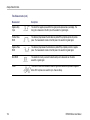
Terms in this Manual
These terms may appear in this manual:
WARNING. Warning statements identify conditions or practices that could result in injury or loss of life.
CAUTION. Caution statements identify conditions or practices that could result in damage to this product or other property.
vi
DPO4000 Series User Manual
General Safety Summary
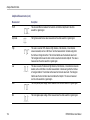
Symbols and Terms on the Product
These terms may appear on the product:
DANGER indicates an injury hazard immediately accessible as you read the marking.
WARNING indicates an injury hazard not immediately accessible as you read the marking.
CAUTION indicates a hazard to property including the product.
The following symbols may appear on the product:
DPO4000 Series User Manual
vii
Environmental Considerations
Environmental Considerations
This section provides information about the environmental impact of the product.
Product End-of-Life Handling
Observe the following guidelines when recycling an instrument or component:
Equipment Recycling. Production of this equipment required the extraction and use of natural resources. The equipment may
contain substances that could be harmful to the environment or human health if improperly handled at the product’s end of life. In
order to avoid release of such substances into the environment and to reduce the use of natural resources, we encourage you to
recycle this product in an appropriate system that will ensure that most of the materials are reused or recycled appropriately.
The symbol shown below indicates that this product complies with the European Union’s requirements according to Directive
2002/96/EC on waste electrical and electronic equipment (WEEE). For information about recycling options, check the
Support/Service section of the Tektronix Web site (www.tektronix.com).
Mercury Notification. This product uses an LCD backlight lamp that contains mercury. Disposal may be regulated due
to environmental considerations. Please contact your local authorities or, within the United States, the Electronics Industries
Alliance (www.eiae.org) for disposal or recycling information.
viii
DPO4000 Series User Manual
Environmental Considerations
Restriction of Hazardous Substances
This product has been classified as Monitoring and Control equipment, and is outside the scope of the 2002/95/EC RoHS Directive.
This product is known to contain lead, cadmium, mercury, and hexavalent chromium.
DPO4000 Series User Manual
ix
Preface
Preface
This manual describes the installation and operation of the following DPO4000 Series Instruments:
DPO4104
DPO4054
DPO4034
DPO4032
Key Features
DPO4000 Series instruments can help you verify, debug, and characterize electronic designs. Key features include:
1 GHz, 500 MHz, and 350 MHz bandwidths
2 and 4 channel models
Sample rates up to 5 GS/s on all channels
10 Megapoint record length on all channels
I2C, SPI, and CAN serial triggering and analysis
(Requires use of the DPO4EMBD (for I2C and SPI) or DPO4AUTO (for CAN) application modules)
Wave Inspector controls for managing long record lengths, with zoom and pan, play and pause, search and mark
10.4 inch (264 mm) XGA color display
Small footprint and lightweight, at 140 mm (5.5 inches) deep and 5 kg (11 pounds)
USB and CompactFlash available for quick and easy storage
Built-in Ethernet port
USB 2.0 device port for direct PC control of the oscilloscope using USBTMC protocol
x
DPO4000 Series User Manual
Preface
OpenChoice documentation and analysis software
Remote viewing with control (e*Scope and OpenChoice connectivity)
TekVPI Versatile Probe Interface supports active, differential, and current probes for automatic scaling and units
DPO4000 Series User Manual
xi
Preface
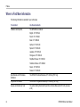
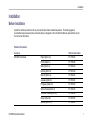
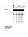
Where to Find More Information
The following information is available for your oscilloscope:
xii
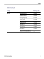
To read about
Use these documents
Installation and Operation
This DPO4000 User Manual
English: 071-1785-XX
French: 071-1799-XX
Italian: 071-1800-XX
German: 071-1801-XX
Spanish: 071-1802-XX
Japanese: 071-1803-XX
Portuguese: 071-1804-XX
Simplified Chinese: 071-1805-XX
Traditional Chinese: 071-1806-XX
Korean: 071-1807-XX
Russian: 071-1808-XX
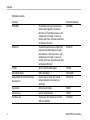
Specifications and Performance
Verification
The DPO4000 Technical Reference (071-1843-XX) (PDF only)
Programmer Commands
The DPO4000 Programmer Manual (071-1845-XX) (PDF only)
Analysis and Connectivity Tools
The optional Getting Started with OpenChoice Solutions Manual (020-2514-XX) (includes
a CD)
DPO4000 Series User Manual
Preface
To read about
Use these documents
Servicing and calibration
The optional DPO4000 Service Manual (071-1844-XX)
Installing and testing application
modules
The DPO4000 Series Application Module Installation Instructions manual (071-1833-XX)
(11 languages)
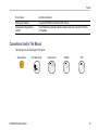
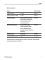
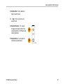
Conventions Used in This Manual
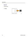
The following icons are used throughout this manual.
Sequence Step
DPO4000 Series User Manual
Front panel power
Connect power
Network
USB
xiii
Preface
xiv
DPO4000 Series User Manual
Installation
Installation
Before Installation
Unpack the oscilloscope and check that you received all items listed as standard accessories. The following pages list
recommended accessories and probes, instrument options, and upgrades. Check the Tektronix Web site (www.tektronix.com) for
the most current information.
Standard Accessories
Accessory
DPO4000 User Manual
DPO4000 Series User Manual
Tektronix part number
English (Option L0)
071-1785-XX
French (Option L1)
071-1799-XX
Italian (Option L2)
071-1800-XX
German (Option L3)
071-1801-XX
Spanish (Option L4)
071-1802-XX
Japanese (Option L5)
071-1803-XX
Portuguese (Option L6)
071-1804-XX
Simple Chinese (Option L7)
071-1805-XX
Traditional Chinese (Option L8)
071-1806-XX
Korean (Option L9)
071-1807-XX
Russian (Option L10)
071-1808-XX
1
Installation
Standard Accessories (cont.)
Accessory
2
Tektronix part number
DPO4000 Documentation Browser CD
Electronic versions of DPO4000 documents,
including the Programmer Manual and the
Technical Reference.
063-1810-XX
OpenChoice Desktop CD
Applications that let you capture and transfer data
from your oscilloscope to an external PC. Use the
standalone OpenChoice Desktop, MS Word, or
MS Excel Toolbars.
020-2514-XX
Calibration certificate documenting traceability
to national metrology institute(s), and ISO9001
quality system registration.
——
One 500 MHz, 10x passive probe per channel
P6139A
Front Cover
Hard plastic cover to help protect the instrument
200-4908-00
CompactFlash memory card
Extra storage
156-9413-00
DPO4000 Series User Manual
Installation
Standard Accessories (cont.)
Accessory
Power Cord
Tektronix part number
North America (Option A0)
161-0104-00
Universal Euro (Option A1)
161-0104-06
United Kingdom (Option A2)
161-0104-07
Australia (Option A3)
161-0104-05
Switzerland (Option A5)
161-0167-00
Japan (Option A6)
161-A005-00
China (Option A10)
161-0306-00
India (Option A11)
161-0400-00
——
No power cord or AC adapter (Option A99)
DPO4000 Series User Manual
3
Installation
Optional Accessories
Accessory
4
Tektronix Part Number
DPO4EMBD
The embedded serial triggering and analysis
module enables triggering on packet level
information on I2C and SPI serial buses, as well
as digital views of the signal, bus views, bus
decoding, search tools, and packet decode tables
with timestamp information
DPO4EMBD
DPO4AUTO
The embedding automotive serial triggering and
analysis module enables triggering on packet
level information on CAN serial buses, as well
as digital views of the signal, bus views, bus
decoding, search tools, and packet decode tables
with timestamp information
DPO4AUTO
TPA-BNC
TekVPI to TekProbe 2 BNC Adapter
TPA-BNC
TEK-USB-488 Adapter
GPIB to USB Adapter
TEK-USB-488
Getting Started with OpenChoice Solutions
Manual with CD
Describes ways to develop host-computer
software applications that work with your
oscilloscope
020-2513-XX
Rackmount kit
Adds rackmount brackets
RM4000
Soft transit case
Case for carrying instrument
AC4000
Hard transit case
Traveling case, which requires use of the soft
transit case (AC4000)
HCTEK4321
DPO4000 Series User Manual
Installation
Optional Accessories (cont.)
Accessory
Tektronix Part Number
CompactFlash memory card
Extra storage
156-9413-00
CompactFlash to USB memory card reader
Card reader
119-6827-00
DPO4000 Programmer Manual
Describes commands for remote control of the
DPO4000 oscilloscope. Available electronically
on the Documentation Browser CD or for
download from www.tektronix.com.
071-1845-XX
DPO4000 Technical Reference Manual
Describes the DPO4000 oscilloscope
specifications and performance verification
procedure. Available electronically on the
Documentation Browser CD or for download from
www.tektronix.com.
071-1809-XX
DPO4000 Service manual
Service information
071-1844-XX
DPO4000 Module Installation Instructions
Manual
071-1833-XX
The DPO4000 oscilloscope works with multiple optional probes. (See page 10, Connecting Probes.) Check the Tektronix Web
site (www.tektronix.com) for the most current information.
DPO4000 Series User Manual
5
Installation
Operating Considerations
DPO4000 Series Oscilloscope
Input Voltage: 100 V to 240 V ±10%
Input Power Frequency:
47 Hz to 66 Hz (100 V to 240 V)
400 Hz (100 V to 132 V)
Power Consumption: 250 W maximum
Weight: 5 kg (11 lbs), stand-alone instrument
Height, including feet but not handle:
229 mm (9.0 in)
Width, from handle hub to handle hub: 439 mm
(17.3 in)
Depth, from feet to front of knobs: 137 mm
(5.4 in)
Depth, from feet to front of front cover: 145 mm
(5.7 in)
Clearance: 51 mm (2 in)
Temperature:
Operating: +0 °C to +50 °C
Nonoperating: -20 °C to +60 °C
6
DPO4000 Series User Manual
Installation
Humidity:
Operating: High: 40 °C to 50 °C, 10% to 60% RH
Operating: Low: 0 °C to 40 °C, 10 to 90% RH
Non-operating: High: 40 °C to 60 °C, 5 to 60% RH
Non-operating: Low: 0 °C to 40 °C, 5 to 90% RH
Altitude:
Operating: 3,000 m (about 10,000 ft)
Nonoperating Altitude: 12,192 m (40,000 ft)
Random Vibration:
Operating: 0.31 GRMS, 5 – 500 Hz, 10 minutes per axis, 3 axes (30 minutes total)
Non-operating: 2.46 GRMS, 5 – 500 Hz, 10 minutes per axis, 3 axes (30 minutes total)
Pollution Degree: 2, Indoor use only
Acquisition System: 1 MΩ
The maximum input voltage at the BNC, between center conductor and shield is 400 Vpeak (DF ≤ 39.2%), 250 VRMS to 130 kHz
derated to 2.6 V RMS at 500 MHz.
The maximum transient withstand voltage is ± 800 Vpeak.
For steady-state sinusoidal waveforms, derate at 20 dB/decade above 200 kHz to 13 Vpk at 3 MHz and above.
Acquisition System: 50Ω
The maximum input voltage at the BNC, between center conductor and shield is 5 VRMS, with peaks ≤ ±20 V (DF ≤ 6.25%)
DPO4000 Series User Manual
7
Installation
External Trigger: 1 MΩ
The maximum input voltage at the BNC, between center conductor and shield is 400 Vpeak (DF ≤ 39.2%), 250 VRMS to 2 MHz
derated to 5 VRMS at 500 MHz.
The maximum transient withstand voltage is ±800 Vpeak.
For steady-state sinosoidal waveforms, derate at 20 dB/decade above 200 kHz to 13 Vpeak at 3 MHz and above.
P6139A Passive Probe
Input Voltage:
400 VRMS or 400 V DC; CAT I (2,500 Vpeak transient)
300 VRMS or 300 V DC; CAT II (2,500 Vpeak transient
150 VRMS or 150 V DC; CAT III (2,500 Vpeak transient)
For steady-state, sinusoidal waveforms, derate at 20 dB/decade above 2.5 MHz to 50 VRMS at 20 MHz and above.
Output Voltage (terminated into 1 MΩ):
40 VRMS or 40 V DC; CAT I (2,500 Vpeak impulse)
30 VRMS or 30 V DC; CAT I (250 Vpeak impulse)
15 VRMS or 15 V DC; CAT I (250 Vpeak impulse)
Temperature:
Operating: -15 °C to +65 °C ( +5 °F to +149 °F)
Nonoperating: -62 °C to +85 °C ( -80 °F to +185 °F)
Altitude: ≤ 2,000 meters
8
DPO4000 Series User Manual
Installation
Pollution Degree: 2, Indoor use only
Humidity:
Operating: High: 40 °C to 50 °C, 10% to 60% RH
Operating: Low: 0 °C to 40 °C, 10 to 90% RH
CAUTION. To ensure proper cooling, keep the sides and rear of the instrument clear of obstructions.
Cleaning
Inspect the oscilloscope and probes as often as operating conditions require. To clean the exterior surface, perform the following
steps:
1. Remove loose dust on the outside of the oscilloscope and probes with a lint-free cloth. Use care to avoid scratching the clear
glass display filter.
2. Use a soft cloth dampened with water to clean the oscilloscope. Use an aqueous solution of 75% isopropyl alcohol for
more efficient cleaning.
CAUTION. To avoid damage to the surface of the oscilloscope or probes, do not use any abrasive or chemical cleaning agents.
DPO4000 Series User Manual
9
Installation
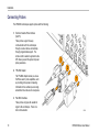
Connecting Probes
The DPO4000 oscilloscope supports probes with the following:
1. Tektronix Versatile Probe Interface
(TekVPI)
These probes support two-way
communication with the oscilloscope
through on-screen menus and remotely
through programmable support. The
remote control is useful in applications like
ATE where you want the system to preset
probe parameters.
2. TPA-BNC Adapter
The TPA-BNC Adapter allows you to use
TekProbe Level II probe capabilities, such
as providing probe power and passing
information to the oscilloscope on scaling
and whether the units are volts or amperes.
3. Plain BNC interfaces
These probes only pass the waveform
signal to the oscilloscope. There is no
other communication.
10
DPO4000 Series User Manual
Installation
For more information on the many probes available for use with DPO4000 oscilloscopes, refer to www.tektronix.com.
Powering On the Oscilloscope
Ground the Oscilloscope and Yourself
Before pushing the power switch, connect the oscilloscope to an electrically neutral reference point, such as earth ground. Do this
by plugging the three-pronged power cord into an outlet grounded to earth ground.
Grounding the oscilloscope is necessary for safety and to take accurate measurements. The oscilloscope needs to share the
same ground as any circuits that you are testing.
DPO4000 Series User Manual
11
Installation
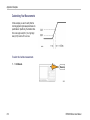
If you are working with static sensitive
components, ground yourself. Static electricity
that builds up on your body can damage
static-sensitive components. Wearing a
grounding strap safely sends static charges on
your body to earth ground.
12
DPO4000 Series User Manual
Installation
To connect the power cord and power on the oscilloscope:
DPO4000 Series User Manual
13
Installation
Powering Off the Oscilloscope
To power off the oscilloscope and remove the power cord:
14
DPO4000 Series User Manual
Installation
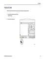
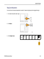
Functional Check
Perform this quick functional check to verify that your oscilloscope is operating correctly.
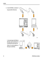
1. Connect the oscilloscope power cable as
described above.
2. Power on the oscilloscope.
DPO4000 Series User Manual
15
Installation
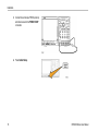
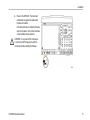
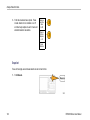
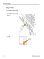
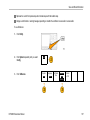
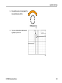
3. Connect the oscilloscope P6139A probe tip
and reference lead to the PROBE COMP
connectors.
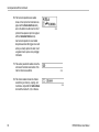
4. Press Default Setup.
16
DPO4000 Series User Manual
Installation
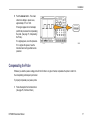
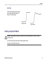
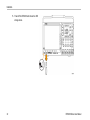
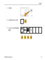
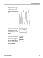
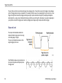
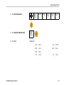
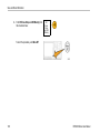
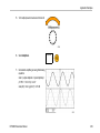
5. Push the Autoset button. The screen
should now display a square wave,
approximately 2.5 V at 1 kHz.
If the signal appears but is misshapen,
perform the procedures for compensating
the probe. (See page 17, Compensating
the Probe.)
If no signal appears, rerun the procedure.
If it no signal still appears, have the
instrument serviced by qualified service
personnel.
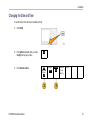
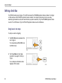
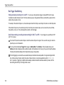
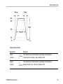
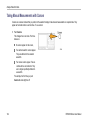
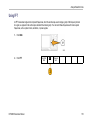
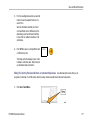
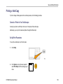
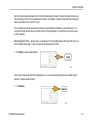
Compensating the Probe
Whenever you attach a passive voltage probe for the first time to any input channel, compensate the probe to match it to
the corresponding oscilloscope input channel.
To properly compensate your passive probe:
1. Follow the steps for the functional check.
(See page 15, Functional Check.)
DPO4000 Series User Manual
17
Installation
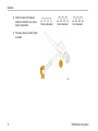
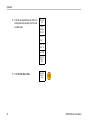
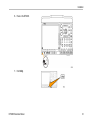
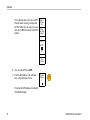
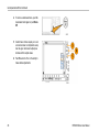
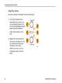
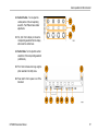
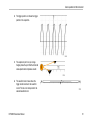
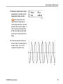
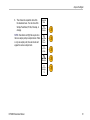
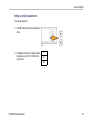
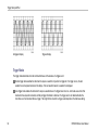
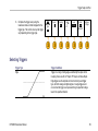
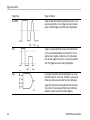
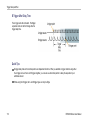
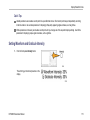
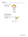
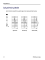
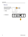
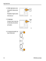
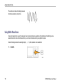
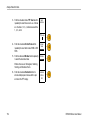
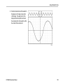
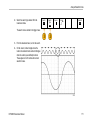
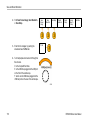
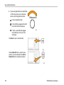
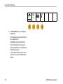
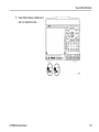
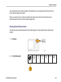
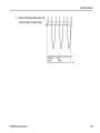
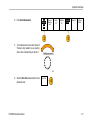
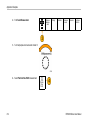
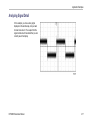
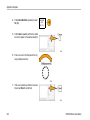
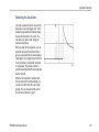
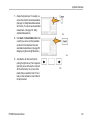
2. Check the shape of the displayed
waveform to determine if your probe is
properly compensated.
Properly compensated
Under compensated
Over compensated
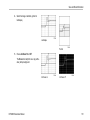
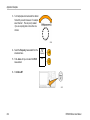
3. If necessary, adjust your probe. Repeat
as needed.
18
DPO4000 Series User Manual
Installation
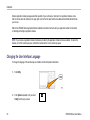
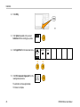
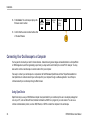
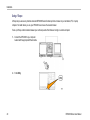
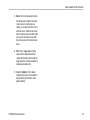
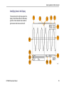
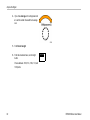
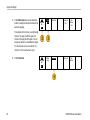
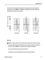
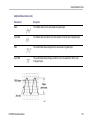
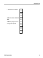
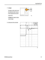
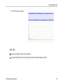
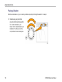
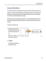
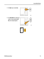
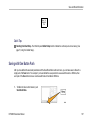
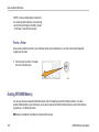
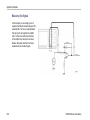
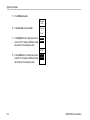
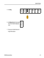
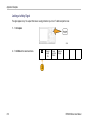
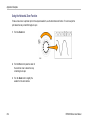
Quick Tips
Use the shortest possible ground lead and signal
path to minimize probe-induced ringing and
distortion on the measured signal.
Short ground lead
Long ground lead
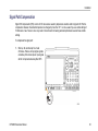
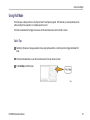
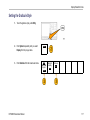
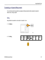
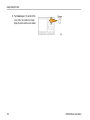
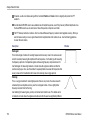
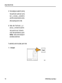
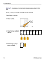
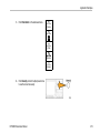
Installing an Application Module
CAUTION. To avoid damage to the oscilloscope or application module, observe ESD precautions. (See page 11, Powering
On the Oscilloscope.)
Turn off the oscilloscope power while removing or adding an application module.
(See page 14, Powering Off the Oscilloscope.)
DPO4000 Series User Manual
19
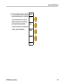
Installation
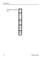
Optional application module packages extend the capability of your oscilloscope. Install up to four application modules at one
time into the two slots with windows in the upper right corner of the front panel and the two additional slots hidden behind the two
you can see.
Refer to the DPO4000 Series Application Module Installation Instructions that came with your application module for instructions
on installing and testing an application module.
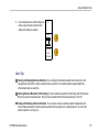
NOTE. If you remove an application module, the features provided by the application module become unavailable. To restore the
features, turn off the oscilloscope power, reinstall the module and turn on the oscilloscope power.
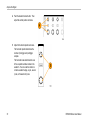
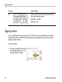
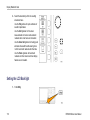
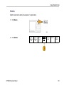
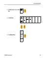
Changing the User Interface Language
To change the language of the oscilloscope user interface and the front-panel button labels:
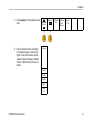
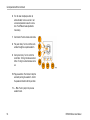
1. Push Utility.
2. Push System repeatedly until you select
Config from the pop-up menu.
20
Config
DPO4000 Series User Manual
Installation
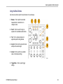
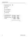
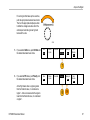
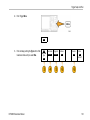
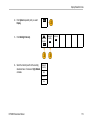
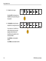
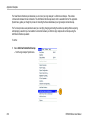
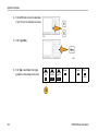
3. Push Language from the resulting lower-bezel
menu.
4. Push the side-bezel button corresponding
to the desired language. Choose among:
English, French, Italian, German, Spanish,
Japanese, Brazilian Portuguese, Simplified
Chinese, Traditional Chinese, Korean, and
Russian.
System
Config
Language
English
Set Date &
Time
TekSecure
Erase
Memory
Version
v1.00
Language
English
Francais
Deutsch
Italiano
-more1 of 3
DPO4000 Series User Manual
21
Installation
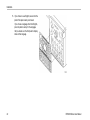
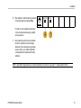
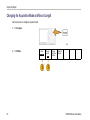
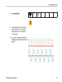
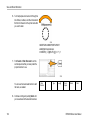
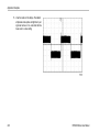
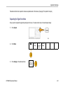
5. If you choose to use English, be sure that the
plastic front-panel overlay is removed.
If you choose a language other than English,
place the plastic overlay for the language
that you desire over the front panel to display
labels in that language.
22
DPO4000 Series User Manual
Installation
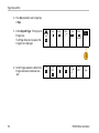
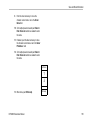
Changing the Date and Time
To set the internal clock with the current date and time:
1. Push Utility.
2. Push System repeatedly until you select
Config from the pop-up menu.
Config
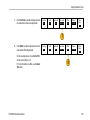
3. Push Set Date & Time.
System
Config
DPO4000 Series User Manual
Language
English
Set Date &
Time
TekSecure
Erase
Memory
Version
23
Installation
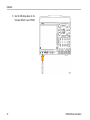
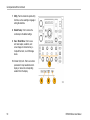
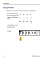
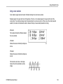
4. Push the side-panel buttons and rotate both
multipurpose knobs (a and b) to set the time
and date values.
Date Time
Set
Display
Date/Time
ON OFF
Hour: 4
Min: 1
Month: July
Day: 19
Year: 2005
OK Enter
Date &
Time
5. Push OK Enter Date & Time.
24
OK Enter
Date &
Time
DPO4000 Series User Manual
Installation
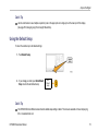
Signal Path Compensation
Signal Path Compensation (SPC) corrects for DC inaccuracies caused by temperature variations and/or long-term drift. Run the
compensation whenever the ambient temperature has changed by more than 10 °C or once a week if you use vertical settings of
5 mV/division or less. Failure to do so may result in the instrument not meeting warranted performance levels at those volts/div
settings.
To compensate the signal path:
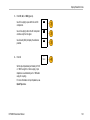
1. Warm up the oscilloscope for at least
20 minutes. Remove all input signals (probes
and cables) from channel inputs. Input signals
with AC components adversely affect SPC.
DPO4000 Series User Manual
25
Installation
2. Push Utility.
3. Push System repeatedly until you select
Calibration from the resulting pop-up menu.
Calibration
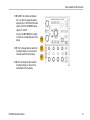
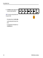
4. Push Signal Path from the lower-bezel menu.
System
Calibration
5. Push OK Compensate Signal path from the
resulting side-bezel menu.
Signal Path
Pass
Factory
Pass
OK Compensate
Signal Path
The calibration will take approximately
10 minutes to complete.
26
DPO4000 Series User Manual
Installation
6. After calibration, verify that the status indicator
on the lower-bezel menu displays Pass.
System
Calibration
Signal Path
Pass
Factory
Pass
If it does not, then recalibrate the instrument
or have the instrument serviced by qualified
service personnel.
7. Service personnel use the factory calibration
functions to calibrate the internal voltage
references of the oscilloscope using external
sources. Refer to your Tektronix field office
or representative for assistance with factory
calibration.
NOTE. Signal Path Compensation does not include calibration to the probe tip. (See page 17, Compensating the Probe.)
DPO4000 Series User Manual
27
Installation
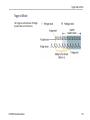
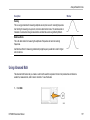
Upgrading Firmware
To upgrade the firmware of the oscilloscope:
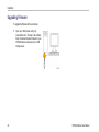
1. Open up a Web browser and go to
www.tektronix.com. Proceed to the software
finder. Download the latest firmware for your
DPO4000 series oscilloscope onto a USB
storage device.
28
DPO4000 Series User Manual
Installation
2. Power off your DPO4000.
DPO4000 Series User Manual
29
Installation
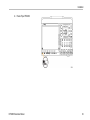
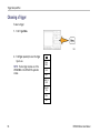
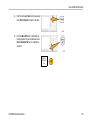
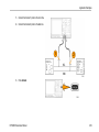
3. Insert the USB storage device into the
front-panel USB port on your DPO4000.
30
DPO4000 Series User Manual
Installation
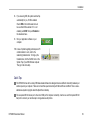
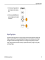
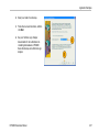
4. Power on the DPO4000. The instrument
automatically recognizes the replacement
firmware and installs it.
If the instrument does not install the firmware,
rerun the procedure. It the problem continues,
contact qualified service personnel.
CAUTION. Do not power off the oscilloscope
or remove the USB storage device until the
oscilloscope finishes installing the firmware.
DPO4000 Series User Manual
31
Installation
5. Power off the DPO4000 and remove the USB
storage device.
32
DPO4000 Series User Manual
Installation
6. Power on the DPO4000.
7. Push Utility.
DPO4000 Series User Manual
33
Installation
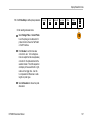
8. Push Version. The oscilloscope displays the
firmware version number.
System
Config
Language
English
Set Date &
Time
TekSecure
Erase
Memory
Version
9. Confirm that the version number matches that
of the new firmware.
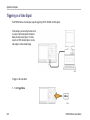
Connecting Your Oscilloscope to a Computer
You may want to document your work for future reference. Instead of saving screen images and waveform data to a CompactFlash
or USB storage device, and then generating a report later, you may want to send it directly to a remote PC for analysis. You may
also want to control an oscilloscope at a remote location from your computer.
Two ways to connect your oscilloscope to a computer are the TekVISA-based OpenChoice and the e*Scope Web-enabled tool.
Use OpenChoice to communicate with your oscilloscope from your computer through a software application. Use e*Scope to
communicate with your oscilloscope through a Web browser.
Using OpenChoice
OpenChoice lets you use your MS-Windows computer to acquire data from your oscilloscope for use in an analysis package that
runs on your PC, such as Microsoft Excel, National Instruments LabVIEW. or a program of your own creation. You can use a
common communications protocol, such as USB, Ethernet, or GPIB to connect the computer to the oscilloscope.
34
DPO4000 Series User Manual
Installation
To set up OpenChoice communications between your oscilloscope and a computer:
1. Load the TekVISA drivers on your computer.
Find these on the OpenChoice Desktop
CD or at the Tektronix software finder Web
page (www.tektronix.com). When done, the
TekVISA icon appears in the Windows System
Tray. Typically, this is the bottom right of
the Windows desktop on your MS-Windows
computer.
DPO4000 Series User Manual
35
Installation
2. Connect the DPO4000 to your computer with
the appropriate USB or Ethernet cable.
To communicate between the DPO4000 and a
GPIB system, connect the oscilloscope to the
TEK-USB-488 GPIB-to-USB Adapter with a
USB cable. Then connect the adapter to your
GPIB system with a GPIB cable.
36
DPO4000 Series User Manual
Installation
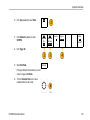
3. Push Utility.
4. Push System repeatedly to select I/O.
5. To use Ethernet, push Ethernet Network
Settings.
DPO4000 Series User Manual
I/O
System
I/O
USB
Enabled
Ethernet
Network
Settings
GPIB
1
37
Installation
On the side-bezel menu, if you are on a DHCP
Ethernet network and using a through cable,
set DHCP to On. If you are using a cross-over
cable, set it to Off and set a hard coded TCPIP
address.
Network
Configuration
Change
Instrument
Settings
DHCP/
BOOTP
On
Off
Test
Connection
6. If you are using GPIB, push GPIB.
7. Enter the GPIB address on the side-bezel
menu, using multipurpose knob a.
Talk/Listen
Address
a
1
This will set the GPIB address on an attached
TEK-USB-488 Adapter.
38
DPO4000 Series User Manual
Installation
8. If you are using USB, the system sets itself up
automatically for you, if USB is enabled.
Check USB on the bottom-bezel menu to
be sure that USB is enabled. If it is not
enabled, push USB. Then push Enabled on
the side-bezel menu.
9. Run your application software on your
computer.
10. In case of problems getting oscilloscope-to-PC
communications to work, refer to the
networking troubleshooter. To bring up the
troubleshooter, click the TekVISA icon on the
System Tray of your MS-Windows computer.
Then go to the online help.
Quick Tips
The DPO4000 comes with a variety of Windows-based software tools designed to ensure efficient connectivity between your
oscilloscope and your computer. There are tool bars that speed connectivity with Microsoft Excel and Word. There is also a
standalone acquisition program called the OpenChoice Desktop.
The rear-panel USB 2.0 device port is the correct USB port for computer connectivity. Use the rear- and front-panel USB 2.0
host ports to connect your oscilloscope to storage devices and printers.
DPO4000 Series User Manual
39
Installation
Using e*Scope
e*Scope lets you access any Internet-connected DPO4000 Series Oscilloscope from a browser on your workstation, PC, or laptop
computer. No matter where you are, your DPO4000 is as close as the nearest browser.
To set up e*Scope communications between your oscilloscope and a Web browser running on a remote computer:
1. Connect the DPO4000 to your computer
network with the appropriate Ethernet cable.
2. Push Utility.
40
DPO4000 Series User Manual
Installation
3. Push System repeatedly to select I/O.
I/O
4. Push Ethernet Network Settings.
USB
System
I/O
DPO4000 Series User Manual
Ethernet
Network
Settings
GPIB
41
Installation
Network
Configuration
5. Push Change Instrument Settings to
determine the Ethernet address and
instrument name.
On the side-bezel menu, if you are on a
DHCP Ethernet network and using dynamic
addressing, set DHCP to On. If you are using
static addressing, set it to Off.
Change
Instrument
Settings
DHCP/
BOOTP
On Off
Test
Connection
6. Start your browser on your remote computer.
In the browser address line, enter the IP
address or, if DHCP is set to On in the
oscilloscope, simply enter the instrument
name.
42
DPO4000 Series User Manual
Installation
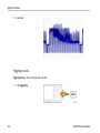
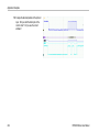
7. You should now see the e*Scope screen, with
a copy of the oscilloscope display, on your
Web browser.
If e*Scope does not work, rerun the procedure.
If it still does not work, contact qualified service
personnel.
DPO4000 Series User Manual
43
Installation
44
DPO4000 Series User Manual
Get Acquainted with the Instrument
Get Acquainted with the Instrument
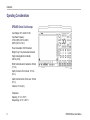
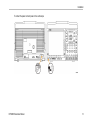
Front-Panel Menus and Controls
The front panel has buttons and controls for the functions that you use most often. Use the menu buttons to access more
specialized functions.
DPO4000 Series User Manual
45
Get Acquainted with the Instrument
Using the Menu System
To use the menu system:
1. Push a front-panel menu button to display
the menu that you want to use.
46
DPO4000 Series User Manual
Get Acquainted with the Instrument
2. Push a lower-bezel button to select a menu
item. If a pop-up menu appears, push the
lower-bezel button repeatedly to select the
desired choice.
3. Push a side-bezel button to choose a
side-bezel menu item.
If the menu item contains more than
one choice, push the side-bezel button
repeatedly to cycle through the choices.
DPO4000 Series User Manual
47
Get Acquainted with the Instrument
4. To remove a side-bezel menu, push the
lower-bezel button again or push Menu
Off.
5. Certain menu choices require you to set
a numerical value to complete the setup.
Use the upper and lower multipurpose
knobs a and b to adjust values.
6. Push Fine to turn off or on the ability to
make smaller adjustments.
48
DPO4000 Series User Manual
Get Acquainted with the Instrument
Using the Menu Buttons
Use the menu buttons to perform many functions in the oscilloscope.
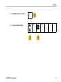
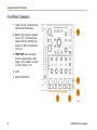
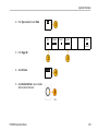
1. Measure. Push to perform automated
measurements on waveforms or to
configure cursors.
2. Search. Push to search through an
acquisition for user-defined events/criteria.
3. Test. Push to activate advanced or
application-specific testing features.
4. Acquire. Push to set the acquisition mode
and adjust the record length.
5. Autoset. Push to perform an automatic
setup of oscilloscope settings.
6. Trigger Menu. Push to specify trigger
settings.
DPO4000 Series User Manual
49
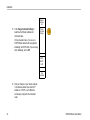
Get Acquainted with the Instrument
7. Utility. Push to activate the system utility
functions, such as selecting a language or
setting the date/time.
8. Default Setup. Push to restore the
oscilloscope to the default settings.
9. Save / Recall Menu. Push to save
and recall setups, waveforms, and
screen images to internal memory, a
CompactFlash card, or a USB storage
device.
10. Channel 1,2,3, or 4. Push to set vertical
parameters for input waveforms and to
display or remove the corresponding
waveform from the display.
50
DPO4000 Series User Manual
Get Acquainted with the Instrument
11. B1 or B2. Push to define and display a
bus, if you have the appropriate module
application keys. The DPO4AUTO module
supports CAN. The DPO4EMBD module
supports I2C and SPI.
Also, push the B1 or B2 button to display
or remove the corresponding bus from the
display.
12. R. Push to manage reference waveforms,
including the display or removal of each
reference waveform from the display.
13. M. Push to manage the math waveform,
including the display or removal of the
math waveform from the display.
DPO4000 Series User Manual
51
Get Acquainted with the Instrument
Using Other Controls
These buttons and knobs control waveforms, cursors and other data input.
1. Turn the upper multipurpose knob a,
when activated, to move a cursor or set
a numerical parameter value for a menu
item. Push the nearby Fine button to toggle
between coarse and fine adjustment.
Screen icons tell you when a or b are
active.
2. Cursors. Push once to activate the two
vertical cursors. Push again to turn on the
two vertical and two horizontal cursors.
Push again to turn off all cursors.
When the cursors are on, you can turn
the multipurpose knobs to control their
position.
52
DPO4000 Series User Manual
Get Acquainted with the Instrument
3. Select. Push to activate special functions.
For example, when using the two vertical
cursors (and no horizontal ones are
visible), you can push this button to link or
unlink the cursors. When the two vertical
and two horizontal cursors are both visible,
you can push this button to make either
the vertical cursors or the horizontal ones
active.
4. Fine. Push to toggle between making
coarse and fine adjustments with the
vertical and horizontal position knobs, the
trigger level knob, and many operations of
multipurpose knobs a and b.
5. Waveform Intensity. Push to enable
multipurpose knob a to control waveform
display intensity and knob b to control
graticule intensity.
DPO4000 Series User Manual
53
Get Acquainted with the Instrument
6. Turn the lower multipurpose knob b,
when activated, to move a cursor or set
a numerical parameter value for a menu
item. Push Fine to make adjustments
more slowly.
7. Zoom button. Push to activate zoom mode.
8. Pan (outer knob). Turn to scroll the zoom
window through the acquired waveform.
9. Zoom (inner knob). Turn to control the
zoom factor. Turning it clockwise zooms in
further. Turning it counterclockwise zooms
out.
10. Play-pause button. Push to start or stop the
automatic panning of a waveform. Control
the speed and direction with the pan knob.
11. ← Prev. Push to jump to the previous
waveform mark.
54
DPO4000 Series User Manual
Get Acquainted with the Instrument
12. Set/Clear Mark. Push to establish or
delete a waveform mark.
13. → Next. Push to jump to the next
waveform mark.
14. Horizontal Position. Turn to adjust
the trigger point location relative to the
acquired waveforms. Push Fine to make
smaller adjustments.
15. Horizontal Scale. Turn to adjust the
horizontal scale (time/division).
DPO4000 Series User Manual
55
Get Acquainted with the Instrument
16. Run/Stop. Push to start or stop
acquisitions.
17. Single. Push to make a single acquisition.
18. Autoset. Push to automatically set the
vertical, horizontal, and trigger controls for
a usable, stable display.
19. Trigger Level. Turn to adjust the trigger
level.
20. Set to 50%. Push to set the trigger level to
the midpoint of the waveform.
21. Force Trig. Push to force an immediate
trigger event.
56
DPO4000 Series User Manual
Get Acquainted with the Instrument
22. Vertical Position. Turn to adjust the
vertical position of the corresponding
waveform. Push Fine to make smaller
adjustments.
23. 1, 2, 3, 4. Push to display or remove the
corresponding waveform from the display
and access the vertical menu.
24. Vertical Scale. Turn to adjust the vertical
scale factor of the corresponding waveform
(volts/division).
25. Print. Push to initiate a hard copy using the
printer selected in the Utility menu.
26. Power switch. Push to power on or off the
instrument.
DPO4000 Series User Manual
57
Get Acquainted with the Instrument
27. USB 2.0 host port. Insert a USB cable here
to connect peripherals, such as printers
and storage devices, to the oscilloscope.
There are also two more USB 2.0 host
ports on the rear panel.
28. CompactFlash Drive. Insert a
CompactFlash card here.
29. CompactFlash Eject. Pops the
CompactFlash card out of the
CompactFlash drive.
30. Save. Push to perform an immediate save
operation. The save operation uses the
current save parameters, as defined in the
Save / Recall menu.
31. Default Setup. Push to perform an
immediate restore of the oscilloscope to
the default settings.
32. Menu Off. Push to clear a displayed menu
from the screen.
58
DPO4000 Series User Manual
Get Acquainted with the Instrument
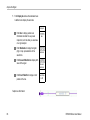
Identifying Items in the Display
The items shown to the right may appear in the
display. Not all of these items are visible at any
given time. Some readouts move outside the
graticule area when menus are turned off.
DPO4000 Series User Manual
59
Get Acquainted with the Instrument
1. The acquisition readout shows when an
acquisition is running, stopped, or when
acquisition preview is in effect. Icons are:
RUN
Run: Acquisitions enabled
Stop: Acquisitions not enabled
Roll: In roll mode (40 ms/div or slower)
PreVu: In this state, the oscilloscope
is stopped or between triggers. You
can change the horizontal or vertical
position or scale to see approximately
what the next acquisition will look like.
60
DPO4000 Series User Manual
Get Acquainted with the Instrument
2. The trigger position icon shows the trigger
position in the acquisition.
3. The expansion point icon (an orange
triangle) shows the point that the horizontal
scale expands and compresses around.
4. The waveform record view shows the
trigger location relative to the waveform
record. The line color corresponds to the
selected waveform color.
DPO4000 Series User Manual
61
Get Acquainted with the Instrument
5. The trigger status readout shows trigger
status. Status conditions are:
Trig’d
Trig’d: Triggered
Auto: Acquiring untriggered signal
PrTrig: Acquiring pretrigger data
Trig?: Waiting for trigger
6. The cursor readout shows time, amplitude,
and delta (∆) values for each cursor.
For FFT measurements, it shows frequency
and magnitude.
62
DPO4000 Series User Manual
Get Acquainted with the Instrument
7. The trigger level icon shows the trigger
level on the waveform. The icon color
corresponds to the trigger source channel
color.
8. The edge trigger readout shows the trigger
source, slope, and level. The trigger
readouts for other trigger types show other
parameters.
9. The top line of the record length/sampling
rate readout shows the sampling rate
(adjust with the Horizontal Scale knob).
The bottom line shows the record length
(adjust with the Acquire menu).
DPO4000 Series User Manual
63
Get Acquainted with the Instrument
10. The horizontal position/scale readout
shows on the top line the horizontal scale
(adjust with the Horizontal Scale knob)
and on the bottom line the time from the T
symbol to the expansion point icon (adjust
with the Horizontal Position knob).
Use horizontal position to insert added
delay between when the trigger occurs and
when you actually capture the data. Insert
a negative time to capture more pretrigger
information.
11. The auxiliary waveform readouts show the
vertical and horizontal scale factors of the
math or reference waveforms.
12. The channel readout shows the channel
scale factor (per division), coupling, and
invert status. Adjust with the Vertical Scale
knob and the channel 1, 2, 3, or 4 menus.
64
DPO4000 Series User Manual
Get Acquainted with the Instrument
13. Measurement readouts show the selected
measurements. You can select up to four
measurements to display at one time.
A
symbol appears instead of the
expected numerical measurement if a
vertical clipping condition exists. Part of the
waveform is above or below the display. To
obtain a proper numerical measurement,
turn the vertical scale and position knobs
to make all of the waveform appear in the
display.
14. The waveform baseline indicator shows
the zero-volt level of a waveform (ignoring
the effect of offset). The icon colors
correspond to the waveform colors.
DPO4000 Series User Manual
65
Get Acquainted with the Instrument
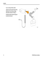
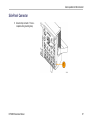
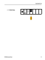
Front-Panel Connectors
1. Channel 1, 2, (3, 4). Channel inputs with
TekVPI Versatile Probe Interface.
2. Aux In. Trigger level range is adjustable
from +8 V to –8 V. The maximum input
voltage is 400V peak, 250V RMS. Input
resistance is 1 MΩ ± 1% in parallel with
13 pF ±2 pF.
3. PROBE COMP. Square wave signal
source to compensate probes. Output
voltage: 0 – 2.5V, amplitude ± 1% behind
1k Ω ±2%. Frequency: 1 kHz.
4. Ground.
5. Application Module Slots.
66
DPO4000 Series User Manual
Get Acquainted with the Instrument
Side-Panel Connector
1. Ground strap connector. This is a
receptacle for a grounding strap.
DPO4000 Series User Manual
67
Get Acquainted with the Instrument
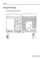
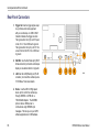
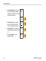
Rear-Panel Connectors
1. Trigger Out. Use the trigger signal output
to synchronize other test equipment
with your oscilloscope. A LOW to HIGH
transition indicates the trigger occurred.
The logic level for Vout (HI) is ≥2.5V open
circuit; ≥1.0 V into a 50Ω load to ground.
The logic level for Vout (LO) is ≤0.7 V into
a load of ≤4 mA; ≤0.25 V into a 50Ω load
to ground.
2. XGA Out. Use the XGA Video port (DB-15
female connector) to show the oscilloscope
display on an external monitor or projector.
3. LAN. Use the LAN (Ethernet) port (RJ-45
connector) to connect the oscilloscope to a
10/100 Base-T local area network.
4. Device. Use the USB 2.0 High speed
device port to control the oscilloscope
through USBTMC or GPIB with a
TEK-USB-488 Adapter. The USBTMC
protocol allows USB devices to
communicate using IEEE488 style
messages. This lets you run your GPIB
software applications on USB hardware.
68
DPO4000 Series User Manual
Get Acquainted with the Instrument
5. Host. Use the USB 2.0 Full speed host
ports (two) to take advantage of USB mass
storage devices and printers.
6. Power input. Attach to an AC power line
with integral safety ground. (See page 6,
Operating Considerations.)
DPO4000 Series User Manual
69
Acquire the Signal
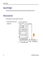
Acquire the Signal
This section describes concepts of and procedures for setting up the oscilloscope to acquire the signal as you want it to.
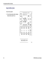
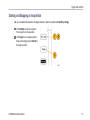
Setting Up Signal Input
Use front-panel buttons to set up your instrument to acquire the signal.
1. Connect the P6139A or VPI probe to the
input signal source.
70
DPO4000 Series User Manual
Acquire the Signal
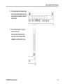
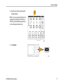
2. Select the input channel by pushing the
front-panel buttons.
NOTE. If you are using a probe that does not
supply probe encoding (not a P6139A nor a
VPI probe), set the attenuation (probe factor)
on the oscilloscope side-bezel menu.
3. Push Autoset.
DPO4000 Series User Manual
71
Acquire the Signal
4. Push the desired channel button. Then
adjust the vertical position and scale.
5. Adjust the horizontal position and scale.
The horizontal position determines the
number of pretrigger and posttrigger
samples.
The horizontal scale determines the size
of the acquisition window relative to the
waveform. You can scale the window to
contain a waveform edge, a cycle, several
cycles, or thousands of cycles.
72
DPO4000 Series User Manual
Acquire the Signal
Quick Tip
Use the zoom feature to see multiple acquisition cycles in the upper part and a single cycle in the lower part of the display.
(See page 163, Managing Long Record Length Waveforms.)
Using the Default Setup
To return the oscilloscope to its default settings:
1. Push Default Setup.
2. If you change your mind, push Undo Default
Setup to undo the last default setup.
Undo
Default
Setup
Quick Tip
The DPO4000 Technical Reference describes the default setup settings in detail. This manual is available on the accompanying
CD or at www.tektronix.com.
DPO4000 Series User Manual
73
Acquire the Signal
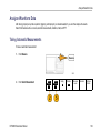
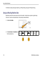
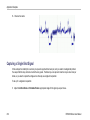
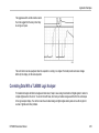
Using Autoset
Autoset adjusts the instrument (acquisition, horizontal, trigger, and vertical controls) such that it displays two or three waveform
cycles with the trigger near the midlevel.
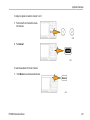
1. Connect the probe, and then select the input
channel. (See page 70, Setting Up Signal
Input.)
2. Push Autoset to execute an Autoset.
3. If desired, push Autoset Undo to undo the
last Autoset.
74
Undo
Autoset
DPO4000 Series User Manual
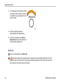
Acquire the Signal
Quick Tips
To position the waveform appropriately, Autoset may change the vertical position. Autoset always sets vertical offset to 0 V.
If you use Autoset when no channels are displayed, the instrument turns on channel one (1) and scales it.
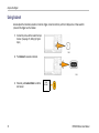
Acquisition Concepts
Before a signal can be displayed, it must pass through the input channel where it is scaled and digitized. Each channel has a
dedicated input amplifier and digitizer. Each channel produces a stream of digital data from which the instrument extracts waveform
records.
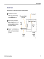
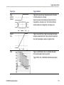
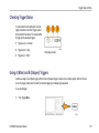
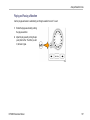
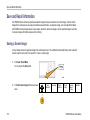
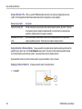
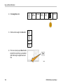
Sampling Process
Acquisition is the process of sampling an
analog signal, converting it into digital data,
and assembling it into a waveform record,
which is then stored in acquisition memory.
DPO4000 Series User Manual
Input signal
Sampled points
Digital values
75
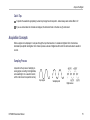
Acquire the Signal
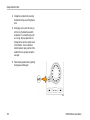
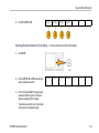
Real-time Sampling
DPO4000 series oscilloscopes use real-time
sampling. In real-time sampling, the instrument
digitizes all of the points it acquires using a
single trigger event.
Record points
Sampling rate
76
DPO4000 Series User Manual
Acquire the Signal
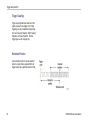
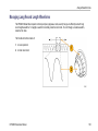
Waveform Record
The instrument builds the waveform record through use of the following parameters:
Sample interval: The time between
recorded sample points. Adjust this by
turning the Horizontal Scale knob.
Record length: The number of samples
required to fill a waveform record. Set this
by pushing the Acquire button and using
the resulting lower-bezel menu.
Trigger point: The zero time reference in a
waveform record. It is shown on the screen
by an orange T.
DPO4000 Series User Manual
77
Acquire the Signal
Horizontal position: The time from the
trigger point to the expansion point. Adjust
this by turning the Horizontal Position
knob.
Use a positive time to acquire the record
after the trigger point. Use a negative time
to acquire it before the trigger point.
Expansion point: The point that the
horizontal scale expands and contracts
around. It is shown by an orange triangle.
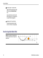
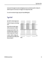
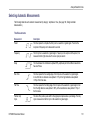
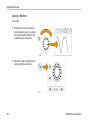
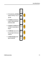
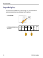
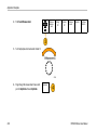
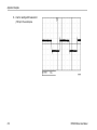
How the Acquisition Modes Work
Sample mode retains the first sampled point
from each acquisition interval. Sample is the
default mode.
78
DPO4000 Series User Manual
Acquire the Signal
Peak Detect mode uses the highest and lowest
of all the samples contained in two consecutive
acquisition intervals. This mode only works
with real-time, noninterpolated sampling and is
useful for catching high frequency glitches.
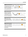
Hi Res mode calculates the average of all
the samples for each acquisition interval.
This mode also only works with real-time,
noninterpolated sampling. Hi-Res provides a
higher-resolution, lower-bandwidth waveform.
Envelope mode finds the highest and
lowest record points over all acquisitions.
Envelope uses Peak Detect for each individual
acquisition.
Average mode calculates the average value for
each record point over a user-specified number
of acquisitions. Average uses Sample mode for
each individual acquisition. Use average mode
to reduce random noise.
DPO4000 Series User Manual
79
Acquire the Signal
Changing the Acquisition Mode and Record Length
Use this procedure to change the acquisition mode.
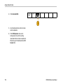
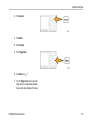
1. Push Acquire.
2. Push Mode.
80
Mode
Average
Record
Length
10k
Reset
Horizontal
Position
Waveform
Display
DPO4000 Series User Manual
Acquire the Signal
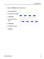
3. Then choose the acquisition mode from
the side-bezel menu. You can chose from:
Sample, Peak Detect, Hi Res, Envelope, or
Average.
NOTE. Peak Detect and High Res require more
than one sample point per sample interval. If there
is only one sample point, these two modes will
appear the same as sample mode.
Acquisition
Mode
Sample
Peak
Detect
Hi Res
Envelope
Average
16
DPO4000 Series User Manual
81
Acquire the Signal
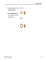
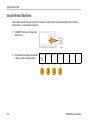
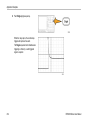
4. If you chose Average, turn multipurpose knob
a to set the number of waveforms to average
over.
5. Push Record Length.
6. Push the side-bezel menu, record length
button.
1000 points
Choose between: 1000, 10 k, 100 k, 1 M, and
10 M points.
82
DPO4000 Series User Manual
Acquire the Signal
Using Roll Mode
Roll mode gives a display similar to a strip chart recorder for low-frequency signals. Roll mode lets you see acquired data points
without waiting for the acquisition of a complete waveform record.
Roll mode is enabled when the trigger mode is auto and the horizontal scale is set to 40 ms/div or slower.
Quick Tips
Switching to Envelope or Average acquisition mode, using math waveforms, or switching to normal trigger will disable Roll
mode.
Roll mode is disabled when you set the horizontal scale to 20 ms per division or faster.
Push Run/Stop to halt Roll mode.
DPO4000 Series User Manual
83
Acquire the Signal
Defining a Serial Bus
Your DPO4000 oscilloscope can trigger on I2C and SPI serial buses if the DPO4EMBD application module is installed. It can trigger
on CAN serial buses if the DPO4AUTO application module is installed. It can display the physical layer of a bus (as analog
waveforms), digital waveforms, and protocol level information (as symbolic waveforms). Plug in the DPO4EMBD application module
to use the I2C and SPI features. Plug in the DPO4AUTO application module to use the CAN features.
Using buses in two steps
To quickly use serial bus triggering:
1. Push B1 or B2 and enter parameters of the
bus to trigger on.
You can separately use B1 and B2 to view
two different buses.
2. Push Trigger Menu and enter trigger
parameters. (See page 98, Choosing a
Trigger.)
You can display bus information without
triggering on the bus signal.
84
DPO4000 Series User Manual
Acquire the Signal
Setting up serial bus parameters
To set up bus parameters:
1. Push B1 or B2 to bring up the lower-bezel bus
menu.
2. Push Bus as many times as needed to select
the desired bus (I2C, SPI, or CAN) from the
pop-up menu.
DPO4000 Series User Manual
I2C
SPI
CAN
85
Acquire the Signal
3. Push Define Inputs and use the side-bezel
buttons to assign oscilloscope channels to the
serial bus signal(s).
Bus
I2C
Define
Inputs
Thresholds
Display As
Bus
Bus
Decode
Hex
Define
Inputs
Thresholds
Display As
Bus
Decode
For example, with an I2C bus, you might assign
channel 1 to supply the SCLK signal and
channel 2 to supply the SDA signal. You can
assign any channel to a predefined bus signal.
For all serial bus sources, use channel 1 to
channel 4. Do not use the Aux In input.
4. Push Thresholds.
Bus
I2C
86
DPO4000 Series User Manual
Acquire the Signal
For each signal that makes up the serial bus,
push the appropriate side-bezel menu button.
Then turn the appropriate multipurpose knob
to define the voltage level above which the
oscilloscope treats the signal as high and
below which as low.
5. If you selected CAN above, push Bit Rate and
the desired side-bezel menu choice.
Bus
CAN
Define
Inputs
Thresholds
Bit Rate
500 Kbps
Display As
Bus
Bus
Decode
Hex
6. If you selected SPI above, push Polarity and
the desired side-bezel menu choice.
Bus
SPI
Define
Inputs
Thresholds
Polarity
Display As
Bus
Bus
Decode
Hex
Active High means when a signal is greater
than the threshold value, it is considered a
logical 1. Active Low means when the signal is
lower than the threshold value, it is considered
a logical 1.
DPO4000 Series User Manual
87
Acquire the Signal
7. Push Display As and use the side-bezel menu
to define how to display the serial bus.
Display As
Push Bus to display packet level
information decoded for easy visual
inspection, much like what you would see
on a logic analyzer.
Push Waveforms to display the digital
(high or low) representations of the
waveforms.
Push Bus and Waveforms to display both
views of the signal.
Push Event Table On to display a list of
packets in the bus.
Bus
Waveforms
Bus and
Waveforms
Event Table
On Off
Sample bus information:
88
DPO4000 Series User Manual
Acquire the Signal
Sample waveforms:
Sample event table:
8. Push Bus Decode and the desired side-bezel
menu choice to display the bus data in
hexadecimal or binary format.
9. Turn multipurpose knob a to move the bus
display up or down on the screen.
DPO4000 Series User Manual
89
Acquire the Signal
You can also trigger on packet level information on your serial bus. (See page 102, Triggering on Buses.)
NOTE. To acquire signals from two buses simultaneously, use this procedure once to define the parameters of the B1 bus and
again to define the B2 bus.
90
DPO4000 Series User Manual
Trigger Setup and Run
Trigger Setup and Run
This section contains concepts and procedures for setting up the oscilloscope to trigger on your signal.
Triggering Concepts
Trigger Event
The trigger event establishes the time-reference point in the waveform record. All waveform record data is located in time with
respect to that point. The instrument continuously acquires and retains enough sample points to fill the pretrigger portion of the
waveform record. That is the part of the waveform that is displayed before, or to the left of, the triggering event on screen. When a
trigger event occurs, the instrument starts acquiring samples to build the posttrigger portion of the waveform record, that is, the part
displayed after or to the right of the trigger event. After a trigger is recognized, the instrument will not accept another trigger until
the acquisition is complete and the holdoff time has expired.
DPO4000 Series User Manual
91
Trigger Setup and Run
Untriggered display
Triggered display
Trigger Modes
The trigger mode determines how the instrument behaves in the absence of a trigger event:
Normal trigger mode enables the instrument to acquire a waveform only when it is triggered. If no trigger occurs, the last
waveform record acquired remains on the display. If no last waveform exists, no waveform is displayed.
Auto trigger mode enables the instrument to acquire a waveform even if a trigger does not occur. Auto mode uses a timer that
starts when the acquisition is started, and the pretrigger information is obtained. If a trigger event is not detected before the
timer times out, the instrument forces a trigger. The length of time it waits for a trigger event depends on the time base setting.
92
DPO4000 Series User Manual
Trigger Setup and Run
Auto mode, when forcing triggers in the absence of valid triggering events, does not synchronize the waveform on the display. The
waveform will appear to roll across the screen. If valid triggers occur, the display will become stable.
You can also force the instrument to trigger by pushing the front-panel Force Trig button.
Trigger Holdoff
Adjust holdoff to obtain stable triggering when
the instrument is triggering on undesired trigger
events.
Trigger holdoff can help stabilize triggering,
since the oscilloscope does not recognize
new triggers during the holdoff time. When
the instrument recognizes a trigger event, it
disables the trigger system until acquisition
is complete. In addition, the trigger system
remains disabled during the holdoff period that
follows each acquisition.
DPO4000 Series User Manual
Holdoffs
93
Trigger Setup and Run
Trigger Coupling
Trigger coupling determines what part of the
signal is passed to the trigger circuit. Edge
triggering can use all available coupling types:
DC, Low Frequency Rejection, High Frequency
Rejection, and Noise Rejection. All other
trigger types use DC coupling only.
Horizontal Position
Use horizontal position to acquire waveform
detail in a region that is separated from the
trigger location by a significant interval of time.
94
DPO4000 Series User Manual
Trigger Setup and Run
1. Adjust the position (delay) time by rotating
the Horizontal Position knob.
2. Turn horizontal SCALE to acquire the
detail that you need around the position
(delay) expansion point.
DPO4000 Series User Manual
95
Trigger Setup and Run
The part of the record that occurs before the trigger is the pretrigger portion. The part that occurs after the trigger is the posttrigger
portion. Pretrigger data can help you troubleshoot. For example, to find the cause of an unwanted glitch in your test circuit, you can
trigger on the glitch and make the pretrigger period large enough to capture data before the glitch. By analyzing what happens
before the glitch, you may uncover information that helps you find the source of the glitch. Alternatively, to see what is happening in
your system as a result of the trigger event, make the posttrigger period large enough to capture data after the trigger.
Slope and Level
The slope control determines whether the
instrument finds the trigger point on the rising
or the falling edge of a signal.
The level control determines where on that
edge the trigger point occurs.
The DPO4000 provides a long horizontal bar or
bars across the graticule to temporarily show
the trigger level.
96
DPO4000 Series User Manual
Trigger Setup and Run
1. Turn the front-panel Trigger Level knob to
adjust the trigger level without going to a
menu.
2. Push the front-panel Set to 50% button to
quickly set the trigger level to the midpoint
of the waveform.
Delayed Trigger System
Trigger with the A (Main) trigger system alone or, if using an edge trigger, combine the A (Main) trigger with the B (Delayed) trigger
to trigger on sequential events. When using sequential triggering, the A trigger event arms the trigger system, and the B trigger
event triggers the instrument when the B trigger conditions are met. A and B triggers can (and typically do) have separate
sources. The B trigger condition can be based on a time delay or a specified number of events. (See page 107, Using A (Main)
and B (Delayed) Triggers.)
DPO4000 Series User Manual
97
Trigger Setup and Run
Choosing a Trigger
To select a trigger:
1. Push Trigger Menu.
2. Push Type repeatedly to select the trigger
type to use.
NOTE. The bus trigger requires use of the
DPO4EMBD or the DPO4AUTO application
module.
Edge
Pulse
Width
Runt
Logic
Setup &
Hold
Rise/Fall
Time
Video
Bus
98
DPO4000 Series User Manual
Trigger Setup and Run
3. Complete the trigger setup using the
lower-bezel menu controls displayed for the
trigger type. The controls to set up the trigger
vary depending on the trigger type.
Type
Edge
Source
1
Coupling
DC
Slope
Level
100 mV
Mode
Auto
& Holdoff
Configure
B Trigger
Selecting Triggers
Trigger Type
Trigger Conditions
Edge
Trigger on a rising or falling edge, as defined by the slope control.
Coupling choices are DC, LF Reject, HF Reject, and Noise Reject.
Edge triggers are the simplest and most commonly used trigger
type, with both analog and digital signals. An edge trigger event
occurs when the trigger source passes through a specified voltage
level in the specified direction.
DPO4000 Series User Manual
99
Trigger Setup and Run
100
Trigger Type
Trigger Conditions
Pulse/Width
Trigger on pulses that are less than, greater than, equal to, or not
equal to a specified time. You can trigger on positive or negative
pulses. Pulse/width triggers are primarily used on digital signals.
Runt
Trigger on a pulse amplitude that crosses one threshold but fails
to cross a second threshold before recrossing the first. You can
detect positive or negative (or either) runts, or only those wider
than, less than, greater than, equal to, or not equal to a specified
width. Runt triggers are primarily used on digital signals.
Logic
Logic triggers are primarily used with digital signals. You can set
each input to high, low, or don’t care. In addition, you can use one
channel as a clock source set to either the rising or falling edge.
Trigger when logic inputs cause the selected function to become
True or False. You can also specify that the logic conditions be
satisfied for a specific amount of time before triggering.
DPO4000 Series User Manual
Trigger Setup and Run
Trigger Type
Trigger Conditions
Setup
and Hold
Violation
Trigger when a logic data input changes state inside of the setup
or hold time relative to a clock edge.
Setup is the amount of time that data should be stable and not
change before a clock edge occurs. Hold is the time that data
should be stable and not change after a clock edge occurs.
Rise/Fall
Time
Trigger on rise and fall times. Trigger on pulse edges that traverse
between two thresholds at faster or slower rates than the specified
time. Specify pulse edges as positive or negative or either.
Video
Trigger on specified fields or lines of a composite video signal.
Only composite signal formats are supported.
Trigger on NTSC, PAL, or SECAM. Works with Macrovision signals.
DPO4000 Series User Manual
101
Trigger Setup and Run
Trigger Type
Trigger Conditions
Bus
Optional: Trigger on common, serial-bus, packet-level information
with the following application modules:
DPO4EMBD — I2C and SPI
DPO4AUTO — CAN
Triggering on Buses
You can use your DPO4000 oscilloscope to trigger on CAN, I2C, and SPI buses, if you have the DPO4AUTO or the DPO4EMBD
application module installed. The DPO4000 can display both physical layer (as analog waveforms ) and protocol level information
(as digital and symbolic waveforms).
To set up the bus trigger:
1. If you have not already defined your bus using
the front-panel B1 or B2 buttons, do so now.
(See page 84, Defining a Serial Bus.)
102
DPO4000 Series User Manual
Trigger Setup and Run
2. Push Trigger Menu.
Bus
3. Push and keep pushing the Type button of the
lower-bezel menu until you select Bus.
DPO4000 Series User Manual
Type
Bus
Source Bus
B1 (I2C)
Trigger On
Address
Address
07F
Direction
Write
Mode
Auto
& Holdoff
103
Trigger Setup and Run
4. Push and keep pushing the Source Bus
button of the lower-bezel menu until you select
the bus that you want to trigger on.
B1 (I2C)
B2 (I2C)
5. Push and keep pushing the lower-bezel menu
Trigger On button until you select the desired
trigger on feature.
If you are using the I2C bus trigger, you can
trigger on Start, Repeated Start, Stop, Missing
Ack, Address, Data, or Address/Data.
If you are using the SPI bus trigger, you can
trigger on SS Active, MOSI, MISO, or MOSI
& MISO.
If you are using the CAN bus trigger, you can
trigger on Start of Frame, Type of Frame,
Identifier, Data, Id & Data, End of Frame, and
Missing Ack.
104
DPO4000 Series User Manual
Trigger Setup and Run
6. If you are setting up an I2C trigger and have
selected a Trigger On selection of Address
or Address/Data, push the lower-bezel
menu Address button to access the Address
side-bezel menu. Press the side-bezel
menu Address button. Enter the address
parameters of interest with multipurpose knobs
a and b.
Then push the lower-bezel menu Direction
button to enter the direction of interest.
Choices are: Read, Write, and Read or Write.
DPO4000 Series User Manual
105
Trigger Setup and Run
Bus Trigger Data Matching
Rolling window byte matching for I2C and SPI. You can use a rolling window to trigger on data with SPI and I2C buses.
You define the number of bytes to match. Then the oscilloscope uses a rolling window to find any match within a packet, with the
window rolling one byte at a time.
For example, if the number of bytes is one, the oscilloscope will match the first byte, second byte, third, and so on within the packet.
If the number of bytes is two, the oscilloscope will try to match any two consecutive bytes, such as one and two, two and three,
three and four, and so on. If the oscilloscope finds a match, it will then trigger.
Specific byte matching (non-rolling window matching) for CAN, I2C, and SPI. You can trigger on a specific byte for SPI
and I2C in two ways:
For I2C and SPI, enter the number of bytes to match the number of bytes in the signal. Then use don’t cares (X) to mask the
bytes that you are not interested in.
For I2C, push the bottom-bezel Trigger On to trigger on Address/Data. Push Address. On the side-bezel menu, push
Address and rotate multipurpose knobs a and b as needed. Set the address to don’t cares (X) if you want to mask the address.
The data will be matched starting at the first byte without using a rolling window.
For CAN, triggering occurs when the user-selected data input matches the data and qualifier in the signal starting at the first
byte. Set the number of bytes to match the number of bytes of interest. Use the data qualifier to perform: =, !=, <, >, >=,
and <= operations. Triggering on identifier and data always matches the identifier and data selected by the user, with the
data starting at the first byte. No rolling window is used.
106
DPO4000 Series User Manual
Trigger Setup and Run
Checking Trigger Status
To quickly determine the settings of some key
trigger parameters, check the Trigger readout
at the bottom of the display. The readouts differ
for edge and the advanced triggers.
1. Trigger source = channel 1.
2. Trigger slope = rising.
Edge trigger readout
3. Trigger level = 0.00 V.
Using A (Main) and B (Delayed) Triggers
Combine an edge A Event (Main) trigger with the B Event (Delayed) trigger to capture more complex signals. After the A Event
occurs, the trigger system looks for the B Event before triggering and displaying the waveform.
To use the B trigger:
1. Push Trigger Menu.
DPO4000 Series User Manual
107
Trigger Setup and Run
2. Press Type repeatedly to select a trigger type
of Edge.
3. Push Configure B Trigger. This brings up the
B trigger menu.
The B Trigger Setup item only appears if the
A trigger is set to edge trigger.
4. Set the B trigger parameters as defined in the
B trigger lower-bezel and side-bezel menu
items.
108
Type
Edge
B Trigger
On
Source
1
Coupling
DC
Slope
Level
0.00 V
Mode
Auto
& Holdoff
Configure
B Trigger
B Trigger
After A
Time
Source
1
Coupling
DC
Slope
Level
0.00V
Configure
A Trigger
DPO4000 Series User Manual
Trigger Setup and Run
Trigger on B Event
The A trigger arms the instrument. Posttrigger
acquisition starts on the nth B event.
DPO4000 Series User Manual
109
Trigger Setup and Run
B Trigger After Delay Time
The A trigger arms the instrument. Posttrigger
acquisition starts on the first B edge after the
trigger delay time.
Quick Tips
B-trigger delay time and horizontal position are independent functions. When you establish a trigger condition using either
the A trigger alone or the A and B triggers together, you can also use horizontal position to delay the acquisition by an
additional amount.
When using the B trigger, the A and B trigger types can only be Edge.
110
DPO4000 Series User Manual
Trigger Setup and Run
Starting and Stopping an Acquisition
After you have defined the acquisition and trigger parameters, start the acquisition with Run/Stop or Single.
Push Run/Stop to start the acquisition.
Push it again to stop the acquisition.
Push Single to take a single acquisition.
Single sets the trigger mode to Normal for
the single acquisition.
DPO4000 Series User Manual
111
Display Waveform Data
Display Waveform Data
This section contains concepts and procedures for displaying the acquired waveform.
Adding and Removing a Waveform
1. To add or remove an active waveform from
the display, push the relevant front-panel
channel button.
You can use the channel as a trigger
source whether or not it is displayed.
Setting the Display Style and Persistence
1. To set the display style, push Acquire.
112
DPO4000 Series User Manual
Display Waveform Data
2. Push Waveform Display.
DPO4000 Series User Manual
Mode
Sample
Record
Length
10k
Reset
Horizontal
Position
Waveform
Display
113
Display Waveform Data
3. Push Dots Only On Off from the side-bezel
menu. Dots on will display the waveform
record points as dots on the screen. Dots off
connects the dots with vectors.
Waveform
Display
Dots Only
On Off
4. Push Persist Time, and turn multipurpose
knob a to have waveform data remain on
screen for a user-specified amount of time.
114
Persist
Time
a Auto
5. Push Set to Auto to have the oscilloscope
automatically determine a persistence time for
you.
Set to Auto
6. Push Clear Persistence to reset the
persistence information.
Clear Persistence
DPO4000 Series User Manual
Display Waveform Data
Quick Tips
Variable persistence accumulates record points for a specified time interval. Each record point decays independently according
to the time interval. Use variable persistence for displaying infrequently appearing signal anomalies, such as glitches.
Infinite persistence continuously accumulates record points until you change one of the acquisition display settings. Use infinite
persistence for displaying unique signal anomalies, such as glitches.
Setting Waveform and Graticule Intensity
1. Push the front-panel Intensity button.
This will bring up the intensity readout on the
display.
DPO4000 Series User Manual
115
Display Waveform Data
2. Rotate multipurpose knob a to select the
desired waveform intensity.
3. Rotate multipurpose knob b to select the
desired intensity for the graticule and text.
4. Push Intensity again to clear the intensity
readout from the display.
116
DPO4000 Series User Manual
Display Waveform Data
Setting the Graticule Style
1. To set the graticule style, push Utility.
2. Push System repeatedly until you select
Display from the pop-up menu.
Display
3. Push Graticule from the lower-bezel menu.
System
Display
DPO4000 Series User Manual
Backlight
Intensity
High
Graticule
Full
117
Display Waveform Data
4. Select the desired style from the resulting
side-bezel menu.
Use the Full graticule for quick estimates of
waveform parameters.
Use the Grid graticule for full-screen
measurements with cursors and automatic
readouts when cross hairs are not needed.
Use the Cross Hair graticule for making quick
estimates of waveforms while leaving more
room for automatic readouts and other data.
Use the Frame graticule with automatic
readouts and other screen text when display
features are not needed.
Setting the LCD Backlight
1. Push Utility.
118
DPO4000 Series User Manual
Display Waveform Data
2. Push System repeatedly until you select
Display.
Display
3. Push Backlight Intensity.
System
Display
4. Select the intensity level from the resulting
side-bezel menu. Choices are: High, Medium,
and Low.
Backlight
Intensity
High
Graticule
Full
Backlight
Intensity
High
Medium
Low
DPO4000 Series User Manual
119
Display Waveform Data
Scaling and Positioning a Waveform
Use the horizontal controls to adjust the time base, adjust the trigger point, and to examine waveform details more closely.
Original waveform
120
Scaled horizontally
Positioned horizontally
DPO4000 Series User Manual
Display Waveform Data
Use the vertical controls to select waveforms, adjust the waveform vertical position and scale, and set input parameters. Push
a channel button (1, 2, 3, or 4), the MATH button, or the REF button or the B1 or B2 button as many times as needed and the
associated menu items to select, add, or remove a waveform.
Original waveform
Scaled vertically
Positioned vertically
Quick Tips
Preview. If you change the Position or Scale controls when the acquisition is stopped or when it is waiting for the next trigger,
the oscilloscope rescales and repositions the relevant waveforms in response to the new control settings. It simulates what you
will see when you next push the RUN button. The oscilloscope uses the new settings for the next acquisition.
You may see a clipped waveform if the original acquisition went off the screen.
The math waveform, cursors, and automatic measurements remain active and valid when using preview.
DPO4000 Series User Manual
121
Display Waveform Data
Setting Input Parameters
Use the vertical controls to select waveforms, adjust the waveform vertical position and scale, and set input parameters.
1. Push channel button 1, 2, 3, or 4 to bring up
the vertical menu for the designated waveform.
The vertical menu only affects the selected
waveform.
Pushing a channel button will also select or
cancel that waveform selection.
2. Push Coupling.
122
Coupling
DC
Invert
Off
Bandwidth
Full
Fine Scale
100mV/div
Offset
0.00V
Position
0.00 div
Probe
Setup
1X
DPO4000 Series User Manual
Display Waveform Data
3. Push DC, AC, or GND (ground).
Use DC coupling to pass both AC and DC
components.
DC
Use AC coupling to block the DC component
and show only the AC signal.
AC
Use Ground (GND) to display the reference
potential.
GND
4. Push Ω.
Ω
1M 50
Set the input impedance (termination) to 50 Ω
or 1 MΩ if using DC or Gnd coupling. Input
impedance is automatically set to 1 MΩ when
using AC coupling.
For more information on input impedance, see
Quick Tips below.
DPO4000 Series User Manual
123
Display Waveform Data
5. Push Invert to invert the signal.
Coupling
DC
Invert
Off
Bandwidth
Full
Fine Scale
100mV/div
Offset
0.00V
Position
0.00 div
Probe
Setup
1X
Coupling
DC
Invert
Off
Bandwidth
Full
Fine Scale
100mV/div
Offset
0.00V
Position
0.00 div
Probe
Setup
1X
Select Invert Off for normal operation and
Invert On to invert the polarity of the signal in
the preamplifier.
6. Push Bandwidth, and select the desired
bandwidth from the resulting side-bezel menu.
The set choices are: Full, 250 MHz, and
20 MHz. Additional choices may appear,
depending on the probe that you use.
Select Full to set the bandwidth to the full
oscilloscope bandwidth.
Select 250 MHz to set the bandwidth to
250 MHz.
Select 20 MHz to set the bandwidth to 20 MHz.
124
DPO4000 Series User Manual
Display Waveform Data
7. Push Fine Scale to enable multipurpose knob
a to make fine vertical scale adjustments.
Coupling
DC
Invert
Off
Bandwidth
Full
Fine Scale
100mV/div
Offset
0.00V
Position
0.00 div
Probe
Setup
1X
8. Push Offset to enable multipurpose knob a to
make vertical offset adjustments.
Coupling
DC
Invert
Off
Bandwidth
Full
Fine Scale
100mV/div
Offset
0.00V
Position
0.00 div
Probe
Setup
1X
On the side-bezel menu, choose Set to 0 V to
set the vertical offset to 0 V.
For more information on offset, see the Quick
Tips below.
DPO4000 Series User Manual
125
Display Waveform Data
9. Push Position to enable multipurpose knob a
to make vertical position adjustments.
Coupling
DC
Invert
Off
Bandwidth
Full
Fine Scale
100mV/div
Offset
0.00V
Position
0.00 div
Probe
Setup
1X
NOTE. You can also use the position knob on the
front panel to do this.
On the side-bezel menu, choose Set to 0 divs
to set the vertical position to the center of the
screen.
For more information on vertical position, see
the Quick Tips below.
126
DPO4000 Series User Manual
Display Waveform Data
10. Push Probe Setup to define probe parameters.
Coupling
DC
Invert
Off
Bandwidth
Full
Fine Scale
100mV/div
Offset
0.00V
Position
0.00 div
Probe
Setup
1X
On the resulting side-bezel menu:
Select Voltage Probe or Current Probe
to set the probe gain or attenuation for
probes that do not have the TekProbe II
or TekVPI interface.
Push Deskew to set the time skew
correction to zero. Turn multipurpose
knob a to adjust the time skew (deskew)
correction for the probe attached to the
selected channel. This shifts acquisition
and display of the waveform left or right,
relative to the trigger time. Use this
to compensate for differences in cable
lengths or probe types.
Select Attenuation to choose the probe
attenuation.
DPO4000 Series User Manual
127
Display Waveform Data
Quick Tips
Using Probes with the TekProbe II and TekVPI Interfaces. When you attach a probe with the TekProbe II or the TekVPI
interface, the oscilloscope sets the channel sensitivity, coupling, and termination resistance automatically to match the probe
requirements. Tek Probe II probes require use of the TPA-BNC Adapter.
The Difference Between Vertical Position and Offset. Vertical position is a display function. Adjust the vertical position to
place the waveforms where you want to see them. The waveform baseline locations track adjustments made to their positions.
When you adjust vertical offset, you see a similar effect, but it is actually quite different. Vertical offset is applied before the
oscilloscope preamplifier and can be used to increase the effective dynamic range of the inputs. For example, you can use
vertical offset to look at small variations in a large DC voltage. Set the vertical offset to match the nominal DC voltage and
the signal appears in the center of the screen.
50 Ω Protection. If you select 50 Ω termination, the maximum vertical scale factor is limited to 1 V/div. If you apply excessive
input voltage, the oscilloscope automatically switches to 1 M Ω termination to protect the internal 50 Ω termination. For more
details, refer to the specifications in the DPO4000 Technical Reference.
128
DPO4000 Series User Manual
Analyze Waveform Data
Analyze Waveform Data
After having properly set up the acquisition, triggering, and display of your desired waveform, you can then analyze the results.
Select from features such as cursors, automatic measurements, statistics, math, and FFT.
Taking Automatic Measurements
To take an automatic measurement:
1. Push Measure.
2. Push Select Measurement.
DPO4000 Series User Manual
Select
Measurement
Remove
Measurement
Gating
Off
Statistics
Off
Reference
Levels
Indicators
Configure
Cursors
129
Analyze Waveform Data
3. Turn multipurpose knob a to select the channel
from which you want to measure. This step is
only needed if you are acquiring data on more
than one channel.
4. Select the specific measurement or
measurements from the side-bezel menu.
5. To remove a measurement, push Remove
Measurement and the specific measurement
from the resulting side-bezel menu.
Quick Tips
To remove all measurements, select Remove All.
A
symbol appears instead of the expected numerical measurement if a vertical clipping condition exists. Part of the
waveform is above or below the display. To obtain a proper numerical measurement, turn the vertical scale and position
knobs to make all of the waveform appear in the display.
130
DPO4000 Series User Manual
Analyze Waveform Data
Selecting Automatic Measurements
The following tables list each automatic measurement by category: amplitude or time. (See page 129, Taking Automatic
Measurements.)
Time Measurements
Measurement
Description
Period
The time required to complete the first cycle in a waveform or gated region. Period is the
reciprocal of frequency and is measured in seconds.
Frequency
The first cycle in a waveform or gated region. Frequency is the reciprocal of the period; it is
measured in hertz (Hz) where one Hz is one cycle per second.
Delay
The time between the mid reference (default 50%) amplitude point of two different waveforms.
See also Phase.
Rise Time
The time required for the leading edge of the first pulse in the waveform or gated region
to rise from the low reference value (default = 10%) to the high reference value (default
= 90%) of the final value.
Fall Time
The time required for the falling edge of the first pulse in the waveform or gated region to fall
from the high reference value (default = 90%) to the low reference value (default = 10%) of
the final value.
Positive Duty
Cycle
The ratio of the positive pulse width to the signal period expressed as a percentage. The duty
cycle is measured on the first cycle in the waveform or gated region.
DPO4000 Series User Manual
131
Analyze Waveform Data
Time Measurements (cont.)
132
Measurement
Description
Negative Duty
Cycle
The ratio of the negative pulse width to the signal period expressed as a percentage. The
duty cycle is measured on the first cycle in the waveform or gated region.
Positive Pulse
Width
The distance (time) between the mid reference (default 50%) amplitude points of a positive
pulse. The measurement is made on the first pulse in the waveform or gated region.
Negative Pulse
Width
The distance (time) between the mid reference (default 50%) amplitude points of a negative
pulse. The measurement is made on the first pulse in the waveform or gated region.
Burst Width
The duration of a burst (a series of transient events) and is measured over the entire
waveform or gated region.
Phase
The amount of time that one waveform leads or lags another waveform, expressed in degrees
where 360° comprises one waveform cycle. See also Delay.
DPO4000 Series User Manual
Analyze Waveform Data
Amplitude Measurements
Measurement
Description
Positive
Overshoot
This is measured over the entire waveform or gated region and is expressed as:
Positive Overshoot = (Maximum – High) / Amplitude x 100%.
Negative
Overshoot
This is measured over the entire waveform or gated region and is expressed as:
Negative Overshoot = (Low – Minimum) / Amplitude x 100%.
DPO4000 Series User Manual
133
Analyze Waveform Data
Amplitude Measurements (cont.)
134
Measurement
Description
Pk-Pk
The absolute difference between the maximum and minimum amplitude in the entire
waveform or gated region.
Amplitude
The high value less the low value measured over the entire waveform or gated region.
High
This value is used as 100% whenever high reference, mid reference, or low reference
values are needed, such as in fall time or rise time measurements. Calculate using either
the min/max or histogram method. The min/max method uses the maximum value found.
The histogram method uses the most common value found above the midpoint. This value is
measured over the entire waveform or gated region.
Low
This value is used as 0% whenever high reference, mid reference, or low reference values are
needed, such as in fall time or rise time measurements. Calculate using either the min/max
or histogram method. The min/max method uses the minimum value found. The histogram
method uses the most common value found below the midpoint. This value is measured
over the entire waveform or gated region.
Max
The most positive peak voltage. Max is measured over the entire waveform or gated region.
Min
The most negative peak voltage. Min is measured over the entire waveform or gated region.
DPO4000 Series User Manual
Analyze Waveform Data
Amplitude Measurements (cont.)
Measurement
Description
Mean
The arithmetic mean over the entire waveform or gated region.
Cycle Mean
The arithmetic mean over the first cycle in the waveform or the first cycle in the gated region.
RMS
The true Root Mean Square voltage over the entire waveform or gated region.
Cycle RMS
The true Root Mean Square voltage over the first cycle in the waveform or the first cycle
in the gated region.
DPO4000 Series User Manual
135
Analyze Waveform Data
Miscellaneous Measurements
136
Measurement
Description
Area
Area measurement is a voltage over time measurement. It returns the area over the entire
waveform or gated region in volt-seconds. Area measured above ground is positive; area
measured below ground is negative.
Cycle Area
A voltage over time measurement. The measurement is the area over the first cycle in the
waveform or the first cycle in the gated region expressed in volt-seconds. The area above
the common reference point is positive while the area below the common reference point is
negative.
DPO4000 Series User Manual
Analyze Waveform Data
Customizing an Automatic Measurement
You can customize automatic measurements by using gating, modifying measurement statistics, adjusting the measurement
reference levels, or taking a snapshot.
Gating
Gating confines the measurement to a certain portion of a waveform. To use:
1. Push Measure.
2. Push Gating.
DPO4000 Series User Manual
Select
Measurement
Remove
Measurement
Gating
Off
Statistics
Off
Reference
Levels
Indicators
Configure
Cursors
137
Analyze Waveform Data
3. Position the gates from the side-bezel menu
options.
Gating
Off
(Full
record)
Screen
Between
cursors
Bring
cursors on
screen
138
DPO4000 Series User Manual
Analyze Waveform Data
Statistics
Statistics characterize the stability of measurements. To adjust statistics:
1. Push Measure.
2. Push Statistics.
DPO4000 Series User Manual
Select
Measurement
Remove
Measurement
Gating
Off
Statistics
Off
Reference
Levels
Indicators
Configure
Cursors
139
Analyze Waveform Data
3. Push the side-bezel menu options. These
include whether to turn statistics on or off
and how many samples to use for mean and
standard deviation calculations.
Measurement Statistics
On Off
Mean &
Std Dev
Samples
a 32
Reset
Statistics
Snapshot
To see all the single-sourced measurements at one moment in time:
1. Push Measure.
140
DPO4000 Series User Manual
Analyze Waveform Data
2. Push Select Measurement.
Select
measurement
3. Push Snapshot All Measurements.
Snapshot
All Measurements
4. View results.
Snapshot on 1
Remove
Measurement
Gating Off
High-Low
Setup
Reference
Levels
Indicators
Off
1.701 MHz
Period:
588.0 ns
Freq:
+Width:
529.7 ns
-Width:
58.33 ns
Fall:
1.522 µs
BrstW:
39.91 µs
Rise:
2.014 µs
... ...
DPO4000 Series User Manual
Statistics
Off
... ...
141
Analyze Waveform Data
Reference Levels
Reference levels determine how time-related
measurements are taken. For example, they are
used in calculating rise and fall times.
1. Push Measure.
2. Push Reference Levels.
142
Select
Measurement
Remove
Measurement
Gating
Off
Statistics
Off
Reference
Levels
Indicators
Configure
Cursors
DPO4000 Series User Manual
Analyze Waveform Data
3. Set the levels from the side-bezel menu.
Reference
Levels
Set Levels
in
% units
Use High and Low reference to calculate rise and
fall times.
High Ref
a 90.0 %
Use Mid reference primarily for measurements
between edges such as pulse widths.
Mid Ref
a 50.0 %
b 50.0 %
Low Ref
a 10.0 %
- more 1 of 2
DPO4000 Series User Manual
143
Analyze Waveform Data
Taking Manual Measurements with Cursors
Cursors are on-screen markers that you position in the waveform display to take manual measurements on acquired data. They
appear as horizontal and/or as vertical lines. To use cursors:
1. Push Cursors.
This changes the cursor state. The three
states are:
No cursors appear on the screen,
Two vertical waveform cursors appear.
They are attached to the selected
waveform
Four screen cursors appear. Two are
vertical and two are horizontal. They
are no longer specifically attached to
a waveform
For example, the first time you push
Cursors the state might be off.
144
DPO4000 Series User Manual
Analyze Waveform Data
2. Push Cursors again.
In the example, two vertical cursors appear
on the selected screen waveform. As you
turn multipurpose knob a, you move one
cursor to the right or left. As you turn knob
b, you move the other cursor.
If you change the selected waveform by
pushing the front-panel 1, 2, 3, 4, M or
R button, both cursors jump to the new
selected waveform.
3. Push Select.
This turns the cursor linking on and off. If
linking is on, turning multipurpose knob a
moves the two cursors together. Turning
multipurpose knob b adjusts the time
between the cursors.
DPO4000 Series User Manual
145
Analyze Waveform Data
4. Push Fine to toggle between a coarse or
a fine adjustment for multipurpose knobs
a and b.
Pushing Fine also changes the sensitivity
of other knobs as well.
5. Push Cursors again.
This will put the cursors into screen mode.
Two horizontal bars and two vertical bars
span the graticule.
6. Turn multipurpose knobs a and b to move
the pair of horizontal cursors.
146
DPO4000 Series User Manual
Analyze Waveform Data
7. Push Select.
This makes the vertical cursors active and
the horizontal ones inactive. Now, as you
turn the multipurpose knobs, the vertical
cursors will move.
Push Select again to make the horizontal
cursors active again.
8. View the cursor and the cursor readout.
DPO4000 Series User Manual
147
Analyze Waveform Data
9. Push Cursors again. This will turn off the
cursor mode. The screen will no longer
display the cursors and the cursor readout.
148
DPO4000 Series User Manual
Analyze Waveform Data
Using cursor readouts
Cursor readouts supply textual and numeric information relating to the current cursor positions.
Readouts appear in the upper right corner of the graticule. If Zoom is on, the readout appears in the upper right corner of the
zoom window. The oscilloscope always shows the readouts when the cursors are turned on. When a bus is the currently selected
waveform, the readout is the decoded bus data in whatever format you have selected (hexadecimal or binary).
∆ Readout:
The ∆ readouts indicate the difference between
the cursor positions.
a Readout:
Indicates the value is controlled by multipurpose
knob a.
b Readout:
Indicates the value is controlled by multipurpose
knob b.
The horizontal cursor lines on the display
measure the vertical parameters, typically
voltage.
DPO4000 Series User Manual
149
Analyze Waveform Data
The vertical cursor lines on the display measure
horizontal parameters, typically time.
Using Math Waveforms
Create math waveforms to support the analysis of your channel and reference waveforms. By combining and transforming source
waveforms and other data into math waveforms, you can derive the data view that your application requires.
Use the following procedure for executing simple (+, –, *, ÷) math operations on two waveforms:
1. Push Math.
150
DPO4000 Series User Manual
Analyze Waveform Data
2. Push Dual Wfm Math.
Dual Wfm
Math
FFT
Advanced
Math
3. On the side-bezel menu, set the sources
to either channel 1, 2, 3, 4, or reference
waveforms R1, 2, 3, or 4. Choose the +, –,
x, or ÷ operators.
4. For example, you might calculate power by
multiplying a voltage waveform and a current
waveform.
DPO4000 Series User Manual
151
Analyze Waveform Data
Quick Tips
Math waveforms can be created from channel or reference waveforms or a combination of them.
Measurements can be taken on math waveforms in the same way as on channel waveforms.
Math waveforms derive their horizontal scale and position from the sources in their math expressions. Adjusting these controls
for the source waveforms also adjusts the math waveform.
You can zoom in on math waveforms using the inner knob of the Pan-Zoom control. Use the outer knob for positioning the
zoomed area. (See page 163, Managing Long Record Length Waveforms.)
152
DPO4000 Series User Manual
Analyze Waveform Data
Using FFT
An FFT breaks down signals into component frequencies, which the oscilloscope uses to display a graph of the frequency domain
of a signal, as opposed to the oscilloscope’s standard time domain graph. You can match these frequencies with known system
frequencies, such as system clocks, oscillators, or power supplies.
1. Push Math.
2. Push FFT.
DPO4000 Series User Manual
Dual Wfm
Math
FFT
Advanced
Math
153
Analyze Waveform Data
3. Push the side-bezel menu FFT Source button
repeatedly to select the source to use. Choices
are: channels 1, 2, 3, 4, reference waveforms
1, 2, 3, and 4.
Math
Definition
FFT Source
1
154
4. Push the side-bezel Vertical Scale button
repeatedly to select either Linear RMS or dBV
RMS.
Vertical
Scale
Linear RMS
5. Push the side-bezel Window button repeatedly
to select the desired window.
Window choices are: Rectangular, Hamming,
Hanning, and Blackman-Harris.
Window
Hanning
6. Push the side-bezel Horizontal button to
activate multipurpose knobs a and b to pan
and zoom the FFT display.
Horizontal
0.00 Hz
40.0
DPO4000 Series User Manual
Analyze Waveform Data
7. The FFT will appear on the display.
Quick Tips
Use short record lengths for faster instrument response.
Use long record lengths to lower the noise relative to the signal and increase the frequency resolution.
DPO4000 Series User Manual
155
Analyze Waveform Data
If desired, use the zoom feature along with the horizontal Position and Scale controls to magnify and position the FFT
waveform.
Use the default dBV RMS scale to see a detailed view of multiple frequencies, even if they have very different amplitudes. Use
the linear RMS scale to see an overall view of how all frequencies compare to each other.
The FFT feature provides four windows. Each is a trade-off between frequency resolution and magnitude accuracy. What you
want to measure and your source signal characteristics help determine which window to use. Use the following guidelines
to select the best window.
Description
Window
Rectangular
This is the best type of window for resolving frequencies that are very close to the same value but
worst for accurately measuring the amplitude of those frequencies. It is the best type for measuring
the frequency spectrum of nonrepetitive signals and measuring frequency components near DC.
Use Rectangular for measuring transients or bursts where the signal level before and after the
event are nearly equal. Also, use this window for equal-amplitude sine waves with frequencies that
are very close and for broadband random noise with a relatively slow varying spectrum.
Hamming
This is a very good window for resolving frequencies that are very close to the same value with
somewhat improved amplitude accuracy over the rectangular window. It has a slightly better
frequency resolution than the Hanning.
Use Hamming for measuring sine, periodic, and narrow band random noise. This window works
on transients or bursts where the signal levels before and after the event are significantly different.
156
DPO4000 Series User Manual
Analyze Waveform Data
Description
Window
Hanning
This is a very good window for measuring amplitude accuracy but less so for resolving frequencies.
Use Hanning for measuring sine, periodic, and narrow band random noise. This window works on
transients or bursts where the signal levels before and after the event are significantly different.
Blackman-Harris:
This is the best window for measuring the amplitude of frequencies but worst at resolving
frequencies.
Use Blackman-Harris for measuring predominantly single frequency waveforms to look for higher
order harmonics.
Using Advanced Math
The advanced math feature lets you create a custom math waveform expression that can incorporate active and reference
waveforms, measurements, and/or numeric constants. To use this feature:
1. Push Math.
DPO4000 Series User Manual
157
Analyze Waveform Data
2. Push Advanced Math.
Dual Wfm
Math
FFT
Advanced
Math
3. Use the side-bezel menu buttons to create
custom expressions.
4. Push Edit Expression and use the
multipurpose knobs and the resulting
lower-bezel buttons to create an expression.
When done, push the side-bezel menu OK
Accept button.
158
DPO4000 Series User Manual
Analyze Waveform Data
For example, to use Edit Expression to take the integral of a square wave:
1. Push the lower-bezel Clear button
2. Turn multipurpose knob a to select INTG(
3. Push Enter Selection
4. Turn multipurpose knob a to select
channel 1
5. Push Enter Selection
6. Turn multipurpose knob a to select )
7. Push OK Accept.
DPO4000 Series User Manual
159
Analyze Waveform Data
Using Reference Waveforms
Create a reference waveform to store a waveform. For example, you might do this to set up a standard against which to compare
other waveforms. To use the reference waveforms:
1. Push Ref R. This brings up the lower-bezel
reference menu.
2. Use the resulting lower-bezel menu selections
to display or select a reference waveform.
160
R 1 (On)
25–Oct2006
R 2 (Off)
R 3 (Off)
R 4 (Off)
DPO4000 Series User Manual
Analyze Waveform Data
3. Use the side-bezel menu and the multipurpose
knobs to adjust the vertical and horizontal
settings of the reference waveform.
R1
Vertical
a 0.00 div
b
100 mV/div
Horizontal
0.00 s
4.00 µs/div
Quick Tips
Selecting and Displaying Reference Waveforms. You can display all the reference waveforms at the same time. Push
the appropriate screen button to select a particular reference waveform. The selected waveform appears brighter than
other displayed reference waveforms.
Removing Reference Waveforms from the Display. To remove a reference waveform from the display, push the front-panel
R button to access the lower-bezel menu. Then push the associated button from the lower-bezel menu to turn it off.
Scaling and Positioning a Reference Waveform. You can position and scale a reference waveform independently from
all other displayed waveforms. Select the reference waveform and then adjust it with a multipurpose knob. You can do this
whether acquisition is running or not.
DPO4000 Series User Manual
161
Analyze Waveform Data
If a reference waveform is selected, scaling and repositioning of the reference waveform operates the same way whether zoom
is turned on or off.
Saving 10M Reference Waveforms. 10M reference waveforms are volatile and not saved when the oscilloscope power is
turned off. To keep these waveforms, save them to external storage.
Recalling Reference Waveforms from External Storage.
162
DPO4000 Series User Manual
Analyze Waveform Data
Managing Long Record Length Waveforms
The DPO4000 Series Wave Inspector controls (zoom/pan, play/pause, marks, search) help you to efficiently work with long
record length waveforms. To magnify a waveform horizontally, rotate the Zoom knob. To scroll through a zoomed waveform,
rotate the Pan knob.
The Pan-Zoom Control consists of:
1. An outer pan knob
2. An inner zoom knob
DPO4000 Series User Manual
163
Analyze Waveform Data
Zooming a Waveform
To use zoom:
1. Rotate the inner knob on the Pan-Zoom
control clockwise to zoom in on a selected
portion of the waveform. Rotate the knob
counterclockwise to zoom back out.
2. Alternatively, enable or disable the zoom
mode by pushing the zoom button.
164
DPO4000 Series User Manual
Analyze Waveform Data
3. Examine the zoomed view of the waveform
that appears on the larger, lower portion
of the display. The upper portion of the
display will show the position and size of
the zoomed portion in the waveform, within
the context of the overall record.
DPO4000 Series User Manual
165
Analyze Waveform Data
Panning a Waveform
While the zoom feature is on, you can use the pan feature to quickly scroll through the waveform. To use pan:
1. Rotate the pan (outer) knob of the
pan-zoom controls to pan the waveform.
Turn the knob clockwise to pan
forward. Turn it counterclockwise to pan
backwards. The further you turn the
knob, the faster the zoom window pans.
166
DPO4000 Series User Manual
Analyze Waveform Data
Playing and Pausing a Waveform
Use the play-pause feature to automatically pan through a waveform record. To use it:
1. Enable the play-pause mode by pushing
the play-pause button.
2. Adjust the play speed by turning the pan
(outer) knob further. The further you turn
it, the faster it goes.
DPO4000 Series User Manual
167
Analyze Waveform Data
3. Change the play direction by reversing
the direction that you are turning the pan
knob.
4. During play, up to a point, the more you
turn the ring, the faster the waveform
accelerates. If you rotate the ring as far
as it can go, the play speed does not
change, but the zoom box quickly moves
in that direction. Use this maximum
rotation feature to replay a portion of the
waveform that you just saw and want to
see again.
5. Pause the play-pause feature by pushing
the play-pause button again.
168
DPO4000 Series User Manual
Analyze Waveform Data
Searching and Marking Waveforms
You can mark locations of interest in the acquired waveform. These marks help you limit your analysis to particular regions of the
waveform. You can mark areas of the waveform automatically, if they meet some special criteria, or you can manually mark each
item of interest. You can use arrow keys to jump from mark to mark (area of interest to area of interest). You can automatically
search and mark many of the same parameters that you can trigger on.
Search marks provide a way to mark a waveform region for reference. You can set marks automatically with search criteria. You
can search for and mark regions with particular edges, pulse widths, runts, logic states, rise/fall times, setup and hold, and bus
search types.
To manually set and clear (delete) marks:
1. Move (the zoom box) to the area on the
waveform where you want to set (or clear)
a search mark by turning the pan (outer)
knob.
Push the next ( →) or previous (←) arrow
button to jump to an existing mark.
2. Push Set/Clear.
If no search mark is at the screen center,
the oscilloscope will add one.
DPO4000 Series User Manual
169
Analyze Waveform Data
3. Now investigate your waveform by moving
from search mark to search mark. Use the
next ( →) or previous (←) arrow button to
jump from one marked location to another,
without adjusting any other controls.
4. Delete a mark. Push the next ( →) or
previous (←) arrow button to jump to the
mark you want to clear. To remove the
current, center-positioned mark, just push
Set/Clear. It works on both manually and
automatically created marks.
To automatically set and clear (delete) search marks:
1. Push Search.
170
DPO4000 Series User Manual
Analyze Waveform Data
2. Select the search type desired from the
lower-bezel menu.
Search
Off
Search
Type
Edge
Source
1
Slope
Threshold
0.00V
The search menu is similar to the trigger menu.
3. From the side-bezel menu, turn on the search.
4. On the screen, hollow triangles show the
location of automatic marks and solid triangles
show the custom (user-defined) locations.
These appear on both normal and zoomed
waveform views.
DPO4000 Series User Manual
171
Analyze Waveform Data
5. Again, you can quickly investigate your
waveform by moving from search mark to
search mark with the next ( →) and previous
(←) arrow buttons. No other adjustments are
needed.
Quick Tips.
You can copy trigger settings to search for other locations in your acquired waveform that meet the trigger conditions.
You can also copy search settings to your trigger.
Custom (User) marks are saved with the waveform when the waveform is saved and when the setup is saved.
Automatic search marks are not saved with the waveform when the waveform is saved. However, you can easily recapture
them by re-using the search function.
The search criteria are saved in the saved setup.
With the optional DPO4EMBD and DPO4AUTO application modules installed, you can use the front-panel B1 and B2 buttons
to define a combination of inputs to be either I2C, SPI, or CAN serial bus. Once set up, you can trigger on user-specified packet
level content and have the DPO4000 automatically decode every packet in the acquisition into either binary or hex.
The Wave Inspector includes the following search capabilities:
Search
172
Description
Edge
Searches for edges (rising or falling) with a user-specified threshold level.
Pulse Width
Searches for positive or negative pulse widths that are >, <, =, or ≠ a user specified pulse width.
DPO4000 Series User Manual
Analyze Waveform Data
Search
Description
Runt
Searches for positive or negative pulses that cross one amplitude threshold but fail to cross a
second threshold before crossing the first again. Search for all runt pulses or only those with a
duration >, <, =, or ≠ a user specified time.
Logic
Search for a logic pattern (AND, OR, NAND, or NOR) across multiple waveforms with each input
set to either High, Low, or Don’t Care. Search for when the event goes true, goes false, or
stays valid for >, <, =, or ≠ a user specified time. Additionally, you can define one of the inputs
as a clock for synchronous (state) searches.
Setup & Hold
Search for violations of user specified Setup and Hold times.
Rise/Fall Time
Search for rising and/or falling edges that are >, <, =, or ≠ a user specified time.
Bus
I2C: Search for Start, Repeated Start, Stop, Missing Ack, Address, Data, or Address and Data.
SPI: Search for SS Active, MOSI, MISO, or MOSI & MISO
CAN: Search for Start of Frame, Type of Frame (Data, Remote, Error, Overload), Identifier
(standard or extended), Data, Identifier and Data, End of Frame, or Missing Ack.
DPO4000 Series User Manual
173
Save and Recall Information
Save and Recall Information
The DPO4000 Series oscilloscope provides permanent storage for setups, waveforms, and screen images. Use the internal
storage of the oscilloscope to save setups and reference waveform data. Use external storage, such as CompactFlash media
and USB flash-memory storage devices to save setups, waveforms, and screen images. Use the external storage to carry data
to remote computers for further analysis and for archiving.
Saving a Screen Image
A screen image consists of a graphical image of the oscilloscope screen. This is different from waveform data, which consists of
numeric values for each point in the waveform. To save a screen image:
1. Push Save / Recall Menu.
Do not yet push the Save button.
2. Push Save Screen Image from the lower-bezel
menu.
174
Save
Screen
Image
Save
Waveform
Save Setup
Recall
Waveform
Recall
Setup
Assign
Save to
Setup
File Utilities
DPO4000 Series User Manual
Save and Recall Information
Save
Screen
Image
3. From the side-bezel menu, push File Format
repeatedly to select among: .tif, .bmp, and
.png formats.
File Format
.png
4. Push Orientation to select between saving
the image in a landscape (horizontal) and a
portrait (vertical) orientation.
Orientation
5. Push Ink Saver to turn the Ink Saver mode on
or off. When on, this mode provides a white
background.
Ink Saver
On Off
6. Push Edit File Name to create a custom name
for the screen image file. Skip this step to use
a default name.
Edit File
Name
7. Push OK Save Screen Image to write the
image to the selected media.
OK Save
Screen
Image
DPO4000 Series User Manual
175
Save and Recall Information
For information on printing screen images of waveforms, go to Printing a Hardcopy. (See page 189, Printing a Hard Copy.)
Saving and Recalling Waveform Data
Waveform data consists of the numeric values for each point in the waveform. It copies the data, as opposed to a graphical image
of the screen. To save the current waveform data or to recall previously stored waveform data:
1. Push Save / Recall Menu.
2. Push Save Waveform or Recall Waveform
from the lower-bezel menu.
176
Save
Screen
Image
Save
Waveform
Save Setup
Recall
Waveform
Recall
Setup
Assign
Save to
Waveform
File Utilities
DPO4000 Series User Manual
Save and Recall Information
3. From the resulting side-bezel menu, select the
location to save the waveform data to or to
recall it from.
Save the information externally to a file on
a CompactFlash card or USB memory stick.
Alternatively, save the information internally
to one of the four reference memories in the
oscilloscope.
4. Push To File to save to a CompactFlash card
or USB memory stick.
To File
This brings up the file manager screen. Use it
to define a custom file name. Skip this step to
use the default name and location.
Editing File, Directory, Reference Waveform, or Instrument Setup Names. Give files descriptive names that you can
recognize at a later date. To edit file names, directory names, reference waveform and instrument setup labels:
1. Push Save / Recall Menu.
DPO4000 Series User Manual
177
Save and Recall Information
2. Push Save Screen Image, Save Waveform,
or Save Setup.
Save
Screen
Image
3. Enter the file manager by pushing the
side-bezel menu To File item.
To File
Save
Waveform
Save Setup
Recall
Waveform
Recall
Setup
Assign
Save to
Setup
File Utilities
4. Turn multipurpose knob a to scroll through the
file structure.
D: is the CompactFlash drive.
E: is the USB drive plugged into the USB port
on the front of the oscilloscope.
F: and G: are the USB drives plugged into the
USB host ports on the rear of the oscilloscope.
178
DPO4000 Series User Manual
Save and Recall Information
5. Push Select to open or close file folders.
6. Push the Menu Off button to cancel the save
operation, or push a side-bezel menu OK
Save. item to complete the operation.
OK Save
DPO4000 Series User Manual
179
Save and Recall Information
Naming Your File. The oscilloscope gives all files it creates the default name tekxxxxx where xxxxx is an integer from 00000 to
99999.
For example, the first time you save a file, that file is named tek00000. The next file is named tek00001.
To define a file name of your own choosing:
1. Push Save / Recall Menu.
180
2. Push Save Screen Image, Save Waveform,
or Save Setup.
Save
Screen
Image
3. Enter the file manager by pushing the
side-bezel menu To File item.
To File
Save
Waveform
Save Setup
Recall
Waveform
Recall
Setup
Map Save
Button
File Utilities
DPO4000 Series User Manual
Save and Recall Information
4. Push the front-panel Select or the lower-bezel
menu Enter Character to select a character.
5. Push the Menu Off button to cancel the file
naming operation or push a side-bezel menu
Save to Selected File item to complete the
operation.
Save to
Selected
File
DPO4000 Series User Manual
181
Save and Recall Information
Saving a Waveform to File. When you push the To File side-bezel menu button, the oscilloscope changes the side- menu
contents. The following table describes these side-bezel menu items for saving data to a mass storage file.
Side-bezel menu button
Description
Internal File Format (.ISF)
Sets the oscilloscope to save waveform data in internal waveform save file (.isf) format. This format
is the fastest to write and creates the smallest-sized file. Use this format if you intend to recall a
waveform to reference memory for viewing or measuring.
Spreadsheet File Format
(.CSV)
Sets the oscilloscope to save waveform data as a comma-separated data file compatible with
popular spreadsheet programs. This file cannot be recalled to reference memory.
Saving a Waveform to Reference Memory. To save a waveform to nonvolatile memory inside the oscilloscope, first select the
waveform that you want to save. Push the Save Waveform screen button. Then select one of the reference waveform locations.
Four-channel models have four reference locations. Two-channel models have two reference locations.
Saved waveforms contain only the most current acquisition. Gray-scale information, if any, is not saved.
Displaying a Reference Waveform. To display a waveform stored in nonvolatile memory:
1. Push Ref R.
182
DPO4000 Series User Manual
Save and Recall Information
2. Push R1, R2, R3, or R4.
R 1 (On)
R 2 (Off)
R 3 (Off)
R 4 (Off)
Removing a Reference Waveform from the Display. To remove a reference waveform from the display:
1. Push Ref R.
2. Push the R1, R2, R3, or R4 screen button to
select a reference waveform.
R 1 (On)
R 2 (Off)
R 3 (Off)
R 4 (Off)
3. Push the front-panel Ref or the appropriate
lower-bezel R button again to remove the
reference waveform from the display.
The reference waveform is still in nonvolatile
memory and can be displayed again.
DPO4000 Series User Manual
183
Save and Recall Information
Saving and Recalling Setups
Setup information includes acquisition information, such as vertical, horizontal, trigger, cursor, and measurement information. It
does not include communications information, such as GPIB addresses. To save the setup information:
1. Push Save / Recall Menu.
2. Push Save Setup or Recall Setup from the
lower-bezel menu.
184
Save
Screen
Image
Save
Waveform
Save Setup
Recall
Waveform
Recall
Setup
Assign
Save to
Setup
File Utilities
DPO4000 Series User Manual
Save and Recall Information
3. From the resulting side-bezel menu, select the
location to save the setup to or to recall it from.
To save setup information to one of the ten
internal setup memories in the oscilloscope,
push the appropriate side-bezel button.
To save setup information to a CompactFlash
or USB file, push the To File button.
Save Setup
To File
To Setup 1
To Setup 2
To Setup 3
– more –
DPO4000 Series User Manual
185
Save and Recall Information
4. If you are saving information to a CompactFlash
or USB memory device, turn multipurpose
knob a to scroll through the file structure.
D: is the CompactFlash drive.
E: is the USB drive plugged into the USB
port on the front of the oscilloscope.
F: and G: are the USB drives plugged
into the USB ports on the rear of the
oscilloscope.
Push Select to open or close file folders.
Push the Menu Off button to cancel the save
operation, or push a side-bezel menu Save to
Selected File item to complete the operation.
186
DPO4000 Series User Manual
Save and Recall Information
Save 1 to
Selected
File
Quick Tips
Recalling the Default Setup. Push the front-panel Default Setup button to initialize the oscilloscope to a known setup. (See
page 73, Using the Default Setup.)
Saving with One Button Push
After you have defined the save/recall parameters with the Save/Recall Menu button and menu, you can make saves to files with a
single push of the Save button. For example, if you have defined the save operation to save waveform data to a USB drive, then
each push of the Save button will save current waveform data to the defined USB drive.
1. To define the Save button behavior, push
Save/Recall Menu.
DPO4000 Series User Manual
187
Save and Recall Information
2. Push Assign Save button.
Save
Screen
Image
3. Push the action to assign to the Save button.
Assign
Save to
Save
Waveform
Save Setup
Recall
Waveform
Recall
Setup
Assign
Save to
Setup
File Utilities
Screen
Image
Waveform
Setup
4. From now on, when you push Save the button
will perform the action that you just specified
rather than having to navigate menus each
time.
188
DPO4000 Series User Manual
Save and Recall Information
Printing a Hard Copy
To print an image of what appears on the oscilloscope screen, do the following procedure.
Connect a Printer to Your Oscilloscope
Connect your printer to a USB port on the rear or front panel of the oscilloscope.
Alternatively, you can print to networked printers through the Ethernet port.
Set Up Print Parameters
To set up the oscilloscope to print hard copies:
1. Push Utility.
2. Push System as many times as needed to
select Print Setup from the resulting pop-up
menu.
DPO4000 Series User Manual
Print Setup
189
Save and Recall Information
System
Print Setup
Select
Printer
N/A
Orientation
Landscape
Ink Saver
On
3. Push Select Printer if you are changing the
default printer.
Turn multipurpose knob a to scroll through the
list of available printers.
Push Select to choose the desired printer.
To add a USB printer to the list, plug the
printer into the USB slot. The oscilloscope will
automatically recognize it.
To add an Ethernet printer to the list, use the
instructions in the section titled Printing Over
Ethernet.
190
DPO4000 Series User Manual
Save and Recall Information
4. Select the image orientation (portrait or
landscape).
Landscape
Portrait
5. Choose Ink Saver On or Off.
The On selection will print out a copy with a
clear (white) background.
Ink Saver on
DPO4000 Series User Manual
Ink Saver off
191
Save and Recall Information
Printing Over Ethernet
To set up the oscilloscope to print over Ethernet:
1. Connect an Ethernet cable to the rear-panel
Ethernet port.
2. Push Utility.
192
DPO4000 Series User Manual
Save and Recall Information
3. Push System repeatedly until you select Print
Setup.
Print Setup
4. Push Select Printer.
System
Print Setup
Select
Printer
(N/A)
Orientation
Landscape
Ink Saver
Off
Select
Printer
5. Push Add Network Printer.
Add
Network
Printer
Rename
Printer
DPO4000 Series User Manual
193
Save and Recall Information
6. Turn multipurpose knob a to scroll through the
list of letters, numbers, and other characters to
find the first character in the printer name that
you want to enter.
ABCDEFGHIJKLMNOPQRSTUVWXYZ
abcdefghijklmnopqrstuvwxyz
0123456789_=+-!@#$%^&*()[]{}<>/~’”\|:,.?
7. Push Select or Enter Character to let the
oscilloscope know that you have picked the
proper character to use.
You can use the lower-bezel buttons to edit
the name, as needed.
Enter
Character
Back
Space
Delete
Clear
8. Continue scrolling and pushing Select until
you have entered all the desired characters.
194
DPO4000 Series User Manual
Save and Recall Information
9. Push the down arrow key to move the
character cursor down a row to the Server
Name field.
10. Turn multipurpose knob a and push Select or
Enter Character as often as needed to enter
the name.
11. If desired, push the down arrow key to move
the character cursor down a row to the Server
IP Address: field.
12. Turn multipurpose knob a and push Select or
Enter Character as often as needed to enter
the name.
Add Printer
13. When done, push OK Accept.
DPO4000 Series User Manual
OK Accept
195
Save and Recall Information
NOTE. If you have multiple printers connected to
the oscilloscope at the same time, the oscilloscope
will print to the printer listed in the Utility > System
> Print Setup > Select Printer menu item.
Print to a Printer
Once you have connected a printer to your oscilloscope and set up print parameters, you can print current screen images with
a single push of a button:
1. Push the printer icon button in the lower
left corner of the front panel.
Erasing DPO4000 Memory
You can erase all setup and waveform information saved in the nonvolatile memory with the TekSecure function. If you have
acquired confidential data on your oscilloscope, you may want to execute the TekSecure function before you return the oscilloscope
to general use. The TekSecure function:
Replaces all waveforms in all reference memories with null values
196
DPO4000 Series User Manual
Save and Recall Information
Replaces the current front-panel setup and all stored setups with the default setup
Displays a confirmation or warning message, depending on whether the verification is successful or unsuccessful
To use TekSecure:
1. Push Utility.
2. Push System repeatedly until you select
Config.
Config
3. Push TekSecure.
System
Config
DPO4000 Series User Manual
Language
English
Set Date &
Time
TekSecure
Erase
Memory
Version
v1.00
197
Save and Recall Information
4. Push OK Erase Setup and Ref Memory from
the side-bezel menu.
OK
Erase
Setup
and Ref
Memory
To abort the procedure, push Menu Off.
198
DPO4000 Series User Manual
Save and Recall Information
5. Power off the oscilloscope, and then power it
back on to complete the process.
DPO4000 Series User Manual
199
Use Application Modules
Use Application Modules
Optional application module packages extend the capability of your oscilloscope. Install up to four application modules at one
time. Application modules go into the two slots with windows in the upper right corner of the front panel. Two additional slots
are directly behind the two that you can see.
Refer to the DPO4000 Series Application Module Installation Instructions that came with your application module for instructions
on installing and testing an application module. Some modules are described below. Additional packages may be available.
Contact your Tektronix representative or visit our Web site at www.tektronix.com for more information. Also, refer to Contacting
Tektronix at the beginning of the manual.
The DPO4EMBD Serial Triggering and Analysis Module adds triggering on packet level information in serial buses used in
embedded designs (I2C and SPI), as well as analytical tools to help you efficiently analyze your serial bus. These include digital
views of the signal, bus views, packet decoding, search tools, and event tables with timestamp information.
The DPO4AUTO Serial Triggering and Analysis Module adds triggering on packet level information in serial buses used in
automotive designs (CAN), as well as analytical tools to help you efficiently analyze your serial bus. These include digital views
of the signal, bus views, packet decoding, search tools, and event tables with timestamp information.
200
DPO4000 Series User Manual
Application Examples
Application Examples
This section contains ways to use your instrument in both common and advanced troubleshooting tasks.
Taking Simple Measurements
If you need to see a signal in a circuit, but
you do not know the signal amplitude or
frequency, connect the probe from channel 1
of the oscilloscope to the signal. Then display
the signal and measure its frequency and
peak-to-peak amplitude.
DPO4000 Series User Manual
201
Application Examples
Using Autoset
To quickly display a signal:
1. Push Autoset.
202
DPO4000 Series User Manual
Application Examples
The oscilloscope sets vertical, horizontal, and trigger controls automatically. You can manually adjust any of these controls if you
need to optimize the display of the waveform.
When you are using more than one channel, the autoset function sets the vertical controls for each channel and uses the
lowest-numbered active channel to set the horizontal and trigger controls.
Selecting Automatic Measurements
The oscilloscope can take automatic measurements of most displayed signals. To measure signal frequency and peak-to-peak
amplitude:
1. Push Measure.
2. Push Select Measurement.
DPO4000 Series User Manual
Select
Measurement
a1
Remove
Measurement
Gating
Off
Statistics
Off
Reference
Levels
Indicators
Configure
Cursors
203
Application Examples
3. Turn multipurpose knob a to select the channel
from which you want to measure. For example,
select channel 1. This step is only needed
if you are acquiring data on more than one
channel.
4. Select the Frequency measurement from the
side-bezel menu.
5. Push -more- until you can select the Pk-Pk
measurement.
Frequency
-more-
6. Push Menu Off.
204
DPO4000 Series User Manual
Application Examples
7. Observe that the measurements appear on the
screen and update as the signal changes.
DPO4000 Series User Manual
205
Application Examples
Measuring Two Signals
In this example, you are testing a piece of
equipment and need to measure the gain of its
audio amplifier. You have an audio generator
that can inject a test signal at the amplifier
input. Connect two oscilloscope channels
to the amplifier input and output as shown.
Measure both signal levels and use these
measurements to calculate the gain.
206
DPO4000 Series User Manual
Application Examples
To display the signals connected to channels 1 and 2:
1. Push channel 1 and channel 2 to activate
both channels.
2. Push Autoset.
To select measurements for the two channels:
1. Push Measure to see the measurement menu.
DPO4000 Series User Manual
207
Application Examples
2. Push Select Measurement.
Select
Measurement
a1
Remove
Measurement
Gating
Off
Statistics
Off
Reference
Levels
Indicators
Configure
Cursors
3. Turn multipurpose knob a to select channel 1.
4. Page through the measurement menus until
you find Amplitude. Select Amplitude.
208
Amplitude
DPO4000 Series User Manual
Application Examples
5. Turn multipurpose knob a to select channel 2.
6. Select Amplitude.
Amplitude
7. Calculate the amplifier gain using the following
equations:
Gain = (output amplitude ÷ input amplitude) =
(3.155 V ÷ 130.0 mV) = 24.27
Gain (dB) = 20 x log(24.27) = 27.7 dB
DPO4000 Series User Manual
209
Application Examples
Customizing Your Measurements
In this example, you want to verify that the
incoming signal to digital equipment meets its
specifications. Specifically, the transition time
from a low logic level (0.8 V) to a high logic
level (2.0 V) must be 10 ns or less.
To select the rise time measurement.
1. Push Measure.
210
DPO4000 Series User Manual
Application Examples
2. Push Select Measurement.
Select
Measurement
a1
Remove
Measurement
Gating
Off
Statistics
Off
Reference
Levels
Indicators
Configure
Cursors
3. Turn multipurpose knob a to select channel 1.
This step is only needed if you are acquiring
data on more channels than just channel 1.
4. Select the Rise Time measurement from the
side-bezel menu.
DPO4000 Series User Manual
Rise Time
211
Application Examples
5. Press Reference Levels.
Reference
Levels
6. Push Set Levels in to select units.
7. Push High Ref and turn multipurpose knob a
to enter 2.00 V. If needed, push Fine to change
the sensitivity of the multipurpose knob.
Set Levels
in
% units
High Ref
a 2.00 V
Mid Ref
8. Push Low Ref and turn multipurpose knob a to
enter 800 mV. If needed, push Fine to change
the sensitivity of the multipurpose knob.
212
Low Ref
a 800 mV
DPO4000 Series User Manual
Application Examples
Rise time is typically measured between the 10% and 90% amplitude levels of a signal. These are the default reference levels
that the oscilloscope uses for rise time measurements, However, in this example, you need to measure the time that the signal
takes to pass between the 0.8 V and 2.0 V levels.
You can customize the rise time measurement to measure the signal transition time between any two reference levels. You
can set each of these reference levels to a specific percent of the signal amplitude or to a specific level in vertical units (such
as volts or amperes).
Measuring Specific Events. Next you want to see the pulses in the incoming digital signal, but the pulse widths vary so it is
hard to establish a stable trigger. To look at a snapshot of the digital signal, do this step:
1. Push Single to capture a single acquisition.
Now you want to measure the width of each displayed pulse. You can use measurement gating to select a specific pulse to
measure. To measure the second pulse:
1. Push Measure.
DPO4000 Series User Manual
213
Application Examples
2. Push Select Measurement.
Select
measurement
a1
Remove
Measurement
Gating
Statistics
Reference
Levels
Indicators
Configure
Cursors
3. Turn multipurpose knob a to select channel 1.
4. Select Positive Pulse Width measurement.
Positive
Pulse
Width
214
DPO4000 Series User Manual
Application Examples
5. Push Gating.
6. Select Between Cursors from the side-bezel
menu to choose measurement gating using
cursors.
Select
Measurement
Remove
Measurement
Gating
Off
Statistics
Off
Reference
Levels
Indicators
Configure
Cursors
Between
Cursors
7. Place one cursor to the left and one cursor to
the right of the second pulse.
DPO4000 Series User Manual
215
Application Examples
8. View the resulting width measurement
(160 ms) for the second pulse.
216
DPO4000 Series User Manual
Application Examples
Analyzing Signal Detail
In this example, you have a noisy signal
displayed on the oscilloscope, and you need
to know more about it. You suspect that the
signal contains much more detail than you can
currently see in the display.
DPO4000 Series User Manual
217
Application Examples
Looking at a Noisy Signal
The signal appears noisy. You suspect that noise is causing problems in your circuit. To better analyze the noise:
1. Push Acquire.
2. Push Mode on the lower-bezel menu.
218
Mode
Record
Length
10k
Reset
Horizontal
Position
Waveform
Display
DPO4000 Series User Manual
Application Examples
3. Push Peak Detect on the side-bezel menu.
Sample
Peak
Detect
Hi Res
Envelope
Average
4. Push Intensity and turn multipurpose knob a
to see the noise more easily.
DPO4000 Series User Manual
219
Application Examples
5. View the results on the display. Peak detect
emphasizes noise spikes and glitches in your
signal as narrow as 1 ns, even when the time
base is set to a slow setting.
220
DPO4000 Series User Manual
Application Examples
Peak-detect and the other acquisition modes are explained earlier in this manual. (See page 75, Acquisition Concepts.)
Separating the Signal from Noise
Now you want to analyze the signal shape and ignore the noise. To reduce random noise in the oscilloscope display:
1. Push Acquire.
2. Push Mode.
Mode
Record
Length
Reset
Horizontal
Position
Waveform
Display
3. Push Average on the side-bezel menu.
Average
DPO4000 Series User Manual
221
Application Examples
Averaging reduces random noise and makes it
easier to see detail in a signal. In the example
to the right, a ring shows on the rising and falling
edges of the signal when the noise is removed.
222
DPO4000 Series User Manual
Application Examples
Taking Cursor Measurements
You can use the cursors to take quick measurements on a waveform. To measure the ring frequency at the rising edge of the signal:
1. Push channel 1 to select the channel 1 signal.
2. Push Measure.
3. Push Configure Cursors.
DPO4000 Series User Manual
Select
Measurement
Remove
Measurement
Gating
Statistics
Reference
Levels
Indicators
Configure
Cursors
223
Application Examples
4. Push Vertical Bar Units repeatedly to select
Hz (1/s).
Vertical Bar
Units
Hz (1/s)
5. Push Cursors repeatedly until the two vertical
bar cursors appear on the selected waveform.
6. Place one cursor on the first peak of the ring
using multipurpose knob a.
7. If the cursor readout says that the cursors are
linked, push Select to unlink them.
224
DPO4000 Series User Manual
Application Examples
8. Place the other cursor on the next peak of the
ring using multipurpose knob b.
9. The cursor ∆ readout shows the measured
ring frequency is 227 kHz.
DPO4000 Series User Manual
225
Application Examples
Triggering on a Video Signal
The DPO4000 Series of oscilloscopes supports triggering on NTSC, SECAM, and PAL signals.
In this example, you are testing the video circuit
in a piece of medical equipment and need to
display the video output signal. The video
output is an NTSC standard signal. Use the
video signal to obtain a stable display.
To trigger on the video fields:
1. Push Trigger Menu.
226
DPO4000 Series User Manual
Application Examples
2. Push Type repeatedly to select Video.
3. Push Standard repeatedly to select
525/NTSC.
Video
Type
Video
Standard
525/NTSC
Source
1
Trigger on
All Lines
Mode
Auto
& Holdoff
4. Push Trigger On.
5. Select Odd Fields.
Odd Fields
If the signal had been noninterlaced, you could
choose to trigger on All Fields.
6. Turn the Horizontal Scale knob to see a
complete field across the screen.
DPO4000 Series User Manual
227
Application Examples
7. View results.
Triggering on Lines
Triggering on Lines. To look at the video lines in the field:
1. Push Trigger Menu.
228
DPO4000 Series User Manual
Application Examples
2. Push Type repeatedly to select Video.
Video
Type
Video
Standard
525/NTSC
Source
1
Trigger On
All Lines
Mode
Auto
& Holdoff
3. Push Trigger On.
4. Select All Lines.
All Lines
5. Adjust Horizontal Scale to see a complete
video line across the screen.
DPO4000 Series User Manual
229
Application Examples
6. Observe the results.
Capturing a Single-Shot Signal
In this example, the reliability of a reed relay in a piece of equipment has been poor, and you need to investigate the problem.
You suspect that the relay contacts arc when the relay opens. The fastest you can open and close the relay is about once per
minute, so you need to capture the voltage across the relay as a single-shot acquisition.
To set up for a single-shot acquisition:
1. Adjust the Vertical Scale and Horizontal Scale to appropriate ranges for the signal you expect to see.
230
DPO4000 Series User Manual
Application Examples
2. Push Acquire.
3. Push Mode.
4. Select Sample.
5. Push Trigger Menu.
6. Push Slope and
.
7. Turn the Trigger Level knob to adjust the
trigger level to a voltage midway between
the open and closed voltages of the replay.
DPO4000 Series User Manual
231
Application Examples
8. Push Single (single sequence).
When the relay opens, the oscilloscope
triggers and captures the event.
The Single sequence button disables auto
triggering so that only a valid triggered
signal is acquired.
232
DPO4000 Series User Manual
Application Examples
Optimizing the Acquisition
The initial acquisition shows the relay contact
beginning to open at the trigger point. This is
followed by large spikes that indicate contact
bounce and inductance in the circuit. The
inductance can cause contact arcing and
premature relay failure.
Before you take the next acquisition, you can
adjust the vertical and horizontal controls to
give you a preview of how the next acquisition
might appear. As you adjust these controls, the
current acquisition is repositioned, expanded,
or compressed. This preview is useful to
optimize the settings before the next single-shot
event is captured.
When the next acquisition is captured with
the new vertical and horizontal settings, you
can see more detail about the relay contact
opening. You can now see that the contact
bounces several times as it opens.
DPO4000 Series User Manual
233
Application Examples
Using the Horizontal Zoom Function
To take a close look at a particular point on the acquired waveform, use the horizontal zoom function. To look closely at the
point where the relay contact first begins to open:
1. Turn the Zoom knob.
2. Turn the Pan knob to place the center of
the zoom box close to where the relay
contact begins to open.
3. Turn the Zoom knob to magnify the
waveform in the zoom window.
234
DPO4000 Series User Manual
Application Examples
The ragged waveform and the inductive load in
the circuit suggest that the relay contact may
be arcing as it opens.
The zoom function works equally well when the acquisition is running or is stopped. Horizontal position and scale changes
affect only the display, not the next acquisition.
Correlating Data With a TLA5000 Logic Analyzer
To troubleshoot designs with fast clock edges and data rates, it helps to view analog characteristics of digital signals in relation to
complex digital events in the circuit. You can do that with iView, which lets you transfer analog waveforms from the oscilloscope
to the logic analyzer display. You can then view time-correlated analog and digital signals side-by-side and use this to pinpoint
sources of glitches and other problems.
DPO4000 Series User Manual
235
Application Examples
The iView External Oscilloscope Cable allows you to connect your logic analyzer to a Tektronix oscilloscope. This enables
communication between the two instruments. The Add External Oscilloscope wizard, which is available from the TLA application
System menu, guides you through the process of connecting the iView cable between your logic analyzer and oscilloscope.
The TLA also provides a setup window to assist you in verifying, changing, and testing the oscilloscope settings. Before acquiring
and displaying a waveform you must establish a connection between your Tektronix logic analyzer and oscilloscope using the
Add External Oscilloscope wizard.
To do this:
1. Select Add iView External Oscilloscope
... from the logic analyzer System menu.
236
DPO4000 Series User Manual
Application Examples
2. Select your model of oscilloscope.
3. Follow the on-screen instructions, and then
click Next.
4. See your Tektronix Logic Analyzer
documentation for more information on
correlating data between a DPO4000
Series Oscilloscope and a Tektronix Logic
Analyzer.
DPO4000 Series User Manual
237
Application Examples
Tracking Down Bus Anomalies
In this example, you are testing your new I2C circuit. Something is not working. You tell the master IC to send a message to the
slave IC. Then you expect to receive data back and an LED to light. The light never goes on. Where in the ten or so commands that
were sent out did the problem occur? Once you locate the problem location, how do you determine what went wrong?
You can use your DPO4000 Series oscilloscope, with its serial triggering and long-record length management features, to track
down the problem in both the physical layer and in the protocol layer of the bus.
Basic strategy
First, you will display and acquire the bus signal by setting up the bus parameters and trigger. Then, you will search through each
packet with the search/mark functions.
NOTE. Triggering on bus signals requires use of the DPO4EMBD or the DPO4AUTO Serial Triggering and Analysis Module.
238
DPO4000 Series User Manual
Application Examples
1. Connect the channel 1 probe to the clock line.
2. Connect the channel 2 probe to the data line.
3. Push Autoset.
DPO4000 Series User Manual
239
Application Examples
4. Push the B1 button and enter the parameters
of your I2C bus in the resulting screen menus.
5. Push Trigger Menu.
6. Push Type to select Bus. Enter trigger
parameters in the resulting screen menus.
240
Type
Bus
Source Bus
B1 (I2C)
Trigger On
Address
Address
07F
Direction
Read
Mode
Auto
& Holdoff
DPO4000 Series User Manual
Application Examples
7. Analyze the physical layer. For example, you
can use the cursors for manual measurements.
(See page 144, Taking Manual Measurements
with Cursors.) You can also use the automated
measurements. (See page 129, Taking
Automatic Measurements.)
8. Push Search. Set Search Marks to On. Enter
a search type, source, and other parameters
as relevant on the lower-bezel menu and
associated side-bezel menus. (See page 163,
Managing Long Record Length Waveforms.)
9. Jump ahead to the next search point by
pushing the right arrow key. Push it again and
again until you see all the events. Jump back
with the left arrow key. Do you have all the
packets that you expected to have? If not, at
least you have narrowed your search down to
the last packet sent.
DPO4000 Series User Manual
241
Application Examples
10. Analyze the decoded packets in the protocol
layer. Did you send the data bytes in the
correct order? Did you use the correct
address?
242
DPO4000 Series User Manual
Index
Index
Symbols and Numbers
50 Ω protection, 128
A
Accessories, 1
Acquire button, 49, 80, 112, 218, 221
Acquisition
input channels and digitizers, 75
modes defined, 78
readout, 60
sampling, 75
Adapter
TEK-USB-488, 4
TPA-BNC, 4, 10
Adding waveform, 112
Advanced math, 157
Altitude
DPO4000, 7
P6139A, 8
Analysis and Connectivity, xii
Application module
DPO4AUTO, 84
DPO4EMBD, 84
DPO4000 Series User Manual
Application Module, xiii, 19
Applications modules, 200
Attenuation, 127
Auto trigger mode, 92
Autoset, 74, 202
Autoset button, 17, 49, 56, 71, 74,
202, 207
Autoset undo, 74
Auxiliary readout, 64
Average acquisition mode, 79
B
B Trigger, 109
B1 / B2 button, 51, 84, 85, 102
Backlight intensity, 119
Bandwidth, x
Before Installation, 1
Blackman-Harris FFT window, 157
BNC interface, 10
Bus
button, 84, 85, 102
menu, 51, 85
Bus trigger, defined, 102
Buses, 84, 102
Button
Acquire, 49, 80, 112, 218, 221
Autoset, 17, 49, 56, 71, 74, 202,
207
B1 / B2, 51, 84, 85, 102
bus, 84, 85, 102
Channel, 50
Cursors, 52, 144, 224
Default Setup, 50, 58, 73
Fine, 48, 52, 53, 54, 55, 57
Force Trig, 56, 93
hard copy, 57, 196
Intensity, 115
M, 51, 150, 153
Math, 51, 150, 153
Measure, 49, 129, 139, 140,
203, 207, 210, 213
Menu Off, 58, 204
Next, 55
play-pause, 167
Play-pause, 54
Previous, 54
printer icon, 57, 196
Ref, 51, 160, 182
243
Index
Run/Stop, 56, 83, 111
Save / Recall, 50, 58, 174
Search, 49, 170
Select, 53, 224
Set / Clear Mark, 55, 169
Set to 50%, 56, 97
Single, 56, 111, 213, 232
Test, 49
Trigger, 49
Trigger level, 56
Trigger menu, 226
Trigger Menu, 98
Utility, 20, 23, 26, 50, 117, 118,
189
Vertical, 50
Zoom, 54
C
Calibration, 25, 27
Calibration certificate, 2
CAN, 51, 84, 102
Channel button, 50
Channel readout, 64
Clearance, DPO4000, 6
Communications, 35, 40
CompactFlash, x, 2, 5, 50, 58, 174
244
Compensate probe, 17
Compensate signal path, 25
Confidential data, 196
Connectivity, 2, 35, 40
Connector, side-panel, 67
Connectors
front-panel, 66
rear-panel, 68
Controls, 45
Coupling, trigger, 94
Cover, front, 2
Cross Hair graticule style, 118
Cursor readout, 62, 149
Cursor, measurements, 144
Cursors, 144
button, 52, 144, 224
linking, 145
Cursors menu, 144
D
Date and time, changing, 23
Default setup, 187
Default Setup, 73
button, 50, 58, 73
menu, 50
Undo, 73
Delayed trigger, 107
Depth, DPO4000, 6
Deskew, 127
Display
persistence, 112
style, 112
Displaying, reference waveforms, 182
Documentation, xii
DPO4AUTO, 84
DPO4EMBD, 84
Drivers, 35, 39
Dual waveform math, 150
E
e*Scope, 40
Edge trigger, defined, 99
Envelope acquisition mode, 79
Erase setup and ref memory, 196
Ethernet, x, 37, 40, 41
port, 68
printing, 192
Event Table, 88, 89
Excel, 34
Expansion point icon, 61
DPO4000 Series User Manual
Index
F
G
Factory calibration, 27
FFT
Blackman-Harris, 157
controls, 153
Hamming, 156
Hanning, 157
Rectangular, 156
File format, 175
Internal File Format (ISF), 182
Spreadsheet file format
(.CSV), 182
File system, 174, 177, 180
Fine, 53
Fine button, 48, 52, 54, 55, 57
Firmware upgrade, 28
Force Trig button, 56, 93
Frame graticule style, 118
Frequency, Input power
DPO4000, 6
Front cover, 2
Front panel, 45
Front-panel connectors, 66
Front-panel overlay, 22
Full graticule style, 118
Functional check, 15
Gating, 137
GPIB, 36, 38, 68
GPIB address, 38
Graticule
Cross Hair, 118
Frame, 118
Full, 118
Grid, 118
intensity, 115
styles, 117
Grid graticule style, 118
Ground, 11
Ground lead, 19
Ground strap, 67
DPO4000 Series User Manual
H
Hamming FFT window, 156
Hanning FFT window, 157
Hard copy, 57, 189
Height, DPO4000, 6
Hi Res acquisition mode, 79
Holdoff, trigger, 93
Horizontal delay, 94
Horizontal position, 55, 94, 95, 120,
156, 234, 235
and math waveforms, 152
defined, 72
Horizontal position/scale readout, 64
Horizontal scale, 55, 120, 156, 227,
229, 230, 234
and math waveforms, 152
defined, 72
How to
erase memory, 196
print a hard copy, 189
recall setups, 184
recall waveforms, 174
save screen images, 174
save setups, 184
save waveforms, 174
Humidity
DPO4000, 7
P6139A, 9
I
I2C, 51, 84, 102
245
Index
Icon
Expansion point, 61
Trigger level, 63
Trigger position, 61
Image orientation, 175, 191
Impedance, 123
Indicator, waveform baseline, 65
Infinite persistence, 115
Ink Saver, 175, 191
Inner knob, 54, 152
Installing, application modules, xiii
Intensity button, 115
Internal File Format, 182
K
Knob
inner, 54, 152
Multipurpose, 24, 48, 53, 54, 80,
86, 177, 224, 225
outer, 54
pan, 54, 166, 169
Trigger level, 97
Vertical position, 57, 72
Vertical scale, 57, 72
zoom, 54, 152, 164
246
L
LabView, 34
Landscape, 175, 191
Language
change, 20
overlay, 22
Level, trigger, 96
Logic trigger, defined, 100
Long record length, 238
Long record length management, 163
M
M button, 51, 150, 153
Main trigger, 107
Mark, 169
Math
Advanced, 157
button, 51, 150, 153
Dual waveform, 150
FFT, 153
menu, 51
waveforms, 150
Measure button, 49, 129, 139, 140,
203, 207, 210, 213
Measurement menu, 49
Measurements
automatic, 129
cursor, 144
defined, 131
reference levels, 142
snapshot, 140
statistics, 139
Memory, erasure of, 196
Menu
Bus, 51, 85
Cursors, 144
Default Setup, 50
Math, 51
Measurement, 49
Reference, 51, 160, 161
Save / Recall, 50, 58, 174
Trigger, 49, 98, 108, 226
Utility, 20, 23, 50, 57, 117, 189
Vertical, 50, 122
Menu buttons, 49
Menu Off button, 58, 204
Menus, 45
Mode, roll, 83
Multipurpose knob, 48, 53, 54, 80, 86,
177, 224, 225
DPO4000 Series User Manual
Index
N
Network printing, 192
Next button, 55
Normal trigger mode, 92
O
Offset and position, 128
OpenChoice, 2, 35
Operating specifications, 6
Orientation of the image, 175, 191
Outer knob, 54
Overlay, 22
P
Pan, 164, 166
knob, 54, 166, 169
Pause, 166
Peak detect acquisition mode, 79
Performance verification, xii
Persistence
display, 112
infinite, 115
variable, 115
Play, 166
Play-pause button, 54, 167
DPO4000 Series User Manual
Play-pause mode, 167
Pollution Degree
DPO4000, 7
P6139A, 9
Portrait, 175, 191
Position
Horizontal, 94, 95, 120, 156,
234, 235
Vertical, 121
Position and offset, 128
Posttrigger, 91, 96
Power
cord, 3
input, 69
off, 14
removing, 14
supply, 11
switch, 57
Power consumption, DPO4000, 6
Predefined math expressions, 150
Pretrigger, 91, 96
Previous button, 54
Print, 57, 189
Printing a hard copy, 189
Printing, Ethernet, 192
Probe Comp, 16
Probe compensation, 17
Probes
BNC, 10
connecting, 10
ground lead, 19
TEK-USB-488 Adapter, 4
TekVPI, 10
TPA-BNC Adapter, 4, 10
Programmer Commands, xii
Pulse/Width trigger, defined, 100
R
Rackmount, 4
Readout
Acquisition, 60
Auxiliary, 64
Channel, 64
Cursor, 62, 149
Horizontal position/scale, 64
Record length/sampling rate, 63
Trigger, 63, 107
Trigger status, 62
Rear-panel connectors, 68
Recalling
setups, 184
waveforms, 174
Record length, x
247
Index
Record length/sampling rate
readout, 63
Rectangular FFT window, 156
Ref button, 51, 160
Ref R, 182
Reference button, 182
Reference levels, 142
Reference menu, 51, 160, 161
Reference waveforms, 160
displaying, 182
removing, 161, 183
saving, 182
saving 10M waveforms, 162
Related documents, xii
Removing
reference waveforms, 183
Removing reference waveforms, 161
Removing waveform, 112
Rise/Fall trigger, defined, 101
Roll mode, 83
Run/Stop button, 56, 83, 111
Runt trigger, defined, 100
S
Safety Summary, v
Sample acquisition mode, 78
248
Sample rates, x
Sampling process, defined, 75
Sampling, real-time, 76
Save / Recall menu, 50, 58, 174
Save / Recall Menu button, 50
Save / Recall Save button, 58, 174
Saving
reference waveforms, 182
screen images, 174
waveforms, 174
Saving and recalling Information, 174
Saving setups, 184
Scale
Horizontal, 55, 120, 156, 227,
229, 230, 234
Vertical, 121, 230
Search, 169
Search / Mark, 238
Search button, 49, 170
Securing DPO4000 memory, 196
Select button, 53, 224
Sequential triggering, 107
Serial, 84, 102, 238
Service information, xiii
Set / Clear Mark button, 55, 169
Set to 50% button, 56, 97
Setup
default, 58, 187
Default, 73
Setup and Hold trigger, defined, 101
Side panel connector, 67
Signal path compensation, 25
Single button, 56, 111, 213, 232
Single sequence, 83, 111
Slope, trigger, 96
Snapshot, 140
Software drivers, 35, 39
Software, optional, 200
SPC, 25
Specifications, xii
operating, 6
power supply, 11
SPI, 51, 84, 102
Spreadsheet file format (.CSV), 182
Start an acquisition, 111
Statistics, 139
Stop an acquisition, 111
Switch, power, 57
T
Table, Event, 88, 89
TDSPCS1, 35
DPO4000 Series User Manual
Index
TEK-USB-488 Adapter, 36, 38, 68
TEK-USB–488 Adapter, 4
TekSecure, 196
TekVPI, 10
Temperature
DPO4000, 6
P6139A, 8
Termination, 123
Test button, 49
TPA-BNC Adapter, 4, 10
Transit case, 4
Transition trigger, defined, 101
Trigger
concepts, 91
coupling, 94
delayed, 107
event, defined, 91
forcing, 92
holdoff, 93
level, 96
modes, 92, 98
posttrigger, 91, 96
pretrigger, 91, 96
readout, 107
sequential, 107
Serial, 84, 102, 238
slope, 96
DPO4000 Series User Manual
Trigger level
button, 56
Icon, 63
knob, 97
Trigger menu, 49, 98, 108, 226
Trigger menu button, 226
Trigger Menu button, 98
Trigger modes
Auto, 92
Normal, 92
Trigger position icon, 61
Trigger readout, 63
Trigger status
readout, 62
Trigger types, defined, 99
U
Undo
Autoset, 74
Default Setup, 73
Upgrading firmware, 28
USB, x, 5, 36, 39, 50, 58, 69, 174, 189
port, 68
USBTMC, 68
User marks, 169
Utility button, 20, 23, 26, 50, 117, 118,
189
Utility menu, 20, 23, 50, 57, 117
V
Variable persistence, 115
Versatile Probe Interface, 10
Vertical
button, 50
menu, 50, 122
Position, 121
position and autoset, 75
position and offset, 128
Position knob, 57, 72
Scale, 121, 230
Scale knob, 57, 72
Vibration, DPO4000, 7
Video
lines, 228
port, 68
Video trigger, defined, 101
View
waveform record, 61
Voltage, Input
DPO4000, 6
P6139A, 8
249
Index
Voltage, Output, P6139A, 8
W
Waveform
adding, 112
display style, 112
intensity, 115
pan, 164, 166
pause, 166
play, 166
play-pause, 167
record defined, 77
removing, 112
search and mark, 169
user marks, 169
zoom, 164
Waveform baseline indicator, 65
250
Waveform record, 77
Waveform record view, 61
Weight
DPO4000, 6
Width
DPO4000, 6
Z
Zoom, 164
button, 54
graticule size, 166
Horizontal, 234
knob, 54, 164
DPO4000 Series User Manual