1
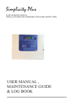
FIRE ALARM
CONTROL
PANEL
FVC01 - 08
USER MANUAL ,
MAINTENANCE GUIDE &
LOG BOOK
Radal Technology Limited
Unit 1, Webber Court
Billington Road, Burnley
Lancashire, BB11 5UB
Tel: +44 (0) 1282 463 770
Fax: +44 (0) 1282 463 771
.
USER MANUAL, MAINTENANCE GUIDE & LOG BOOK
CONTENTS
1. FIRE ALARM CONTROL PANEL SAFETY ISSUES………………………………………
How to use this Fire Alarm Panel safely
3
2. THE PURPOSE OF A FIRE ALARM SYSTEM………………………………………………
Introduction to fire alarms
3
3. USER RESPONSIBILITIES & MAINTAINENCE OF THE FIRE ALARM SYSTEM, INCLUDING THE
FACP & ITS INTEGRAL PSE ……………………………………………………………………
4
What the end users responsibility is,including daily, weekly,
quarterly & annual checks
4. PANEL INDICATIONS & CONTROLS …………………………..…………………………..
A list of indicator LEDs & Control Buttons on the Firevac Elite Fire Alarm Panel
4.1
GENERAL CONTROLS
4.2
ACCESSED CONTROLS
4.3
SUMMARY OF LED COMBINATIONS AND THEIR MEANING
4.4
CHECKING THE PANELS INDICATION LEDS
5
5. THE FIRE CONDITION …………………………………………………………………………
7
5.1
HOW THE FIREVAC ELITE INDICATES AN ALARM
5.2
TO TURN OFF THE ALARM SOUNDERS
5.3
A SECOND ALARM SIGNAL FROM A NEW DETECTION ZONE
5.4
TURNING ON THE ALARM SOUNDERS FROM THE FACP (I.E. EVACUATE ).
5.5
RESETTING THE PANEL
6. THE FAULT CONDITIONS ………………………………………………………………….
6.1
DIFFERENT TYPES OF FAULT
6.2
WHAT TO DO IF A FAULT CONDITION OCCURS
8
7. DISABLEMENTS …………………………………..………………………………………
7.1
REASONS FOR DISABLING CERTAIN PARTS OF A FIRE ALARM SYSTEM
7.2
TO DISABLE A ZONE AND/OR EXTERNAL SOUNDER
7.3
TO ENABLE A ZONE AND/OR EXTERNAL SOUNDER
10
8. USING SOUNDER DELAYS………………………………………………………………….
8.1
WHAT IS A SOUNDER DELAY
8.2
SOUNDER DELAY SETTING
8.3
HOW THE PANEL INDICATES SOUNDER DELAY
8.4
A FIRE ALARM CONDITION ON A DELAYED PANEL
8.5
OVERRIDING A DELAY IN THE EVENT OF A GENUINE FIRE ALARM
8.6
RESET THE SYSTEM IN THE EVENT OF A FALSE ALARM
8.7
TO TURN OFF THE SOUNDER DELAY
11
9. SYSTEM DESCRIPTION ………………………………………………………….………...
Lists system comments
12
10. FIRE ALARM LOG BOOK…………………………………………………………………..
A place for you to record details of events such as fires, false alarms, call
outs, etc.
13
11 COMMISSIONING THE SYSTEM, INCLUDING P.S.E.…………………………………
15
11.1 INSTALLATION & COMMISSIONING CERTIFICATE …………………………………
15
Approved Document No: RADAL.MAN-102
Issue: 3
Authorised: JMR
Date: 05/05/2003
PAGE 2
USER MANUAL, MAINTENANCE GUIDE & LOG BOOK
1. FIRE ALARM CONTROL PANEL SAFETY ISSUES
There is no need to open this fire alarm during normal operation. Any work carried out on this system must be
performed by a competent person who is familiar with this type of system.
This equipment will operate safely provided it has been installed correctly in compliance with the Installation
Manual.
It is recommended that the system is serviced frequently. It is customary to arrange a regular maintenance
contract with a competent organisation. (Ask the installation company for recommendations). The system
needs a thorough maintenance check annually at the very minimum.
If any part of this Fire Alarm Control Panel becomes damaged, contact the company responsible for system
maintenance to arrange repair / replacement.
European Union Directives Conformance Statement
This product has been manufactured in conformance with the requirements of all applicable
EU Council Directives. The Declaration of Conformance for this product is located at the
following Address: Radal Technology Limited, Unit 1 Webber Court, Billington Road, Burnley,
Lancashire BB11 5UB, United Kingdom
2. THE PURPOSE OF A FIRE ALARM SYSTEM
A Fire Alarm System is used to provide an early warning of a fire, so that the property can be evacuated and
the fire extinguished if it can be safely tackled, or the local fire brigade called, according to the company
evacuation procedure.
Alarms can come from Smoke or Heat Detectors, or manually be a person operating a Manual Call Point.
Split the system into Zones, each covering a different area of a building. This will indicate which area of the
system is giving the alarm (or fault).
During an alarm, the panel will start its sounders, and indicate which zone has the fire. It will also activate its
auxiliary relay.
Fault Monitoring
All circuits must be checked for line integrity. If a part of the system has a problem which may affect its
operation, a fault warning must be given by the fire alarm panel (LED & buzzer indication). The fault relay will
also activate.
Disablements
An engineer may be required to work on part of a system, while the system is still active (eg extending a
detection zone). During such circumstances, it would be advisable to disable that zone, so that it will not give
false alarms. Similarly you may wish to disable a zone that has a fault that has not been fixed, or a zone
covering an area with a temporary unusual environment, such as an area dusty because of construction work
etc.
Delays
In public places, it may be desirable to delay the activation of an alarm until the responsible person has verified
the cause of the alarm. (This would avoid a panic evacuation caused by a smoky room, or a maliciously
activated call point.) On verification of the alarm, the sounders can be started by pressing the override button,
or the panel can be reset in the case of a false alarm. If a delay has been set, it must be recorded on the
system configuration chart at the back of this manual.
Power Supply Equipment- General Description.
The Firevac Elite FACP has an integral linear power supply capable of supplying 1.2 amps in total. It contains a
current limited output for charging sealed lead acid batteries (7 Ah maximum). The PSE is monitored for main
supply failure, the battery not taking a charge and low battery voltage. If the battery voltage drops below
approximately 20VDC (a fault condition), the battery charging current will be turned off , thus stopping charging.
This PSE is only capable of supplying power to the CIE, and is not designed for any other use.
Approved Document No: RADAL.MAN-102
Issue: 3
Authorised: JMR
Date: 05/05/2003
PAGE 3
USER MANUAL, MAINTENANCE GUIDE & LOG BOOK
3. USER RESPONSIBILITIES & MAINTAINENCE OF THE FIRE ALARM
SYSTEM, INCLUDING THE FACP & ITS INTEGRAL PSE
According to the British Standard Code for the Design, Installation and Servicing of Fire Detection and Alarm
Systems for Commercial Buildings (BS5839: Pt 1: 1988), the owner or person having control of the premises
should appoint a responsible person to oversee the effective operation of the Fire Alarm System (Clause 28.1).
Below is a summary of the main functions the “Responsible Person” is expected to carry out. This summary is
not intended to replace Section Four of BS5839: Pt 1: 1988 (available from BSI, or your local library). It meant
to give a brief outline of user responsibilities for the safe upkeep of the Fire Alarm System. The number in
brackets shows the relevant BS5839: Pt 1: 1988 clauses.
The responsible person must:1.
Make sure that all maintenance work is carried out to keep the system working effectively, and keep
records of the maintenance and servicing of the system (28.1.1).
2. Prepare measures for dealing with fire alarms, faults, etc, which must be approved by the appropriate fire
authority before implementation (28.1.2).
3. Train all responsible people how to use the alarm system correctly, and show all building occupants what
to do if a fire starts (28.1.3).
4. Liase with maintenance personnel to ensure that cleaning, maintenance or building work does not interfere
with the functioning and reliability of the fire alarm system (28.1.4).
5. Check that no call point or detector is obstructed in any way (28.1.5).
6. Keep system records, drawings and instructions safe, and are kept up to date after any work on the
system. They should be readily available for reference purposes (28.2.1).
7. Record all relevant events in the Log Book (28.2.2).
8. Try to prevent false alarms by:
a)
Making staff and visitors to the building aware that a fire alarm system is in operation
(28.4.1.).
b)
Displaying notices in all areas where detectors are sited (28.4.2).
c)
Advising contractors to take suitable care in protected areas (28.4.3).
d)
Covering or disabling smoke detectors as precautions against dust and smoke during
building work. (28.4.4)
e)
Ensuring system checked for correct operation after work has been completed (28.4.5)
9. Ensure that the system is attended to regularly on a routine basis, i.e. testing procedure is carried out,
wiring check, etc (29.2).
10. Inspect the system daily and weekly as described below, and arrange quarterly maintenance visits. (29.2)
Also in special circumstances, i.e. following a fire, false alarm, etc, all out the maintenance engineer (29.3)
With the Firevac Elite Range of Fire Alarm Panels, we recommend the following tests are carried out: Daily Inspection
• Check that the green Power LED is lit.
• If there are any yellow fault LEDs lit, or the green Power LED is not lit, report the fault(s) to the designated
site maintenance engineer.
Weekly Test (you may wish to temporarily disconnect the Aux relay during the following Tests)
• Set off a manual call point or sensor to test the Fire Alarm panel responds and all the sounders activate.
• Do not test the same device each week. Test a different zone each week using a different call point or
detector so that eventually, all the devices will be tested.
• Reset the System by pressing 1,2,3 (Stop sounders, Silence fault tone, Reset).
• Turn key to controls enabled. Press the LED Test button. Check that all LEDs light, and the buzzer sounds
• Check that no call points or fire detectors are obstructed in any way. (eg New furniture or decorations)
Quarterly Test (to be carried out by authorised service personnel only)
• Check that any servicing or repairs required by all previous logbook entries has been undertaken.
• Visual inspection of the batteries and connections. Check the alarm sounders work on battery only.
• Activate a device from each zone to test the fire alarm. (As per weekly test).
Annual Test (to be carried out by authorised service personnel only)
•
Check every detector, call point, sounder and all auxiliary equipment for correct operation.
•
Check Transformer output Voltage (32 VAC), Charger Voltage (28.4V off load, adjusted with VR1) &
Battery Voltage (25-27V)
Every Five Years (to be carried out by authorised service personnel only)
• Carry out a complete wiring check in accordance with the testing and inspection requirements of the
relevant National wiring regulations (in the UK this is the IEE Wiring Regulations). The Batteries should be
replaced because SLA batteries have a working life of 5 years.
Approved Document No: RADAL.MAN-102
Issue: 3
Authorised: JMR
Date: 05/05/2003
PAGE 4
USER MANUAL, MAINTENANCE GUIDE & LOG BOOK
4. PANEL INDICATIONS & CONTROLS
FIRE / ZONES
1
POWER
SUPPLY FLT
GEN-FIRE
STOP-START
1
4
5
6
7
8
6
7
8
OFF
CONTROLS
ENABLED
ZONAL FAULT / DISABLEMENT / TEST
1
SYSTEM FLT
3
FLT
DEL
GEN-FAULT
2
2
3
4
5
GEN-S/C
SILENCE
RESET
2
3
FLT TONE
SCROLL /
4
ENGINEER
GEN-ZONE TEST
/ LED TEST
GEN-DISABLEMENT
DELAY
OVERRIDE
Two levels of control are available to the User(s) of this Fire Alarm Panel.
4.1 GENERAL CONTROLS
When the Panel is in its Normal state, the indicator lights on the front of the enclosure give a
comprehensive overview of the System’s current status. Any Fire and Fault conditions are clearly
displayed, disablements highlighted. For detailed descriptions of what each indicator means, please
refer to the table on the opposite page.
The only functions that can be performed by the User when the Panel is in its Normal state are:
•
Overriding any Delays, which may have been programmed into the Panel by pressing the
Sounder Override button.
•
Putting the Panel into the Accessed state – see below.
4.2 ACCESSED CONTROL (AVAILABLE TO AUTHORISED USERS ONLY)
To avoid unauthorised changes to critical parts of the Fire Alarm System, controls such as silencing
the Sounders, resetting an Alarm condition and implementing Disablements are only accessible via a
secure method of entry which puts the panel into the Accessed state.
To put the Panel into the Accessed State: Turn the key to the control enable position (please note
the key should not be removed when in this position). To leave the Accessed state, turn the key back
to the off position.
Information on how to used the accessed control can be found on Pages 8 to 11 of this User Manual.
Approved Document No: RADAL.MAN-102
Issue: 3
Authorised: JMR
Date: 05/05/2003
PAGE 5
USER MANUAL, MAINTENANCE GUIDE & LOG BOOK
4.3 SUMMARY OF LED COMBINATIONS AND THEIR MEANING
Use the table below to determine the condition of the panel.
LEDs LIT
POWER
LED CONDITION
CONSTANT GREEN
PANEL STATUS
The panel is supplied with power, and has no faults / fires (System Normal)
GEN FLT
ONLY
CONSTANT YELLOW
Problem with keyswitch connections
GEN FLT &
SUPPLY FLT
CONSTANT YELLOW
FLASHING YELLOW
There is a problem with either the mains supply or the battery backup
GEN FLT &
EARTH FLT
CONSTANT YELLOW
FLASHING YELLOW
There is a wiring problem. One of the cables is touching the earth screen.
GEN FLT &
ZONAL FLT
CONSTANT YELLOW
FLASHING YELLOW
There is an open circuit fault in the wiring of the zone indicated.
GEN FLT &
ZONAL FLT
GEN S/C
CONSTANT YELLOW
FLASHING YELLOW
FLASHING YELLOW
There is a short circuit fault in the wiring of the zone indicated.
GEN FLT &
SND FLT
CONSTANT YELLOW
FLASHING YELLOW
There is an open circuit fault in the wiring of one or both of the sounder
circuits
GEN FLT &
SND FLT
GEN S/C
CONSTANT YELLOW
FLASHING YELLOW
FLASHING YELLOW
There is a short circuit fault in the wiring of one or both of the sounder
circuits
GEN FLT &
SYSTEM FLT
CONSTANT YELLOW
CONSTANT YELLOW
A processor fault has occurred. To reset, turn keyswitch on then back off. If
problem persists, consult your dealer.
GEN FIRE
ONLY
CONSTANT RED
A manual evacuation has occurred.
The sounders will be active.
GEN FIRE &
ZONE FIRE
CONSTANT RED
CONSTANT RED
A fire has occurred in the zone indicated.
The sounders will be active.
GEN FIRE &
ZONE FIRE &
GEN DISABLE
& DEL
CONSTANT RED
CONSTANT RED
CONSTANT YELLOW
CONSTANT YELLOW
A fire has occurred in the zone indicated.
The sounders have a delay set, and will become active after the
programmed delay. To override the display, press delay override.
GEN DISABLE FLASHING YELLOW
(FAST – 4 HZ)
The panel is ready for selecting disable or test mode
GEN DISABLE FLASHING YELLOW
(SLOW–0.5HZ)
The panel is in SELECT DISABLEMENT MODE
GEN DISABLE FLASHING YELLOW
ZONEDISABLE
(SLOW–0.5HZ)
The user is scrolling through zones to select which one to disable/or user
has just enabled the zone.
GEN DISABLE CONSTANT YELLOW
ZONEDISABLE
CONSTANT YELLOW
The indicated zone is disabled.
GEN DISABLE CONSTANT YELLOW
DEL
CONSTANT YELLOW
The Sounders are delayed by the amount set on the rotary switch.
GEN TEST
ZONEDISABLE
FLASHING YELLOW
The indicated zone is in Test Mode.
FLASHING YELLOW
(VERY SLOW – 0.25 HZ)
4.4 CHECKING THE PANELS INDICATION LEDS
Turn the key switch to “Controls Enabled” position then press the LED test button (Button 4). All the LEDs on the
front panel will light, and the panel’s internal buzzer will also sound.
Approved Document No: RADAL.MAN-102
Issue: 3
Authorised: JMR
Date: 05/05/2003
PAGE 6
USER MANUAL, MAINTENANCE GUIDE & LOG BOOK
5. THE FIRE CONDITION
5.1 HOW THE FIREVAC ELITE INDICATES AN ALARM
FIRE / ZONES
1
POWER
SUPPLY FLT
GEN-FIRE
DEL
STOP-START
1
SILENCE
2
3
4
5
6
7
8
6
7
8
ZONAL FAULT / DISABLEMENT / TEST
1
GEN-FAULT SYSTEM FLT
2
FLT
2
3
4
5
GEN-S/C
RESET
3
FLT TONE
SCROLL /
4
ENGINEER
GEN-ZONE TEST
/ LED TEST
GEN-DISABLEMENT
DELAY
OVERRIDE
When the Firevac Elite Fire Alarm Panel is set into alarm by a Detector or Manual Call Point located in a zone
that is not already in alarm it will: -
•
•
•
Light the General Fire LED and appropriate Zone Fire LED(s) on the front of its enclosure
Sound Internal buzzer
Start the Alarm Sounder and Auxiliary output, (provided there is no Delay set on the sounders).
The building evacuation procedure should now be followed.
IMPORTANT NOTE: If a zone has been disabled, it can not be triggered into Alarm. This should be
remembered when disabling part of the system. (see Disabling zones or sounders later in this manual).
5.2 TO TURN OFF THE ALARM SOUNDERS
•
The Alarm Sounders may be silenced by turning the control key to “Control Enable” position and momentarily
pressing the Start/Stop button.
The Alarm Sounders will cease to sound but the light(s) for the Zone(s) in Alarm and the red General Fire light will
stay lit. The Auxiliary Fire relay will remain active. (The Panels internal buzzer can also be silenced by pressing
the Silence int flt button (button 2)).
5.3 A SECOND ALARM SIGNAL FROM A NEW DETECTION ZONE
If another detection Zone is activated after the Alarm Sounders have been silenced, the panel will: -
•
•
•
Restart the sounders
Light the Zone Fire LED(s) for any new Zone(s) in alarm
Keep the light(s) for the previous Zone(s) in fire, and General Fire lit.
5.4 TURNING ON THE ALARM SOUNDERS FROM THE FACP (I.E. TO EVACUATE THE BUILDING).
•
With the control key in “Controls Enabled” position, momentarily pressing the Start/Stop will cause the Alarm
sounders to sound.
Pressing the Start/Stop button again will Silence the Alarm Sounders.
Note: If the Alarm Sounders have been disabled, pressing the Stop/Start button will have no effect.
5.5 RESETTING THE PANEL
•
•
Check the cause of the alarm activation. If the cause of the alarm was an activated call point, reset it (if
resettable type), or fit a new glass element (if glass type). If the cause of the alarm was by detector activation
(eg cooking smoke), the smoke will have to be cleared from the room before the panel can be reset. Reset
the panel by pressing the reset button (3) after the sounders and panel buzzer have been silenced.
If the call point is still active, or the detector is still smoky, this will cause another alarm straight after the
panel is reset, so will set off alarm bells again.
Approved Document No: RADAL.MAN-102
Issue: 3
Authorised: JMR
Date: 05/05/2003
PAGE 7
USER MANUAL, MAINTENANCE GUIDE & LOG BOOK
6. THE FAULT CONDITION
6.1 DIFFERENT TYPES OF FAULT
The fire alarm monitors itself, and any equipment connected to it, for any faults that can occur. If a fault occurs, the Panel
responds by activating its Internal buzzer and lighting the General Fault light and any other Fault light(s) relevant to the
Fault. The Panel’s Fault relay will also activate. Typical faults are described below: -
General Fault
FIRE / ZONES
POWER
1
SUPPLY FLT
GEN-FIRE
2
3
4
5
6
7
8
6
7
8
FLT
ZONAL FAULT / DISABLEMENT / TEST
1
2
3
4
5
DEL
GEN-FAULT SYSTEM FLT GEN-S/C
STOP-START
1
SILENCE
RESET
2
SCROLL /
3
4
FLT TONE
GEN-ZONE TEST
ENGINEER
/ LED TEST
GEN-DISABLEMENT
DELAY
OVERRIDE
Zone Fault
FIRE / ZONES
POWER
1
SUPPLY FLT
GEN-FIRE
GEN-FAULT
STOP-START
1
2
3
4
5
6
7
8
6
7
8
FLT
ZONAL FAULT / DISABLEMENT / TEST
1
2
3
4
5
DEL
SYSTEM FLT GEN-S/C
SILENCE
RESET
2
SCROLL /
3
4
FLT TONE
GEN-ZONE TEST
ENGINEER
/ LED TEST
GEN-DISABLEMENT
1
SUPPLY FLT
GEN-FIRE
GEN-FAULT
STOP-START
1
2
Short Circuit Fault
3
4
5
6
7
8
6
7
8
FLT
ZONAL FAULT / DISABLEMENT / TEST
1
2
3
4
5
DEL
SYSTEM FLT GEN-S/C
SILENCE
RESET
2
SCROLL /
3
4
FLT TONE
GEN-ZONE TEST
ENGINEER
DELAY
OVERRIDE
Power Supply Fault
FIRE / ZONES
1
SUPPLY FLT
GEN-FIRE
GEN-FAULT
STOP-START
1
2
3
4
5
6
7
8
6
7
8
FLT
ZONAL FAULT / DISABLEMENT / TEST
1
2
3
4
5
DEL
SYSTEM FLT GEN-S/C
SILENCE
RESET
2
SCROLL /
3
4
FLT TONE
GEN-ZONE TEST
ENGINEER
/ LED TEST
GEN-DISABLEMENT
DELAY
OVERRIDE
1
SUPPLY FLT
GEN-FIRE
GEN-FAULT
STOP-START
1
2
3
4
5
6
7
8
6
7
8
FLT
ZONAL FAULT / DISABLEMENT / TEST
1
2
3
4
5
DEL
SYSTEM FLT GEN-S/C
SILENCE
2
FLT TONE
RESET
3
SCROLL /
4
The Power supply Fault light flashes when the Mains supply
has failed or the standby batteries or its charger is faulty. If
the mains supply fails, the panel will only operate for the
standby period dictated by the size of the batteries fitted. If
the batteries or charger fails at the same time as the Mains,
the Panel will be inoperative.
System Fault
FIRE / ZONES
POWER
If the Fault is a short circuit fault, then the S/C LED will be lit.
This GEN S/C LED will be lit for S/C faults on the zone
and sounder circuits. It can take up to 60 seconds from repairing
a fault for the display to clear.
/ LED TEST
GEN-DISABLEMENT
POWER
The relevant Zone Fault light flashes when there is a
wiring problem on a Zone or detector has been removed from
its base. It should be noted that any alarms raised on the
fault zone(s) may not be recognised by the Fire Alarm Panel
until the Fault Conditions have been cleared. It can take up to
60 seconds from repairing a fault for the display to clear.
DELAY
OVERRIDE
FIRE / ZONES
POWER
The General Fault LED is a common indicator that lights
when there is a Fault on any part of the Fire Alarm Systems.
It is usually lit in tandem with at least one other fault light
which conveys more precise information on the type of
Fault detected.
If this light is lit by itself, it indicates a keyswitch fault.
ENGINEER
GEN-ZONE TEST
/ LED TEST
GEN-DISABLEMENT
DELAY
OVERRIDE
Approved Document No: RADAL.MAN-102
Issue: 3
Authorised: JMR
Date: 05/05/2003
The System Fault LED lights when the Panel’s micro-processor
has Reset, typically after excessive electrical interference, or if
the contents of its memory have been corrupted. This fault can
only be cleared by turning the key switch from off position to
control enable position and then turn key to off position again. If
the fault re-occurs within two minutes, this is indicative of a
corrupt memory and expert advice should be sought.
PAGE 8
USER MANUAL, MAINTENANCE GUIDE & LOG BOOK
Earth Fault
FIRE / ZONES
POWER
1
SUPPLY FLT
GEN-FIRE
GEN-FAULT
STOP-START
1
2
3
4
5
6
7
8
6
7
8
FLT
ZONAL FAULT / DISABLEMENT / TEST
1
2
3
4
5
DEL
SYSTEM FLT GEN-S/C
SILENCE
RESET
2
SCROLL /
3
4
FLT TONE
GEN-ZONE TEST
ENGINEER
/ LED TEST
GEN-DISABLEMENT
DELAY
OVERRIDE
Sounder Fault
FIRE / ZONES
POWER
1
SUPPLY FLT
GEN-FIRE
GEN-FAULT
STOP-START
1
2
3
4
5
6
7
8
6
7
8
FLT
ZONAL FAULT / DISABLEMENT / TEST
1
2
3
4
5
DEL
SYSTEM FLT GEN-S/C
SILENCE
2
FLT TONE
The Earth Fault light flashes when the panel detects an earth
fault (short circuit to earth) on the wiring to any part of the
control panel.
RESET
3
SCROLL /
4
ENGINEER
GEN-ZONE TEST
/ LED TEST
GEN-DISABLEMENT
DELAY
OVERRIDE
The Sounder status light flashes when there is a wiring fault
on the Sounder Circuits. Depending on where the fault
has occurred, one or all of the Alarm Sounders may no longer
be operative.
If the fault is a short circuit fault, then the S/C LED will also
be lit.
6.2 WHAT TO DO IF A FAULT CONDITION OCCURS
If a fault occurs, the responsible person should:
•
•
Turn keyswitch to Controls enabled and press silence flt tone button (button 2) to silence the fault buzzer.
Write down the fault (s) in the Log Book at the back of this Manual. Take appropriate action to correct the fault
(Usually by contacting the service engineer)
On the Firevac Elite panel, the fault indications (except system fault) are non latching. That is, when the fault has been
cleared, the fault indication will turn off. When all faults have been cleared, the panel will return to its quiescent (normal)
condition.
When a fault has been rectified the indicator light for that Fault is automatically turned off. If all Faults are cleared, the
General Fault light will go out and the Panel’s Internal Sounder will be silent (if not already muted).
Approved Document No: RADAL.MAN-102
Issue: 3
Authorised: JMR
Date: 05/05/2003
PAGE 9
USER MANUAL, MAINTENANCE GUIDE & LOG BOOK
7. DISABLEMENTS
7.1 REASONS FOR DISABLING CERTAIN PARTS OF A FIRE ALARM SYSTEM.
Certain Fire Alarm Panels can be temporarily disabled (i.e. switch off) to suit prevailing conditions. For example, if there is
a risk of a False Alarm in a zone, say from vehicle exhaust smoke in a loading bay, it is possible for the user to disable
that zone during the risk period and then enable it again afterwards. During a disablement of a zone(s), no fire or fault
signal will be processed for that zone(s). A zone(s) in a non-alarm state can only be disabled, that is zones already in fire
cannot be disabled.
External sounders can also be disabled as could be required in certain conditions.
7.2 TO DISABLE A ZONE AND/OR EXTERNAL SOUNDERS.
1.
Turn control key to “Controls Enable” position;
2.
Press “Engineer” switch momentarily, this will cause General Disablement LED to flash (fast). This means the
panel is in disable/enable mode;
3.
Press scroll (No. 4) switch once and this will cause the General Disablement LED to flash (slow);
4.
Press scroll (No. 4) switch once again and this will cause Zone 1 Disablement LED to light steady;
5.
Pressing scroll (No. 4) switch will cause the zone disablement LED to toggle to zone 2 and so on;
FIRE / ZONES
1
2
POWER
SUPPLY FLT
GEN-FIRE
3
4
5
6
7
8
6
7
8
FLT
ZONAL FAULT / DISABLEMENT / TEST
1
2
3
4
5
DEL
GEN-FAULT SYSTEM FLT GEN-S/C
STOP-START
1
SILENCE
2
FLT TONE
RESET
3
SCROLL /
4
ENGINEER
GEN-ZONE TEST
/ LED TEST
GEN-DISABLEMENT
DELAY
OVERRIDE
6.
Select zone to be disabled. For example, if Zone 3 is selected and with Zone 3 disablement LED lit (steady) and
General Disablement LED flashing slow, pressing “Engineer” will cause General Disablement LED light to change
to steady. This means that zone 3 is now disabled;
7.
Switch controls key to off position, then both the disabled Zone Disablement LED and the General Disablement
LED will remain lit (steady.
7.3 TO ENABLE A ZONE AND/OR EXTERNAL SOUNDERS.
1.
Turn key to “Controls enable” position (since a zone is already disabled at this time, the General Disablement LED
with stay lit (steady);
2.
Press “Engineer” switch once and this will cause the General Disablement LED to flash (fast);
3.
Press scroll (No. 4) switch until the light is steady at the disabled zone;
4.
Press “Engineer” and this will cause the General Disablement LED to flash (slow);
5.
Turn control Key to “Off” position and this will turn off the General Disablement and Zone Disablement LEDs.
NOTES:
The option of disabling or enabling zones 2, 3, 4, 5, 6, 7 and 8 is only available if these zones are present on the
panel
Approved Document No: RADAL.MAN-102
Issue: 3
Authorised: JMR
Date: 05/05/2003
PAGE 10
USER MANUAL, MAINTENANCE GUIDE & LOG BOOK
8. USING SOUNDER DELAYS
8.1 WHAT IS A SOUNDER DELAY
In certain circumstances it may be desirable to have a delay between the panel detecting a fire, and starting its external
sounders, to allow the responsible person to check the cause of the alarm, to stop building evacuation by an obvious false
alarm. If the cause of the Alarm is found to be a true fire hazard, the Delay can be overridden and the Alarm Sounders
activated immediately. Alternatively, in the case of a false alarm, the Panel can be reset.
8.2 SOUNDER DELAY SETTING
On the Firevac Elite panel, the sounder delay is global. That is all zones will be delayed by the same amount. The delay
can be set between 1 minute and 9 minutes, by turning the rotary dial to the relevant position, or the delay can be left off
(sounders activate immediately), by leaving the dial at the 0 position.
8.3 HOW THE PANEL INDICATES SOUNDER DELAY
If a Delay has been programmed into the Panel, the General Disablement & DEL(AY) LEDs will be lit. When a zone
processes an alarm signal, the panel will indicate fire in the usual way, but the sounders will not be active until the delay
period has expired. To override this delay, press Delay Override Switch, which will cause the external sounders to
energise. If Delay is not programmed, the Delay Override Switch has no function.
8.4 A FIRE ALARM CONDITION ON A DELAYED PANEL
When an alarm occurs on a Delayed Panel, the panel will: -
•
Light its General Fire and appropriate Fire Zone light(s)
•
Sound its Internal buzzer
•
Start the Delay countdown sequence
•
Wait until the end of the delay, then start the sounders.
8.5 OVERRIDING A DELAY IN THE EVENT OF A GENUINE FIRE ALARM
If on investigation the cause of the Alarm is found to be a true fire hazard, pressing the Delay Override, will active the
Alarm Sounders and Outputs with immediate effect.
8.6 RESET THE SYSTEM IN THE EVENT OF A FALSE ALARM
If, on investigation, the cause of the Alarm is found to be false, turn the Key switch to the “Controls Enabled” position and
press reset button.
8.7 TO TURN OFF THE SOUNDER DELAY
There are two ways of turning off the sounder delay:1
Return the rotary switch to the 0 position.
2
Turn key to controls enabled pos ition. Press engineer button (to select disablement mode). Press delay override
(the DEL LED will now go off to show that the delay is no longer active). Pressing Delay Override again will
toggle the delay back on.
Approved Document No: RADAL.MAN-102
Issue: 3
Authorised: JMR
Date: 05/05/2003
PAGE 11
USER MANUAL, MAINTENANCE GUIDE & LOG BOOK
9. SYSTEM DESCRIPTION
This must be fully recorded by an authorised Engineer before system handover.
FIRE ZONE INFORMATION
ZONE
ZONE DESCRIPTION
NUMBER
A brief description of all the rooms and areas contained in each zone
Sounder
Circuit
Circuit 1
SOUNDER CIRCUIT DESCRIPTION
A brief description of all the rooms and areas contained in each circuit
QTY
MCP
QTY
HEADS
QTY
SNDR
QTY
BELLS
Circuit 2
Any Other Information about The Sounder Circuits
SOUNDER DELAY TIME (ENTER 0 IF NOT USED)
OUTPUT ROUTING INFORMATION
TYPE OF OUTPUT
CONNECTED
Auxiliary Output
Yes/No
Fault Output
WHAT HAPPENS WHEN ACTIVATED
Yes/No
ADDITIONAL INFORMATION
Any additional information the User needs to know about should be inserted into this box including details of the routing of
any additional outputs, details of inputs utilised, etc.
THE INFORMATION ABOVE WAS COMPLETED BY
NAME:
_________________________________________________________
COMPANY:
_________________________________________________________
POSITION:
_________________________________________________________
DATE:
_________________________________________________________
Approved Document No: RADAL.MAN-102
Issue: 3
Authorised: JMR
Date: 05/05/2003
PAGE 12
USER MANUAL, MAINTENANCE GUIDE & LOG BOOK
10. FIRE ALARM LOG BOOK
It is recommended that this LOG BOOK section of the Manual be maintained by the responsible person(s) on site, who
should ensure every event is properly recorded (including fire alarm conditions, failures, tests, temporary disconnections,
disablements, enablements, dates of installing engineers’ visits together with a note of any outstanding work or conditions.
). This LOG BOOK must be available for inspection at all times.
You can Photocopy this log book to provide extra pages for when this book is full.
Company:
Site Address:
Contract No:
Responsible Person(s) on Site:
For Service (Normal hours Mon-Fri) Tel:
For Service (Other times) Tel:
ZONE
DATE
TIME
DETAILS OF EVENT
(INCLUDING CAUSE IF KNOWN)
Approved Document No: RADAL.MAN-102
Issue: 3
Authorised: JMR
Date: 05/05/2003
ACTION
REQUIRED
DATE
INITIALS
COMPLETED
PAGE 13
USER MANUAL, MAINTENANCE GUIDE & LOG BOOK
ZONE
DATE
TIME
DETAILS OF EVENT
(INCLUDING CAUSE IF KNOWN)
Approved Document No: RADAL.MAN-102
Issue: 3
Authorised: JMR
Date: 05/05/2003
ACTION REQUIRED
DATE
SIGNED
COMPLETED
PAGE 14
USER MANUAL, MAINTENANCE GUIDE & LOG BOOK
11 COMMISSIONING THE SYSTEM, INCLUDING P.S.E.
•
The commissioning of this fire alarm system should be performed by a qualified commissioning engineer.
•
The system layout drawing should be checked for accuracy & stored in a safe place, accessible to any fire officer.
•
The system set-up data chart (RADAL.MAN-102, section 9) should be checked for accuracy.
•
The fire alarm log book contact details should be checked for completeness.
•
The system should be checked in accordance with BS5839 Pt1 26.2 for compliance with the recommendations.
•
The insulation of cables should be checked in accordance with BS5839 Pt1 26.3 for compliance.
•
The Earthing should be checked in accordance with BS5839 Pt1 26.4 for compliance.
•
The PSE mains feed from a 3A spur should be checked.
•
The PSE Charger voltage should be checked & adjusted if necessary (27.8V with batteries disconnected).
•
The battery voltage should be checked (should be between 24 & 27V)
•
The entire system should be checked in accordance with BS5839 Pt1 26.5 for satisfactory operation.
•
Any deviations from BS5839 Pt1 26.6 should be listed in the Certificate of Installation & Commissioning.
•
The Certificate of Installation & Commissioning should be completed, and the whole user manual passed to the
relevant person on site. (They should be given a brief training on the basic operation of the FACP)
11.1 INSTALLATION & COMMISSIONING CERTIFICATE
Before this User Manual is handed over to the relevant person(s) on site, the following certificate must be completed by
the installation/commissioning engineer. The System Description sheet should also be completed on Page 13 as should
the relevant parts of the Log Book section on Page 14.
Approved Document No: RADAL.MAN-102
Issue: 3
Authorised: JMR
Date: 05/05/2003
PAGE 15
USER MANUAL, MAINTENANCE GUIDE & LOG BOOK
CERTIFICATE OF
OF
CERTIFICATE
INSTALLATION
AND COMMISSIONING
This is to certify the correct installation and commissioning of a Firevac Elite Fire Alarm system at:
Company:
_________________________________________________________________________________
Address:
_________________________________________________________________________________
_________________________________________________________________________________
_________________________________________________________________________________
* System complies with BS5839 Pt1: 1988, sub clause 26.2. The installation has been inspected for compliance with the
recommendations of the code.
* System complies with BS5839 Pt1: 1988, sub clause 26.3. The insulation of cables and wires has been tested.
* System complies with BS5839 Pt1: 1988, sub clause 26.4. The earthing has been tested.
* System complies with BS5839 Pt1: 1988, sub clause 26.5. Whole system has been tested for satisfactory operation.
* System complies with BS5839 Pt1: 1988, sub clause 26.6. It is certified that the installation complies with the
recommendations of the code, other than the following deviations.
_______________________________________________________________________________________________
_______________________________________________________________________________________________
_______________________________________________________________________________________________
_______________________________________________________________________________________________
_______________________________________________________________________________________________
_______________________________________________________________________________________________
_______________________________________________________________________________________________
_______________________________________________________________________________________________
_______________________________________________________________________________________________
_______________________________________________________________________________________________
_______________________________________________________________________________________________
_______________________________________________________________________________________________
_______________________________________________________________________________________________
I have been advised about the recommendations of BS5839 Pt1: 1988 clause 29 relating to servicing the system. In
accordance with BS5839 Pt1: 1988, sub clause 26.1, system drawings and the user manual/log book have been supplied
and received by the following person (the recipient/user must complete their details here):
User’s name: _____________________ User’s Job Title: _____________________ Date: ____________________
For and on behalf of: ______________________________ User’s Signature:* _______________________________
*Check The System Details (Page 12) and Log book call out information (Page 13) are completed before signing this Certificate
Signed (Commissioning Engineer: ________________________________________ Date: ____________________
For and on behalf of: _____________________________________________________________________________
The Installation Manual is located: __________________________________________________________________
Approved Document No: RADAL.MAN-102
Issue: 3
Authorised: JMR
Date: 05/05/2003
PAGE 16