1
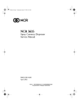
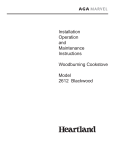
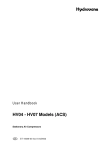
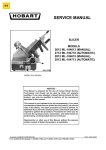
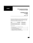
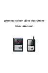
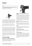
Video Intercom and Doorphone
System
VDP311
User manual
V3.2
1. Monitor Unit Description
The VDP311 system is a flexible and user-friendly system that allows a number
of monitors to be used with a number of door units with cameras. The monitors
allow visibility of the callers via the camera in the door units and, when used with
the optional electronic lock, enable the resident to electronically open the door
for the caller.
9
10
1
6
8
2
7
3
9
4
5
11
VDP311 Monitor Unit
1.
2.
3.
4.
5.
6.
7.
8.
9.
10.
11.
Talk button
Select button
Monitor / Settings button
Door unlock button
Microphone
Activity indicator
Power indicator
Display Screen
Speaker
DC power socket
Terminal Blocks
Page 2
2. Wall Mounting
Fix the mounting bracket to the wall first using the fixing holes (2), then connect
wiring and finally hook the monitor unit over the hooks (1) on the bracket
3. Electrical Connections
The connections between the Door Unit (left) and the Monitor (right) are made
using 4-wire cable as shown below. If you add an additional monitor you can use
this as an intercom if all 5 wires are connected as shown
Page 3
You can use any 4-core cable to make these connections, but screened and/or
armoured cables are most secure. To connect additional monitors you will need
to use 5-core cables to prevent interference between the monitors – only the
monitor that accepts the call will be in communication with the caller. It is
possible to use 4-cores for the signal and the screen for the ground connection.
The monitors and door cameras are each provided with terminals and a short
cable with appropriate terminal connectors already attached. Use screw-type
terminal blocks to connect to these, or use a soldered joint if you are suitably
experienced. You can also purchase lengths of cable with terminal connectors
already attached.
Connect similar colours together. That is, connect red to red, blue to blue, yellow
to yellow and white to white. The green wire does not need to be connected
(unless you have additional monitors or additional doors) and should be on the
left of the terminal block when looking at the rear of the unit as in the image in
section 1.
A power adaptor must be plugged into the monitor. This will also supply power
to the door camera unit.
The (optional) electronic lock is connected to the door camera unit, using a twin
cable.
Interface Cable Description:
1.
2.
3.
4.
Yellow (Video)
Black (Ground)
Blue (Audio)
Red (+12V DC)
Page 4
4. Operation
Caller at Door
1. Caller presses the Call button on the Door Camera
2. Both the monitor and the Door Camera will play the selected ring tone
and the Activity LED will light on the monitor
3. The camera will turn on and the image of the caller will be displayed on
the Monitor screen
4. Press the Call button on the monitor to accept the call
5. You can then talk hands-free with your caller
6. Press the Unlock button to release the door lock (optional)
7. Press the Call button again to finish the call
Monitoring External View
1. Press the Monitor / Settings button on the monitor at any time
2. The Monitor will show the outside view and you can talk hands-free with
anyone near the door
3. While monitoring the outside, you can unlock the door by pressing the
Unlock
Selecting Ring Tones
1. Press the Monitor / Settings button and hold for 5 seconds
2. The currently selected ring-tone will play
3. Use the Select button to cycle through the different ring tones
4. Press the Monitor / Settings button again to confirm your selection
5. The monitor will beep twice to accept the new selection
Selecting Ring Volume
1. Press the Select button and hold for 5 seconds
2. Use the Monitor / Settings button to select volume required
3. Press the Select button again to confirm volume
4. The monitor will beep twice to accept the new volume
Page 5
5. Door Camera
FRONT VIEW
1. Fixing hole (connects to
mounting bracket)
2. Microphone
3. Camera
4. Light sensor (controls
infra-red)
5. Call button
6. Speaker
7. Fixing hole
1
2
3
4
5
6
7
2
2
1
3
4
5
REAR VIEW
1. Fixing holes on bracket
2. Connection to main unit
3. Space in bracket for wires etc.
4. Electronic lock connection
terminals (+ve and –ve)
5. Video monitor connection
terminal
6
Interface Cable Description:
1.
2.
3.
4.
the
Yellow (Video)
Black (Ground)
Blue (Audio)
Red (+12V DC)
Page 6
6. Technical Specification
•
Monitor dimensions: 230mm x 165mm x 35mm
•
Camera dimensions: 150mm x 120mm x 30mm
•
LCD on monitor: 7inch diagonal, TFT technology
•
Image sensor on camera: 1/3” CMOS, 1440 x 234 effective pixels
•
Audio and video communication between monitor and camera (video from
camera to monitor only)
•
Infra-red night vision using automatic sensor
•
Selectable ring tones
•
Electronic lock controlled from monitor (optional)
•
Brightness, volume and contrast adjustments
•
Hands-free design
•
Standard 4-wire connections
•
Power supply: 12V DC (country specific mains adaptor included)
•
System supports up to 5 monitors and 3 cameras
7. Installing the Electric Rim Lock
•
This lock fits onto the inside of the door, with the additional keyplate (if required) mounted on
the outside with the barrel of the lock passing through the door and into the slot on the rear of
the lock assembly
Page 7
•
The strike plate should be mounted on the door frame with the bolt passing centrally. The
roller, which helps release the bolt, passes directly over the bump at the top (or bottom if
mounted on left) on the striker plate
•
A 2-core wire is required to be fitted from the Door camera unit to the lock.
•
The button on the inside of the door assembly allows the door to be unlocked from inside –
even when electricity is not available
•
Three keys are provided, which enable the lock to be opened from the outside at all times
Page 8