1
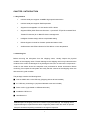
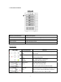
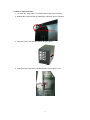
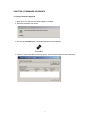
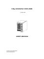
5 Bay SAS/SATA II HDD JBOD XJ-SA12-005 USER’S MANUAL Document number: MAN-00079-C P/N: H88TJ53660-AP010-0 Important Information Warranty Our product is warranted against defects in materials and workmanship for a period of one year from the date of shipment, as evidenced by receipts or other documentation. The manufacture at its option, repair or replace equipment that proves to be defective during the warranty period. This warranty includes parts and labor. The media on which you receive software are warranted not to fail to execute programming instructions, due to defects in materials and workmanship, for a period of 90 days from date of shipment, as evidenced by receipts or other documentation. The manufacture will, at its option, repair or replace software media that do not execute programming instructions if the manufacture receives notice of such defects during the warranty period. The manufacture does not warrant that the operation of the software shall be uninterrupted or error free. National Instruments believes that the information in this document is accurate. The document has been carefully reviewed for technical accuracy. In the event that technical or typographical errors exist, the manufacture reserves the right to make changes to subsequent editions of this document without prior notice to holders of this edition. The reader should consult National Instruments if errors are suspected. In no event shall the manufacture be liable for any damages arising out of or related to this document or the information contained in it. EXCEPT AS SPECIFIED HEREIN, THE MANUFACTURER MAKES NO WARRANTIES, EXPRESS, IMPLIED, OR STATUTORY AND DISCLAIMS ANY IMPLIED WARRANTY OR CONDITION OF MERCHANTABILITY, FITNESS FOR A PARTICULAR PURPOSE, OR NON-INFRINGEMENT, OR A WARRANTY THAT THE PRODUCT WILL OPERATE ERROR FREE. IN NO EVENT SHALL THE MANUFACTURER BE LIABLE FOR THE COST OF PROCUREMENT OF SUBSTITUTE HARDWARE, SOFTWARE, OR SERVICES, LOST PROFITS, LOST DATA, OR ANY SPECIAL, INDIRECT, CONSEQUENTIAL, OR INCIDENTAL DAMAGES, HOWEVER CAUSED AND ON ANY THEORY OF LIABILITY ARISING IN ANY WAY OUT OF THIS AGREEMENT OR THE SERVER. THIS LIMITATION SHALL APPLY EVEN IF THE MANUFACTURER HAS BEEN ADVISED OF THE POSSIBILITY OF SUCH DAMAGES, AND NOTWITHSTANDING ANY FAILURE OF ESSENTIAL PURPOSE OF ANY LIMITED REMEDY PROVIDED HEREIN. This limitation of the liability of the manufacturer will apply regardless of the form of action, whether in contract or tort, including negligence. Any action against the manufacturer must be brought within one year after the cause of action accrues. The manufacture shall not be liable ii for any delay in performance due to causes beyond its reasonable control. The warranty provided herein does not cover damages, defects, malfunctions, or service failures caused by owner’s failure to follow the manufacture installation, operation, or maintenance instructions; owner’s modification of the product; owner’s abuse, misuse, or negligent acts; and power failure or surges, fire, flood, accident, actions of third parties, or other events outside reasonable control. Copyright Under the copyright laws, this publication may not be reproduced or transmitted in any form, electronic or mechanical, including photocopying, recording, storing in an information retrieval system, or translating, in whole or in part, without the prior written consent of the manufacture. Trademarks Product and company names mentioned herein are trademarks or trade names of their respective companies. Changes The Manufacturer reserves the right to revise this publication and to make changes in the content hereof without the obligation of the manufacturer to notify any person of such revision or changes. iii SAFETY PRECAUTIONS Before getting started, please read the following important cautions: All cautions and warnings on the equipment or in the manuals should be noted. Most electronic components are sensitive to electrical static discharge. Therefore, be sure to ground yourself at all times when installing the internal components. Use a grounding wrist strap and place all electronic components in static-shielded devices. Grounding wrist straps can be purchased in many electronic supply stores. Do not open the top cover of the system. If opening the cover for maintenance is a must, only a trained technician should do so. Integrated circuits on computer boards are sensitive to static electricity. Before handling a board or integrated circuit, touch an unpainted portion of the system unit chassis for a few seconds. This will help to discharge any static electricity on your body. Place this equipment on a reliable surface when install. A drop or fall could cause injury. Please keep this equipment away from humidity. Do not leave this equipment in an environment unconditioned, out of operation or storage temperature range may damage the equipment. Never pour any liquid into ventilation openings, this could cause fire or electrical shock. Make sure the voltage of the power source is within the specification on the label when connecting the equipment to the power outlet. The current load and output power of loads shall be within the specification. This equipment must be connected to reliable grounding before using. Place the power cord out of the way of foot traffic. Do not place anything over the power cord. The power cord must be rated for the product, voltage and current marked on the product’s electrical rating label. The voltage and current rating of power cord should be greater than the voltage and current rating marked on the product. If the equipment is not used for a long time, disconnect the equipment from mains to avoid being damaged by transient over-voltage. Never open the equipment. For safety concerns, only qualified service personnel should open the equipment for maintenance. If one of the following situations arise, the equipment should be checked by service personnel: 9 The power cord or plug is damaged. 9 Liquid has penetrated the equipment. 9 The equipment has been exposed to moisture. 9 The equipment does not work well or will not work according to its user manual. iv 9 The equipment has been dropped and/or damaged. 9 The equipment has obvious signs of breakage. 9 Please disconnect this equipment from the AC outlet before cleaning. Do not use liquid or detergent for cleaning. The use of a moisture sheet or cloth is recommended for cleaning. Note: Product features and specifications are subject to change without notice. v Table of Contents CHAPTER 1 INTRODUCTION ........................................................................1 1.1 Key features........................................................................................1 1.2 Checking list .......................................................................................1 1.3 Front Panel Features ..........................................................................2 1.4 Rear Panel Features...........................................................................3 CHAPTER 2 INSTALLATION OVERVIEW.......................................................4 2.1 How to install and remove HDD Trays? ..............................................4 2.2 How to replace the fan? ......................................................................5 2.3 Powering on the device ......................................................................6 CHAPTER 3 FIRMWARE UPGRADES ...........................................................7 3.1 In-band Firmware Upgrade .................................................................7 3.2 Out-of-band Firmware Upgrade ..........................................................8 vi CHAPTER 1 INTRODUCTION 1.1 Key features 9 miniSAS wide port supports 1200MB/s high speed transmission 9 miniSAS wide port supports JBOD expansion 9 Supports hot-swappable 3.5” SAS and/or SATA II drives 9 Supports SES2 (SCSI Enclosure Services – 2) and SAF-TE (SCSI Accessed Fault Tolerant Enclosures) for In-Band Enclosure management. 9 Intelligent firmware design without complicated setting 9 RS232 Support Console for firmware update and status check 9 Audible alarm and LEDs indicators for FAN failure or Over temperature 1.2 Checking list Before removing the subsystem from the shipping carton, visually inspect the physical condition of the shipping carton. Exterior damage to the shipping carton may indicate that the contents of the carton are damaged. If any damage is found, do not remove the components; contact to the dealer where the subsystem was purchased for further instructions. Before continuing, first unpack the subsystem and verify that the contents of the shipping carton are all there and in good condition. The package contains the following items: ■ One set JBOD with 5 units HDD tray (Shipping without drives installed) ■ 3.5” HDD tray screw bag x1 (20 pieces flathead screw are included) ■ Power cord x1 (type based on different territories.) ■ Installation CD-Rom x1 ■ User Manual x1 Note:Inspect the shipping cartons for evidence of physical damage. If a shipping carton appears damaged, request that the carrier’s agent be present when the carton is opened. Keep all contents and packing materials for the agent’s inspection. 1 1.3 Front Panel Features nPower on/off LED button Power on/off system oMute Button When Buzzer is enabled and triggered, push Mute button to turn off pOver Temperature LED LED indicate the system exceeds the threshold temperature qFan Fail LED LED indicate the fan fail rHDD tray Screw the HDD into drive tray LED indicators LED NAME Color definition Behavior Fan fail LED: On, when system detects fan abnormality Red Off, normal Over Temp: On, when system temperature exceeds the RED threshold temperature Power: On:When system is powered on GREEN (Combine with power button) HDD Activity: On, when HDD is connected. BLUE Flash, when accessing HDD Off, when system does not detect the HDD. HDD Fail: Normally this LED is controlled by Host RAID card or RED HBA. It is ON to indicate HDD failure, Rebuild or Locating, but varies from different HBAs 2 1.4 Rear Panel Features X Y Z [ \ ] nHost miniSAS 4x connector for HBA or RAID adapter oExpansion miniSAS 4x connector for JBOD expansion Connect to host COM port. pRS-232 Phone Jack Console can be used for firmware upgrade, and detail status monitor if necessary qFactory reserved switch 1︰Reserve 2︰Buzzer Enable — OFF/Disable;ON/Enable (default) rHeart Beat LED Heart Beat indicator ]Power AC inlet Connect a power cord to the AC inlet for power supply 3 CHAPTER 2 INSTALLATION OVERVIEW Warning:Before removing or install the unit, be sure that the unit is not turned on or connected to the AC power. 2.1 How to install and remove HDD Trays? 1. Press the latch to the right side by the thumb. 2. Push the tray door outward by the forefinger at the same time. 3. Pull the HDD tray from the bay gently. 4. Secure the HDD to the tray by using four mounting screws shown as below. Rear view of HDD tray 5. Slide the HDD tray into drive slot until the handle is locked. 6. Repeat step 1 to 5 for all remaining HDD trays. 4 2.2 How to replace the fan? 1. Lay down the “5 bay tower” on the flat surface, right side on the top. 2. Release the 2 thumbscrews by following the direction shown as below. 3. Push the cover in the direction shown as below photo. 4. Unplug the LED cable from LED board before removing the cover. 5 5. Unscrew the four screws and remove the fan guard at rear side. 6. Take out the fan from the enclosure and install a new one. 7. Fasten the four screws and fan guard again. 8. Plug the fan cable in the slot. 9. Plug the LED cable pin on the LED board before closing the cover. 2.3 Powering on the device After HDD installation is complete, the device can be turned on. Please check the following items: 1. Ensure that the cables are connected. 2. Plug in corresponding power cord to AC main set. 3. Press the ON/OFF switch on the front panel, then the system will boot. 6 CHAPTER 3 FIRMWARE UPGRADES 3.1 In-band Firmware Upgrade 1. Boot up the PC after the SAS HBA Adapter is installed. 2. Windows will detect new device. 3. Run the file fwloadfuf.exe, it will detect SAS device automatically. 4. When the application detects the SAS device, the Firmware Loader window will display. 7 5. Click Browse to select the firmware (*fuf file), then press Update to start firmware upgrading. 6. The firmware upgrade will be completed in 2 minutes, then the firmware Loader window will display again. 7. SAS JBOD will restart automatically. 8. To restart the host PC to continue further operation. 3.2 Out-of-band Firmware Upgrade 1. At HyperTerminal, type fwburn uart0 and press Enter. 8 2. Select Transfer and click Send File. 3. At Send File window, select Xmodem in Protecol column. 9 4. Click Browse and select the firmware file to upgrade (*fuf file), then press Send. 10 5. The Xmodem file send for 9600 window will show the firmware upgrade status. 6. SAS JOB will restart automatically when firmware upgrade is completed. 7. Enter Hyper Terminal again to ensure that the latest version firmware has been updated by checking the Firmware Version. 11