1
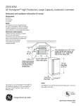
OSIRIS
Infrared Imaging System
Tel
+44 (0) 1763 250722
Fax
+44 (0) 1763 250722
E-mail [email protected]
www.opusinstruments.com
Opus Instruments Limited
28
USER MANUAL
Opus Instruments Ltd
1
5
3
Software Installation
6
4
User Interface
8
5
Calibrating the camera
13
6
Lighting
16
7
The lens F/number
19
8
Initial Setup
20
9
Taking a Picture
21
10
Reference appendices
24
32
22
11
16
2500
0
1000
2000
3000
4000
5000
6000
7000
3000
2
D epth of Field
mms
Cover—The Magdalen NG719
by kind permission of
The National Gallery London
27
O bje ct to came ra body distance
mms
Unpacking and Assembly
5500
2
5000
4
4500
Your camera
4000
1
3500
3
Depth of Field
Declaration of Conformity
6000
Page
8
Lens
F/number
CONTENTS
This device complies with Part 15 of the FCC rules. Operation is subject to
the following two conditions:
(1)
This device may not cause harmful interference.
(2)
This device must accept any interference received, including
interference that may cause undesired operation.
1200
1000
For customers in Canada
This Class A digital apparatus meets all requirements of the Canadian
Interference-Causing Equipment Regulations.
For customers in the EEC
The “CE” mark indicates that this product complies with the requirements
for safety, health, environment and customer protection.
600
0
200
400
600
800
1000
D epth of Field
mms
800
O bje ct to came ra body distance
mms
1800
1600
OSIRIS –A1
Opus Instruments Limited
50 High Street
Bassingbourn
Royston
Herts
UK SG8 5LE
Tested to comply with FCC standards
FOR OFFICE USE
1400
D epth of Field
2000
32
22
16
11
8
Lens
F/number
For customers in the USA
Declaration of Conformity
Model Number
Trade name
Address
March 2008
26
3
YOUR CAMERA
1.
2.
3.
4.
5.
6.
7.
8.
9.
Camera body
Focussing attachment
Lens (filter not shown)
USB port
Power inlet
Power switch
Coarse focus lock
Fine focus adjustment
Focus scale
4
Focus S cale R eading
against Object distance
O bje ct Distance mm
2000
Scale
to 1900
3000
4000
5000
6000
7000
8000
100
20
90
18
80
16
70
Scale
from
2000
14
60
12
50
10
40
8
30
6
20
4
10
2
0
0
25
700
900
1100
1300
1500
O bje ct Distance mm
1700
1900
UNPACKING and ASSEMBLY
3500
Your camera case holds the following parts;
Camera body
3000
Lens and
focussing
attachment
2500
Power supply
USB lead
1500
Field
mm
Field of View
2000
Instruction manual
1.
Lay the camera on its back and insert the 2 rails of the focus
attachment into the two holes in the front of the camera
ensuring that the rods push fully home and the scales are
away from the camera and facing up. When the rods are
inserted use the Allen Key in the two holes in the bottom of
the camera to tighten the two bolts by turning clockwise.
2.
Remove the black plastic cover from the bellows plate
ensuring that no dirt falls inside the camera.
3.
Slide the lens assembly onto the 2 rods and secure the lens
plate to the bellows using the 4 thumbscrews.
4.
The camera can either be stood on a flat surface or attached
to a tripod. The base has both 1/4” and 3/8” standard tripod
screw threads.
0
500
1000
1500
2000
2500
3000
3500
4000
4500
5000
Object to
camera
mm
0
500
1000
ASSEMBLY
24
5
TAKING A PICTURE
SOFTWARE INSTALLATION
INTRODUCTION
The software application files are supplied on CD rom
compressed into a
single self-installing executable
SETUP.EXE. Run this as described below to install the
application files.
INSTALLATION OF THE APPLICATION SOFTWARE
To install the software and drivers, follow the steps below:
Place the CD ROM in your CD drive
EXAMPLE 2
You have an object 600 x 400mm which has a total depth of
only a few mm. How do we set up the camera.
The largest dimension is 600mm so looking at the Field of
View graph we note that we must set the camera at least
1250mm away from the object. Let us choose 1500mm to
have a margin of error.
Looking at the Focus scale reading graph, for a distance of
1500mm we use the blue line and axes. This gives a scale
reading of 23. We set the lens to 23.
From the system Start menu, select Run
Click on the Browse button of the dialog box that opens
Click on the down arrow of the Look in drop down list of
the Browse window that opens
Looking at the first Depth of Field graph we see that at F/8
and a distance of 1500mm we have a depth of field of 10’s of
mm. We set the lens to F/8.
Select your CD ROM drive in this list
Select SETUP.EXE from the file names that appear in
the file list and then click on the Open button
Click on the OK button of the Run dialog box and then
follow the on-screen instructions.
At F/8 we will need about 250 LUX at the object.
Now we are ready to scan the object and adjust the focus
using the fine focus.
The software will then be installed into the directory that
you have specified.
6
23
TAKING A PICTURE
SOFTWARE INSTALLATION
EXAMPLE 1
You have an object 1200 x 1600mm which has a total depth
of 400mm. How do we set up the camera.
The largest dimension is 1600mm so looking at the Field of
View graph we note that we must set the camera at least
2750mm away from the object. Let us choose 3000mm to
have a margin of error.
Looking at the Focus scale reading graph, for a distance of
3000mm we use the green line and axes. This gives a scale
reading of 13. We set the lens to 13.
We need a depth of field of 120mm. Looking at the second
Depth of Field graph we see that for a depth of field of
400mm at 3000mm we need to have a lens F/number greater
than 16. We set the lens to F/16.
At F/16 we will need to have 4 times the illumination level
than at F/8 (double the light for each stop). We therefore will
need to provide about 1000 LUX at the object.
Now we are ready to scan the object and adjust the focus
using the fine focus.
INSTALLATION OF THE CALIBRATION FILES
When you first run the application, it will create a special
directory for the calibration files and copy the factory
generated calibration files into this directory. By default this
directory is C:\Documents and Settings\All Users\Application
Data\Osiris. Do not create this directory yourself otherwise it
will not be accessible to other users.
INSTALLATION OF THE DRIVER
The Osiris USB driver must be installed on the PC in order for
the PC to be able to communicate with the camera.
The driver osiris.sys is located in the root directory of the
CD. It will also be copied to the hard drive when the
application is installed. It will be copied into the <installation
directory>\usbdriver directory.
When you first connect the camera to the USB port of a PC
running Windows 2000, Windows XP or Windows Vista, and
switch on the camera, the operating system will detect that it
has been connected and open a Found New Hardware
window. Follow the on-screen instructions directing the
operating system either to the Osiris CD or to <installation
directory>\usbdriver. The operating system will find osiris.inf
and use the information in this to install osiris.sys.
Note that the driver is not signed. If you have your operating
system configured so that it will only install signed drivers
then you will need to disable this feature. Also you may need
to repeat the driver installation process if you connect the
camera to a different USB port on the same PC.
22
7
TAKING A PICTURE
THE USER INTERFACE
STARTING UP
When you start the programme the window below will appear.
Set the lighting
Setup the lighting to provide approximately 250 LUX if using
Tungsten Halogen sources and operating at F/8.
Check the Lighting Level
Select a position on the image (move mouse pointer on
screen and press SHIFT and the LEFT MOUSE BUTTON).
Hover the mouse pointer over the captured area, at the
bottom left of your screen the intensity is displayed. If the
intensity reads 100% then reduce the illumination by either
moving the lighting away from the object or by increasing the
F/number. If the number is below 50% then increase the
illumination or decrease the F/number.
Check the Focus
Ensuring your image is in focus is the most important step to
ensure high quality, high resolution images. This process
will take some time until you become practised. The focus at
the sides and top and bottom of the object will need to be
checked.
If the camera is not connected or switched on then you will
receive the message
USB interface to camera not found.
Check the camera is switched on and the USB connected
and then click INITIALISE on the CAMERA menu
If this fails then exit the programme and check the connections
and then restart the programme. Note the camera will only
operate from the USB port that was originally chosen when you
first installed the software.
If the camera is connected you will hear the camera carry out
some start-up tests. After a few seconds the camera will scan a
8
Pre-scan
Select the area of interest, to do this move the mouse to the
top left corner of the area of interest, press and hold the
SHIFT key whilst dragging the mouse to the bottom left
corner of the area of interest. This may be repeated until the
area of interest selected is correct.
FAST CAPTURE
The camera will take a fast scan (approximately 1 minute for
a full image). The focus and illumination can now be
checked.
CAPTURE AND SAVE
Click on CAPTURE and at the end of the scan if you wish to
save the image, click SAVE.
21
INITIAL SETUP
THE USER INTERFACE
Camera—Object Distance
Using the graph in the appendix select the camera object
distance for the size of your object. Remember the camera
has a square image format so take the largest object
dimension.
ALL MEASUREMENTS SHOULD BE TAKEN
FROM THE CENTRE OF THE OBJECT TO
THE FRONT OF THE CAMERA CASE
central image area and if there is sufficient light an image will
appear.
Set the nominal focus
Use the graphs in the appendix to select the focus setting and
adjust the lens. The focus scale should be read at the front of
the lens as per the diagram below. Which shows the lens set
to 32.
Read
Scale
Here
Fine
Focus
Knob
THE SCREEN
The screen consists of several areas.
The central portion of the screen is your image area.
The left hand side menu has the user controls that allow
you to capture and save images.
The menu bar at the top has functions for calibrating and
setting up the camera.
At the bottom left of the screen the intensity of the pixel
under the mouse pointer is displayed.
THE IMAGE AREA
Your Osiris camera has its scan area divided up into 64
squares or tiles as shown below – each tile is 512 x 512 pixels.
Osiris always scans a rectangle which is a whole number of
tiles wide and high.
Set the F/number
Estimate how flat is your object. For flat objects set the
camera to F/8. For non flat object use the graphs in the
appendix to select the F/number.
20
9
THE USER INTERFACE
THE LENS F/NUMBER
Varying the lens F/number
SELECTING AN AREA OF INTEREST
Move the mouse to a point on the image area. Press and
hold the SHIFT key whilst clicking with your left mouse
button. The camera will move to that position and scan the
new area. Note previously scanned areas will still remain
on the screen. To clear the screen left click your mouse on
the CLEAR SCREEN button.
In order to capture an area of interest you must first select
the area of interest. Move the mouse to a corner of your
required area of interest. Now click the left mouse button
and whilst holding the button move the mouse to the
opposite corner of your area of interest and release the
mouse button. A rectangle will be drawn on the image
area as shown below.
10
The lens F/number is set by rotating the ring on the lens.
Your lens has an F/number that can vary from 5.6 to 45 in
steps. Varying the lens F/number has 3 effects.
1.
The larger the F/number the greater the depth
of field at the object. Objects which are not flat
will require larger F/numbers to ensure that the
whole of the object is in focus. The depth of
field for different object distances and lens F/
number is given in the appendices.
2.
The larger the F/number the less light that the
camera will collect. In order to maintain the
amount of light on the detector either the
exposure time must be increased or the
illumination levels increased. An increase by
one stop (e.g. F/11—F/16) will require a factor
of 2 increase in illumination.
3.
The resolution of the camera is a function of
both the detector and the F/number. For low F/
numbers the resolution is limited by the
detector. For F/numbers greater than F/16 the
resolution is limited by the F/number. Optimum
19
LIGHTING
THE USER INTERFACE
What level of illumination?
Other sections explain the adjustments that can be made
to the exposure time and the lens F/number and the
effects that will have on the image. For the best quality
images with the camera operating at an F/8 you will need
about 250 LUX object illumination with Tungsten Halogen
lamps.
When you press CAPTURE the camera will scan the area
defined by your rectangle remembering that it will scan a
whole number of tiles. As the camera scans the image will
be displayed. At any time you may pause the capture by
pressing PAUSE/CANCEL on the screen. You can then
either RESUME the scan or change the camera setup before
restarting a new scan.
This can be equated to a required lamp power of about 10
Watts per square metre. However lamps generally spray
light over a very large angle and to achieve the required
illumination with the lamps at a sensible distance from the
object larger lamp powers will be required.
For Example
To image a 2 metre x 2 metre object the camera to object
distance will be about 4 metres. Placing the lamps 3
metres from the object and 3 metres from the camera you
will need 2x500 Watt Halogen wide angle lamps. If you
have narrow angle lamp sources (say 60 degrees) then 2
100 Watt lamps may suffice.
When SELECT ALL is pressed the whole image area will be
selected.
ZOOMING IN
At any time you can zoom into the image. Place the mouse
over the centre of where you wish to zoom and on your
keyboard press I to zoom in and O to zoom out.
CHANGING THE CAMERA SETUP
Left click the EDIT button and select EDIT PREFERENCES.
The window below will appear.
Lighting Stability
Your image will only be as good as the lighting. Variations
in the lighting during exposure will result in artefacts in the
image.
Always allow the lamps sufficient time to warm up
Take care to minimise lighting variations due to
sunlight, doors opening or people moving.
18
11
THE USER INTERFACE
LIGHTING
Your OSIRIS camera is designed to work with Halogen lighting.
If your lighting is powered directly from the mains then the
lamps will flicker very slightly at twice the mains frequency.
Though this is not visible to our eyes the camera will see this
flicker and vertical stripes will appear on the image. To
counteract this effect OSIRIS will synchronise the image
capture with the mains frequency. For most countries this will
be at either 50 or 60 Hz. If your mains frequency is different
than either of these or if your electricity supply varies by more
than a few percent in frequency then you will need to select
CUSTOM and input an exposure time. (note the exposure time
for AC supplies should be 500 divided by the frequency; ie. 10
milliseconds for 50Hz supplies and 8.3 milliseconds for 60Hz
supplies)
For most purposes two sources have been found to
provide satisfactory illumination.
Typical Illumination Geometry
With 2 sources the optimum geometry is as in the diagram
below. Though the distances Z and X are not critical it is
If the light sources are DC operated then you may select any
exposure time above 1 millisecond.
Your camera has 2 sensitivity settings. Normal use is at LOW
SENSITIVITY which gives low noise imaging.
HIGH
SENSITIVITY will require 10 times less light on the object but
will have slightly noisier images. The table below summarises
this (figures in brackets are for 60Hz mains supplies).
Normal capture under normal
light level conditions
(BEST IMAGE)
Fast capture under normal
lighting conditions
(MAY DISPLAY LIGHTING
STRIPES)
Normal capture under low light
level conditions
(SLIGHTLY NOISIER IMAGE)
Sensitivity
Exposure time
Low
10 (8.3) msec
High
1 (0.8) msec
High
10 (8.3) msec
12
best to have X as large as possible within the constraints
of the angle of light from the source. Too large a distance
Z and light is being thrown away. The angle of illumination
should be between 30 and 60 degrees.
17
LIGHTING
THE USER INTERFACE
Light Source Type
The camera is designed to be used with Tungsten Halogen
illumination as this most closely matched the camera
spectral sensitivity. Other sources that emit radiation in
within the camera’s wavelength sensitivity can be used but
will deliver a higher proportion of light outside of the
camera sensitivity and hence more heat.
The combination of low sensitivity and short exposure times
would require greater light levels without any corresponding
advantage.
Mains or DC
Mains operated lighting will fluctuate at twice the mains
frequency; I.e. if your mains frequency is 50Hz then the
light from you lamp will have a small variation with a period
of 10 milliseconds. This fluctuation will appear on the
image as vertical stripes if it is not corrected. OSIRIS can
remove this effect by having the time the detector is
integrating the light the same as light fluctuation period.
DC operated lights will allow shorter integration times and
hence shorter image capture times.
For all sources it is important that the light has had
sufficient time to warm up and stabilise before acquiring an
image. This will be typically a few minutes.
How to Illuminate
As with all imaging the captures image will only be as
uniform as the lighting of the object. A single light source
to one side of the camera will provide more illumination to
one side of the object. Two light sources placed either side
of the camera will provide more uniform illumination across
the object but will still have a minor variation vertically. An
array of sources either side of the camera will provide even
better uniformity.
16
CALIBRATING THE CAMERA
The sensor in OSIRIS has been calibrated at the factory to
allow for variations in the both the black level signal (Dark
current correction) and the white level gain (Shading
correction).
Both these calibrations should be done for each combination of
exposure time and gain that is set. If you try to run the camera
at an exposure time and gain that has not been calibrated then
you will receive the message
“A shading calibration for an exposure of
… msec can not be found. Would you like
to use an exposure calibration of …?”
The software will offer a calibration closest to the one you have
requested. If it is close then the image will have acceptable
quality otherwise the image may not be of optimum quality. You
may then receive the message
“A Dark current correction for an exposure of
… msec can not be found. Would you like
to use a dark current calibration of …?”
The software will offer a calibration closest to the one you have
requested. If it is close then the image will have acceptable
quality otherwise the image may not be of optimum quality.
13
THE USER INTERFACE
THE USER INTERFACE
If your normal mains frequency is 50Hz then the calibrations will
have been carried out and stored for 10 msec at low gain and
1msec at high gain.
If your normal mains frequency is 60Hz then the calibrations
will have been carried out and stored for 8.33 msec at low gain
and 0.83msec at high gain. This calibration needs to be carried
out for the whole camera image to adjust for variations in the
image brightness. The black level needs to be set for for each
exposure time and gain used but only needs to be carried out in
one camera position. The black level calibration will have been
measured and stored for the same conditions as the white level
calibration.
In normal use the camera will not need to be calibrated after
your initial setup.
However over time the detector
characteristics may change slightly. If your image has faint
horizontal stripes then the camera may need re-calibrating.
If you want to use different exposure times then you will need to
calibrate the camera. This is a very simple procedure.
1. Set a white matt board at a distance of between 0.5 and
1 metres from the camera with your normal illumination
set-up (see the section in this user guide on
illumination), set the lens aperture to F/8 and ensure the
image is out of focus. Check that all the image is of the
board. Adjust your lighting
2. Set the exposure time and gain that you wish to use.
3. Click on Raw pixels. Select the centre of the image and
check the intensity. Adjust the lighting until the intensity
is 80 – 90%.
4. Click on the CALIBRATE button
5. Cover the lens and select the ACQUIRE DARK
CURRENT CALIBRATION
6. Remove the lens cap and click on ACQUIRE SHADING
CORRECTION.
This operation will take several
minutes.
14
15