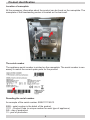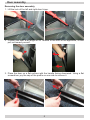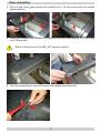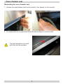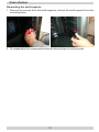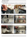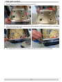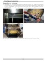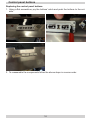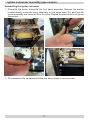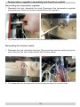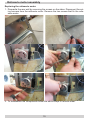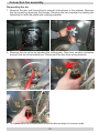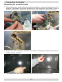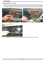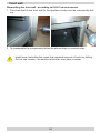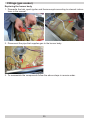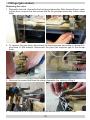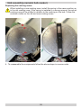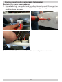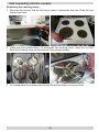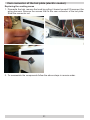
1
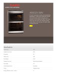
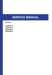
SERVICE MANUAL
Freestanding cooker 500 and 600 / Range 2013
Gas - electric
Ceramic - electric
Electric
Manual developed by:
R. Stołowski
E. Banach
R. Bedoński
Address your questions to:
[email protected]
2
Contents
1. Product identification
2. Door assembly
3. Oven chamber seal
4. Knob assembly (gas cooker)
5. Oven shelves
6. Hob (gas cooker)
7. Thermocouple (gas cooker)
8. Front panel assembly
9. Programmer
10. Control panel buttons
11. Igniter connector assembly (gas cooker)
12. Temperature regulator assembly and function switch 13. Rotisserie motor assembly
14. Convection fan assembly
15. Bottom heater
16. Convection fan heater
17. Top heater
18. Front wall
19. Fittings
20. Hob assembly (ceramic hob cooker)
21. Energy metering device (ceramic hob cooker)
22. Hob assembly (electric cooker)
23. Cam connector of the hot plate
3
4
5
8
9
10
11
13
14
15
16
17
18
19
20
21
22
23
24
25
27
29
30
31
Product identification
Location of nameplate
All the necessary information about the product can be found on the nameplate. The
nameplate of the freestanding cooker is located on the back wall.
The serial number
The appliance serial number is printed on the nameplate. The serial number is necessary to match the correct spare parts for the product.
Decoding the serial number.
An example of the serial number: 99991111136513
9999 - serial number in the batch of the product
11111 - Product Code (a unique number for each type of appliance)
365 - day of production
13 - year of production
4
Door assembly
Removing the door assembly
1. Lift the lock of the left and right door hinge.
2. Position the door at an angle of 45° relative to the front of the appliance, lift and
pull out toward yourself.
3. Place the door on a flat surface with the handle facing downward. Using a flat
screwdriver, pry the cap of the profile on one side to remove it.
5
Door assembly
4. Pull out the inner glass panel and carefully lift it. Do the same with the middle
glass panel(s).
5. Remove the screw that fastens the hinge to the inner glass profile. Pull the hinge
out of the profile.
Refer to the Annex to the SBI_001 service manual.
6. Use the screwdriver to pry and remove the glass panel bracket.
6
Door assembly
7. Remove the door handle by undoing the screws.
8. To reassemble the components follow the above steps in reverse order.
7
Oven chamber seal
Dismantling the oven chamber seal
1. Unhook the seal holders from the front wall in four places (in the corners).
2. To reassemble the components follow the above steps in reverse order.
The seal should be mounted
with the joint facing down.
8
Knob assembly (gas cooker)
1. Pry the knob's interior part, squeeze both parts together and pull toward yourself.
2. To reassemble the components follow the above steps in reverse order. Important! There is a spring between the two elements.
9
Oven shelves
Dismantling the shelf supports
1. Remove the runners from the shelf supports, unhook the shelf supports from the
mounting holes.
2. To reassemble the components follow the above steps in reverse order.
10
Hob (gas cooker)
Dismantling the hob
1. To dismantle the cover assembly open it maximally (to vertical position) and pull
it upward. Remove the two screws that fix the hob to the freestanding cooker
body.
2. Undo the screws that fix the burner bodies (two screws for each burner).
3. Gently push the burner body to the inside; pay special attention not to damage
the thermocouple and spark igniter.
11
Hob (gas cooker)
4. Gently slide the hob toward the back and lift it.
5. After dismantling the hob, remove the old seal and, after repair, install a new seal
when mounting the hob.
6. To reassemble the components follow the above steps in reverse order.
12
Thermocouple (gas cooker)
Replacing the thermocouple
1. Unhook the thermocouple from the valve. Unhook the thermocouple lock located
in the burner body, prying it with a flat screwdriver.
2. Slide the thermocouple from the burner body guide.
3. To reassemble the components follow the above steps in reverse order.
13
Front panel assembly
Dismantling the front panel
1. Dismantle the door assembly. Remove the two screws that fix the front panel to
the freestanding cooker body. The screws are located on the bottom of the panel
and are visible after opening or dismounting the door. Gently pull the panel toward yourself.
2. To reassemble the components follow the above steps in reverse order.
14
Programmer
Dismantling the programmer
1. Disconnect the wiring harness, pry and unhook the programmer from the internal
panel by pushing it to the outside.
2. To reassemble the components follow the above steps in reverse order.
15
Control panel buttons
Replacing the control panel buttons
1. Using a flat screwdriver, pry the buttons' catch and push the buttons to the outside.
2. To reassemble the components follow the above steps in reverse order.
16
Igniter connector assembly (gas cooker)
Dismantling the igniter connector
1. Dismantle the knobs, dismantle the front panel assembly. Remove the washer
located directly under the knob assembly, on the valve stem. Pry and turn the
igniter assembly and remove it from the valve. Repeat the procedure for all igniter
connectors.
2. To reassemble the components follow the above steps in reverse order.
17
Temperature regulator assembly and function switch
Dismantling the temperature regulator
1. Dismantle the hob, dismantle the knob. Disconnect the temperature regulator
wiring harness. Remove the two screws that fix the regulator.
2. To reassemble the components follow the above steps in reverse order.
Dismantling the function switch
1. Dismantle the hob, dismantle the knob. Disconnect the function switch wiring harness. Remove the two screws that fix the function switch.
2. To reassemble the components follow the above steps in reverse order.
18
Rotisserie motor assembly
Replacing the rotisserie motor
1. Dismantle the rear wall by removing the screws on the sides. Disconnect the wiring harness from the rotisserie motor. Remove the two screws that fix the rotisserie motor.
2. To reassemble the components follow the above steps in reverse order.
19
Convection fan assembly
Dismantling the fan
1. Remove the rear wall according to relevant instructions in the manual. Remove
the fan guard by removing the screws. Remove the fan propeller by holding the
fastening nut with the pliers and rotating propeller.
2. Remove the fan drive by bending the locking tab. Then turn counter-clockwise
and pull the fan drive toward you. Disconnect the fan drive wiring harness.
3. To reassemble the components follow the above steps in reverse order.
20
Bottom heater
Dismantling the bottom heater
1. Dismantle the rear wall by removing the screws on the sides. Disconnect the wiring harness from the heater. Gently remove the oven insulation, pay special attention not to damage (delaminate) the insulation. Using a flat screwdriver, gently
deflect the catches securing the heater. Slide the heater toward yourself.
2. To reassemble the components follow the above steps in reverse order.
21
Convection fan heater
Dismantling the convection heater
1. Remove the rear wall and the fan guard according to relevant instructions in the
manual. Disconnect the wiring harness from the convection fan heater. Using a
socket head wrench undo and remove the nut securing the heater assembly.
2. Inside the oven chamber, remove the screw securing the heater and pull the
heater toward yourself.
3. To reassemble the components follow the above steps in reverse order.
22
Top heater
Dismantling the top heater
1. Remove the rear wall according to relevant instructions in the manual. Disconnect the wiring harness of the top heater. Remove the nuts securing the heater to
the oven chamber. After unscrewing, remove the heater from the oven chamber.
2. To reassemble the components follow the above steps in reverse order.
23
Front wall
Dismantling the front wall - according to IS-001 service manual
1. The rivets that fix the front wall to the appliance body must be removed by drilling.
2. To reassemble the components follow the above steps in reverse order.
Install new rivets after the repair that required removal of rivets by drilling.
Do not use screws - the service technician must have a riveter.
24
Fittings (gas cooker)
Replacing the burner body
1. Dismantle the hob, spark igniter and thermocouple according to relevant instructions in the manual.
2. Disconnect the pipe that supplies gas to the burner body.
3. To reassemble the components follow the above steps in reverse order.
25
Fittings (gas cooker)
Replacing the valve
1. Dismantle the hob, dismantle the front panel assembly. After dismantling or opening the door, remove the two screws that fix the gas pipe assembly to the cooker
body.
2. To replace the gas valve, disconnect the thermocouple according to relevant instructions in this manual, disconnect the pipe that supplies gas to the burner
body.
3. Remove the screw that fixes the valve, dismantle the valve by lifting it.
4. To reassemble the components follow the above steps in reverse order.
26
Hob assembly (ceramic hob cooker)
Replacing the cooking zones
1. Remove the screws that fix the hob in order to dismantle the hob. Slide the hob
toward the back.
2. Place the hob upside-down, protect the cooking surface against scratching. Remove the screws that fix the cooking zone.
3. Press the spring that fixes the cooking zone in order to slide the cooking zone
out.
27
Hob assembly (ceramic hob cooker)
Replacing the cooking zones
When installing a new cooking zone, install the spring in the same position as
in the old cooking zone. If the spring is installed in a wrong manner, the actual
cooking zone will be shifted in relation to the marking on the hob. Follow the
numbers visible on the old and new cooking zones.
4. To reassemble the components follow the above steps in reverse order.
28
Energy metering device (ceramic hob cooker)
Replacing the energy metering device
1. Dismantle the hob, remove the knob by pulling it toward yourself. Disconnect the
wiring harness. Remove the screws that fix the energy metering device. Slide the
energy metering device out.
2. To reassemble the components follow the above steps in reverse order.
29
Hob assembly (electric cooker)
Replacing the cooking zones
1. Remove the screws that fix the hob in order to dismantle the hob. Slide the hob
toward the back.
2. Place the hob upside-down. To dismantle the cooking zone, undo the nut that
fixes the cooking zone and disconnect the wiring harness.
3. To reassemble the components follow the above steps in reverse order.
30
Cam connector of the hot plate (electric cooker)
Replacing the cooking zones
1. Dismantle the hob, remove the knob by pulling it toward yourself. Disconnect the
wiring harness. Remove the screws that fix the cam connector of the hot plate.
Slide the connector out.
2. To reassemble the components follow the above steps in reverse order.
31
Notes
..........................................................................................................................
..........................................................................................................................
..........................................................................................................................
..........................................................................................................................
..........................................................................................................................
..........................................................................................................................
..........................................................................................................................
..........................................................................................................................
..........................................................................................................................
..........................................................................................................................
..........................................................................................................................
..........................................................................................................................
..........................................................................................................................
..........................................................................................................................
..........................................................................................................................
..........................................................................................................................
..........................................................................................................................
..........................................................................................................................
..........................................................................................................................
..........................................................................................................................
..........................................................................................................................
..........................................................................................................................
..........................................................................................................................
..........................................................................................................................
..........................................................................................................................
..........................................................................................................................
..........................................................................................................................
..........................................................................................................................
..........................................................................................................................
..........................................................................................................................
..........................................................................................................................
..........................................................................................................................
..........................................................................................................................
..........................................................................................................................
..........................................................................................................................
..........................................................................................................................
..........................................................................................................................
32
Notes
..........................................................................................................................
..........................................................................................................................
..........................................................................................................................
..........................................................................................................................
..........................................................................................................................
..........................................................................................................................
..........................................................................................................................
..........................................................................................................................
..........................................................................................................................
..........................................................................................................................
..........................................................................................................................
..........................................................................................................................
..........................................................................................................................
..........................................................................................................................
..........................................................................................................................
..........................................................................................................................
..........................................................................................................................
..........................................................................................................................
..........................................................................................................................
..........................................................................................................................
..........................................................................................................................
..........................................................................................................................
..........................................................................................................................
..........................................................................................................................
..........................................................................................................................
..........................................................................................................................
..........................................................................................................................
..........................................................................................................................
..........................................................................................................................
..........................................................................................................................
..........................................................................................................................
..........................................................................................................................
..........................................................................................................................
..........................................................................................................................
..........................................................................................................................
..........................................................................................................................
..........................................................................................................................
33
Document No.:
Date prepared:
Date revised:
Date changes made:
Service Information Bulletin
SBI-0001
2013-02-15
2013-02-21
2012-07-01
Type of change:
Glass assembly frame / External glass assembly
Implementation in products:
Built-in ovens and freestanding cookers of width 500 and 600 (for products manufactured with door assembly comprising Brerr's door
hinge). No changes were made to the design of product series 608* with convex door (bulging outward)
Origin:
Until 2010-06-26 - Brerr's hinge (longer) + non-profiled U sections glued to the glass used in production.
From 2010-06-26 until 2013-01-17 - Atasan hinge (shorter) + non-profiled U sections glued to the glass used in production
Since 2013-01-17 - new profiled U section glued to the glass + Atasan hinge (shorter) used in production
New element
New element index
n/a
The assembly surface of the strip on glass
was reduced, there is a gap indicated on the
picture
n/a
Strip glued on its entire length
Obsolete element
Obsolete element index
For more efficient parts delivery, please check if the customer's appliance is with or without the gap, before ordering spare parts
Obsolete elements may be used in new products
New elements may be used in obsolete products
YES
CONDITIONALLY*
* Additional modification
In obsolete products also hinge must be replaced**
Obsolete hinge: Brerr
New hinge: Atasan
For door assembly hole plugs are added free of charge (use them with a new hinge)
Additional notes:
** When replacing door or glass assembly in products manufactured before 2010-06-26, additional two Atasan hinges must be ordered, as the originally used hinges are not
suitable for the new type glass assembly which was introduced on 2013-01-17.
Those products are labelled with serial numbers lower than: X X X X X X X X X 1 7 7 1 0
When ordering the hinge, please give the appliance serial number to select an appropriate tension of springs in hinges. Available hinges:
ATASAN DOOR HINGE - P0802A1 (2) 8042000 - Freestanding cookers 500 and freestanding cookers of 608* series
ATASAN DOOR HINGE - P0802B1 (3) 8042001 - Freestanding cookers 600 and built-in ovens / glass x2 (external and internal)
ATASAN DOOR HINGE - P0802C1 (4) 8042002 - Freestanding cookers 600 and built-in ovens / glass x3 (external, middle, internal)
ATASAN DOOR HINGE - P0802C1 (5) 8051075 - Products with pyrolysis function and selected induction cookers
When installing a glass assembly in a product manufactured before 2010-06-26, use obsolete glass suspension elements.
IS-003_EN
(06.2013)