1
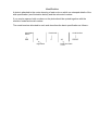
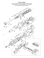
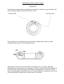
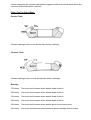
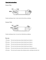
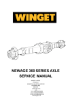
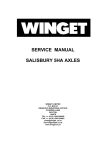
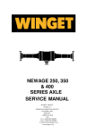
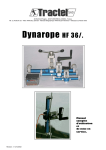
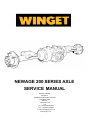
NEWAGE 200 SERIES AXLE
SERVICE MANUAL
WINGET LIMITED
PO BOX 41
EDGEFOLD INDUSTRIAL ESTATE
PLODDER LANE
BOLTON
LANCS BL4 OLS
U.K.
Tel:++44(0)1204 854650
Fax:++44(0)1204 854663
E-mail [email protected]
www.winget.co.uk
CONTENTS
INTRODUCTION
GENERAL DESCRIPTION
IDENTIFICATION
GENERAL SERVICE INFORMATION
EXPLODED VIEW/PARTS LIST
SECTION A
PINION HOUSING
SECTION B
DIFFERENTIAL ASSEMBLY
SECTION C
PLANET CARRIER ASSEMBLY
SECTION D
AXLE ARM AND HUB ASSEMBLY
SECTION E
BRAKES
SECTION F
SETTING UP CROWNWHEEL AND PINION
SECTION G
SPIRAL BEVEL GEAR TOOTH CONTACT
Section 1
INTRODUCTION
Introduction
Winget Limited gratefully acknowledge the assistance given by Newage Transmissions
Limited in the preparation of this manual, however neither Winget Limited or Newage
Transmissions can be held responsible for any errors or ommissions.
The procedures described within this manual should enable experienced service
personel to strip, repair and re-build Newage 200 series axles fitted to Winget 2B, 4B and
4S range site dumpers in a safe and competant manner. The procedures are not
intended to be used by personnel who are unfamiliar with the product or mechanically
inexperienced.
It is assumed that personnel are aware of the Health and Safety Regulations which
should be applied but the following should act as a reminder.
Whenever possible any repairs or service should be carried out in a clean environment.
If work must be carried out on site or in the field steps should be taken to ensure that dirt
or foreign materials cannot enter the assembly.
Ensure all work tools are in good condition and only use the correct tool for the job in
hand.
Always wear safety spectacles when using soft or hard faced hammers, chisels, drifts or
when using air tools. Wear safety spectacles when cleaning components or when
grinding.
Do not misuse air lines and be aware of the damage compressed air can cause if
misused.
Always make sure lifting equipment is in good condition and the Safe Working Load
exceeds the weight of the component to be lifted.
Always use suitable supports i.e. axle stands or baulks of timber in conjuction with
hydraulic jacks etc. Never rely on hydraulic jacks alone to support a machine.
Be aware of hot surface temperatures and take care when draining hot oils. Always
dispose of waste oils in accordance with local and national regulations.
Whenever possible always disconnect the battery or battery isolator when working on the
machine to prevent electrical shorts and unauthorised starting.
Refer to the operators handbook for a guide to the correct sequence for assembling
components and sub-assemblies.
Oils, fuels, silicone sealer etc can cause skin diseases if allowed to contaminate the skin.
Always apply barrier creams, wear suitable protective clothing or when contamination is
unavoidable clean the area with soap and water as soon as possible. Do not use thinners
or other solvents to clean skin.
Health and Safety is a matter of common sense. If common sense is applied correctly
the risk of accidents can be reduced.
Spares for Newage Axles fitted to Winget Equipment can only be obtained from Winget
Limited or one of our authorised distributors and not from Newage Transmissions
Limited. Always quote your machines serial number and model together with axle serial
number and model when ordering spare parts.
200 Series axles are designed to operate under arduous conditions and providing they
are regularly and correctly maintained they will provide long trouble free service.
Whilst every effort is made to ensure the contents of this manual are accurate Winget
Limited and Newage Transmissions reserve the right to alter specification without prior
notification and certain sections of this manual may then no longer apply.
Section 2
GENERAL
DESCRIPTION
General Description
The 200 Series is a double reduction drive axle with integral long life oil immersed
multiplate disc brakes.
The central casing houses the spiral bevel crownwheel and pinion assembly, the
crownwheel being mounted on a two pinion differential. The central casing also contains
the oil immersed brake assemblies and the planetary reduction gears.
The axle half shafts are fully floating and the wheel hubs run on opposed taper roller
bearings.
The approximate weight is 114kg (250lb)
Section 3
IDENTIFICATION
Identification
A plate is attached to the centre housing of each axle on which are stamped details of the
axle specification (see illustration below) and the axle serial number.
If you require spares, both numbers on the plate should be quoted together with the
machine model and serial number.
The model number allocated to each axle describes the basic specification as follows:-
Axle Model
Series
200
Fixed Pads
R
Rigid Drive
F
Code Number
14
Reduction Ratio
14.8:1
S3210
Section 4
GENERAL SERVICE
INFORMATION
General Service Information
Routine maintenance
Check
Interval
For oil leaks around joints and seals
Weekly/50 hours
Wheel nut tightness
Daily/8 hours
Hub bearing adjustment
hours
12 Monthly/1000
Axle arm/centre case nuts
Weekly/50 hours
Halfshaft securing nuts
Weekly/50 hours
Propshaft nuts and bolts
Weekly/50 hours
Brake pipe connections
Weekly/50 hours
Lubricants
The oils used must have the correct additives to be compatible with the mineral oil
braking system, therefore, only those lubricants shown below or their direct equivalents
must be used.
Mobil Fluid 422
Agricastrol As Special
Esso Torque Fluid 56 or 62
Gulf Universal Tractor Oil
Total Universal Plant Oil
Total Transmission Mp
The oil is added via the combined filler/level plug located in the face of the centre housing
on the oposite face from the input flange.
The oil capacity is approximatley 3.5 Litres (6 pints)
Greases
The areas listed below should be lubricated and packed with grease during overhauls or
repairs.
1)
Hub oil seals, between the V ring seal and hub oil seal.
2)
Input pinion oil seals.
Using one of the following greases or their equivalents:Mobil grease MP
Esso Beacon 2
Total Multis EP2
Brake Fluid
The oil immersed brakes are operated using a mineral hydraulic fluid. On no account
must a vegetable based brake fluid be used otherwise all braking system seals will be
damaged.
Whenever the brakes are serviced it is essential that the cylinder bores, pistons and
seals are cleaned before assembly and lubricated using one of the following mineral oils
or equivalent.
Total Azzola ZS46
Total Azzola ZS22
Shell Tellus 27
Mobil DTE 24
Esso Nuto H32
Liquid Sealants
On assembly the following mating surfaces should be coated as indicated. Under no
circumstances should Silicone RTV Compound be used on the Pinion Housing/Cartridge
or the Axle Arm to Case Joints.
Pinion Housing/Cartridge to Maincase
Hermatite
Axle Arm to Main Centre Housing
Hermatite
Stub Axle to Axle Arm
(Where applicable)
Hermatite
Halfshaft to Hub
Compound
Silicone RTV
Tightening Torques
Description
Torque
Differential Assembly Nuts
Kpm
5.6
(Ibft)
40
Nuts and Bolts Differential
Bearing Housing to Maincase
5.6
40
Pinion Housing to Maincase Setscrews
5.6
40
Axle Arm to Maincase Nuts
5.6
40
Halfshaft to Hub Nuts
5.6
40
Description
Hub Assembly Ring Nut
Torque
Kpm
(lbft)
14
100
Wheel Nuts 5/8 BSF
25
180
Wheel Nuts 18mm
28
200
Brake Pipe Adaptor
2.8
20
19
35
55
84
168
294
696
17
30
48
73
146
255
606
5/16
3/8
7/16
1/2
5/8
3/4
1"
515
217
124
62
40
26
829
349
200
100
65
41
23
11
7
14
NOM.
MIN.
953
402
230
115
75
47
26
13
MAX.
GRADE V
704
297
170
85
55
35
19
10
MIN.
1004
423
243
121
79
50
28
14
NOM.
1155
487
279
140
91
58
32
16
MAX.
GRADE X
NOM.
10
21
38
59
91
183
319
757
SIZE
1/4
5/16
3/8
7/16
1/2
5/8
3/4
1"
871
367
210
105
68
43
24
12
643
271
156
78
51
32
18
9
1036
437
250
125
81
52
28
14
1191
502
288
144
94
59
33
16
MAX.
NOM.
MAX.
MIN.
GRADE V
GRADE S
881
371
213
106
69
44
24
12
MIN.
1255
529
303
152
99
63
35
17
NOM.
1443
609
349
174
113
72
40
20
MAX.
GRADE X
IMPERIAL IN POUNDS-FEET (LBF-FT) COATED THREADS, ZINC & ZINC PASSIVATED
10
8
1/4
MAX.
NOM.
SIZE
GRADE S
IMPERIAL IN POUNDS-FEET (LBF-FT) PLAIN THREADS
1067
450
258
129
84
53
29
15
MIN.
853
360
206
103
67
43
23
12
MIN.
24
20
16
12
10
8
6
5
SIZE
24
20
16
12
10
8
6
5
SIZE
770
450
210
96
56
28
11
7
MAX.
570
340
160
72
40
20
8
5
MIN.
920
560
280
115
67
33
14
8
NOM.
1040
640
320
130
77
37
16
9
MAX.
GRADE 10.9
800
480
240
100
57
29
12
7
MIN.
1171
677
347
140
80
40
17
10
NOM.
1347
779
399
161
92
47
19
11
MAX.
GRADE 12.9
868
502
257
104
59
30
12
7
NOM.
998
577
296
119
68
34
14
8
MAX.
GRADE 8.8
737
426
219
88
50
25
10
6
MIN.
1220
706
362
146
84
42
17
10
NOM.
1403
811
416
168
96
48
20
12
MAX.
GRADE 10.9
1037
600
307
124
71
36
15
9
MIN.
1464
847
434
175
100
51
21
12
NOM.
1684
974
499
201
115
58
24
14
MAX.
GRADE 12.9
METRIC IN NEWTON/METRES (Nm) COATED THREADS, ZINC & ZINC PASSIVATED
694
401
206
83
48
24
10
6
NOM.
GRADE 8.8
METRIC IN NEWTON/METRES (Nm) PLAIN THREADS
NEWAGE TRANSMISSIONS: TORQUE VALUES FOR FASTENERS WITH CLEAN & DRY THREADS
1244
720
369
149
85
43
18
10
MIN.
995
576
295
119
68
34
14
8
MIN.
Section 5
EXPLODED VIEWS
AXLE 200RF
Type 3210 shown, number of brake plates and disc’s
is dependant on the Axle Code No, i.e 3213 axles
have fewer brake plates and disc’s
AXLE 200RF
Description
Item No
Qty
AXLE, type 200RF14S3210 shown
Bevel Wheel Housing & Pinion Assembly
1
2
3
4
5
6
7
8
9
10
10
10
HOUSING, pinion
BEVEL WHEEL & PINION, not available as separate items
FLANGE, input, assy. ( with item 6)
WASHER
NUT
COVER, seal (part of item 3)
BEARING
SPACER
SEAL, oil
SHIM, 0.25mm
SHIM, 0.30mm
SHIM, 0.40mm
1
1
1
1
1
1
2
1
2
AR
AR
AR
Differential assembly
15
16
17
18
19
20
21
22
23
24
25
CASING, L.H., differential
CASING, R.H., differential
WHEEL, differential
PINION, differential
WASHER, thrust, differential wheel
WASHER, thrust, differential pinion
SPIDER
PIN, spirol
STUD
STRIP, locking
NUT
1
1
2
2
2
2
1
2
8
4
8
Planet Carrier assemblies
30
31
32
33
34
35
36
37
CARRIER, planet gears
GEAR, planet
PIN, planet gears
SPACER, axle shaft
CIRCLIP
BEARING, needle roller
WASHER, thrust
DOWEL
2
6
6
2
2
6
12
6
Hub assemblies
45
46
47
48
49
50
51
HUB
STUD, wheel
BEARING, hub inner
SEAL, 'V' ring
SEAL, oil
SLEEVE
HOUSING, oil seal
FOR PART NUMBERS REFER TO RELEVANT PARTS MICROFICHE OR OPERATORS HANDBOOK
2
12
2
2
2
2
2
AXLE 200RF
Type 3210 shown, number of brake plates and disc’s
is dependant on the Axle Code No, i.e 3213 axles
have fewer brake plates and disc’s
AXLE 200RF
Description
Item No
Qty
AXLE, type 200RF14S3210 shown
Hub assemblies, continued
52
53
54
55
56
57
58
59
CIRCLIP
SPACER
BEARING, hub outer
SPACER
WASHER, locking
LOCKNUT
STUD
NUT, nylon insert
2
2
2
2
2
2
16
16
Main casing
60
61
62
63
64
65
66
67
68
69
70
71
72
73
74
75
76
77
CASING, main
PISTON, brake
SEAL, 'O' ring
SEAL, 'O' ring
NUT
HOUSING, bearing
PLATE, locking
SCREW
NUT
DOWEL
ADAPTOR, brake pipe
SCREW, set
WASHER, spring
SEAL, bonded
VALVE, breather
PLUG, socket
VALVE, brake bleeding
BEARING, cup & cone kit
1
2
2
2
2
2
2
6
6
2
4
12
12
4
1
2
1
2
General parts
80
81
82
83
84
85
86
SHAFT, axle
DOWEL
ANNULUS
SPACER
PLATE, brake
PLATE, disc
GEAR, sun
2
4
2
2
4
4
2
The number of Brake Disc's and Plates is dependant on the Axle Code Number I.e. 3213 axles have fewer disc's
and plates fitted
Axle arms
90
91
92
93
CASING, axle arm
STUD
NUT, nylon insert
SHIELD
100
NUT, wheel
FOR PART NUMBERS REFER TO RELEVANT PARTS MICROFICHE OR OPERATORS HANDBOOK
2
20
26
2
12
Section A
PINION HOUSING
Servicing the Pinion Housing Assembly
Section A
Place a suitable container below the axle drain plug underneath the centre housing,
remove the plug and drain the oil. Dispose of the oil safely in accordance with local
bylaws and national regulations.
Remove the setscrews securing the pinion housing to the centre casing and lift off the
assembly. The housing is located on dowels and will require carefully prising apart from
the centre casing using a pry bar or other suitable tool.
Prevent the flange from turning and undo and remove the self locking nut and flat washer
securing the flange to the pinion, using a suitable puller or drift, remove the flange and
gently drift the pinion shaft out through the housing. Take care to avoid damaging the
gear teeth, splines or threads. Prise the oil seals out of the housing, slide the old
collapsed spacer off the shaft and discard the spacer.
Note:- A new spacer should always be fitted.
Inspect the bearings for wear or damage, check the teeth on both the crownwheel and
pinion and make a visual check through the differential of the “wheels”. If the front
bearing race on the pinion shaft needs replacing use a suitable bearing puller to avoid
damaging either the shaft or the shim pack sandwiched between the pinion head and
bearing. If the outer cones require replacing thay can easily be drifted out of each end of
the housing.
Important:- If new pinion bearings are fitted check the crownwheel/pinion backlash, see
Section F “Crownwheel/Pinion Set up” If a new pinion or housing is being fitted refer to
Section F before proceeding any further.
To reassemble the housing reverse the above procedure fitting a new collapsible spacer,
install the pinion shaft through the innermost bearing cone and fit the rear bearing over
the pinion shaft. Carefully fit the new oil seals and pack with one of the recommended
greases. Refit the flange, coat the inner surface of the flat washer with silicone sealer
and loosely refit the washer and self locking nut.
Prevent the flange from turning and tighten the nut until the spacer begins to collapse and
all the end float between the pinion bearings is taken up, but without pre-loading the
bearings.
Slowly continue to tighten the nut, frequently checking the preload, until a preload of 610kg (13.2-22lbs) for new bearings or 3-6Kg (6.61-13.2lbs) for used bearings is obtained.
The preload is measured by winding a length of string round the flange and measuring
the load required to turn the flange with a spring balance. Care should be exercised
when tightening the pinion nut otherwise the required preload will quickly be exceeded.
If the old bearings have been reused coat the mating surfaces of the centre casing and
pinion housing with the recommended sealant and refit the housing to the axle.
If new bearings have been fitted refer to Section F making a note of the pinion preload
setting as it will be required later
Refit the drain plug and tighten, remove the combined filler/level plug located midway up
the face of the centre housing and fill the axle with one of the recommended oils. Refit
and tighten the level plug.
Section B
DIFFERENTIAL
ASSEMBLY
Servicing the Crownwheel and Differential Assembly
Section B
Refer to sections A,C,D and E and remove the pinion housing, axle arm, planet carrier
and brakes.
Undo the nuts and bolts securing the bearing housings and withdraw the bearing
housings. The housings are provided with threaded holes into which jacking screws can
be inserted to aid removal of the housing (unless new differential bearings are to be fitted
do not disturb the position of the bearing adjusting nuts with the bearing housings). The
differential/crownwheel assembly can be removed through the pinion housing opening in
the centre case. Mark the centre casing so that the differential assembly is correctly reassembled into the same end of the centre casing. (Assembling the crownwheel into the
opposite end of the centre casing from which it was removed will result in the rotation of
the axle being reversed).
Free the locking washers and undo the nuts securing the crownwheel to the differential,
remove the crownwheel and pull the two halves of the differential apart. To strip the
differential gears drift out the dowel pin and push out the spider.
Examine the bearings, wheels, pinions, thrust washers, spider and crownwheel for wear
or damage and replace as necessary.
Assemble in reverse order ensuring that no dirt or foreign objects enter the assembly and
replace the spring dowel. Align any indent marks on the differential casing halves, refit
the crownwheel, fit new lockwashers, torque up the nuts and bend over the lockwashers.
If new differential bearings have been fitted it is necessary to check both the bearing
preload and the crownwheel/pinion backlash as described in section F.
If the bearings are not replaced the bearing housings should be fitted in their original
position without turning the adjusting ring nuts and there is then no need to recheck either
the backlash or preload. Secure the ring nuts with the locking tabs and re-torque the nuts
and bolts securing the bearings housings.
Refer to sections A, C,D and E and reassemble the axle.
Refill the axle with oil.
Section C
PLANET CARRIER
ASSEMBLY
Servicing the Planet Carrier Assembly
Section C
To gain access to the planet carrier remove the axle arm as described in section D.
Remove the shield and carefully lift out the planet carrier without disturbing the sungear.
Check the teeth on both the annulus and sun gear for wear or damage. Check the planet
gear for wear or damage. Check the planet gears within the planet carrier, the gears
should run freely on the pins without excessive radial play.
To replace the planet gears, pins or bearings, drift the small spring dowel pins which
retain the planet pins into the centre of the pins and lightly drift the planet pins out of the
carrier. The axle shaft thrust washer is retained by a circlip which can be removed to
allow inspection of the washer.
Before re-assembling the unit remove the old spring dowels from the planet pins and
ensure new spring dowels are fitted on assembly.
If necessary the annulus which is retained in the casing by dowels can be withdrawn. If
the annulus is replaced the dowels should also be replaced, ensure the annulus is fitted
squarely into the case on assembly.
Locate the planet carrier back in the centre casings engaging the teeth on the annulus
and sun gear. Refit the shield.
Refit the axle arm assembly as described in section D.
Remove the combined filler/level plug and top up the axle with oil.
Section D
AXLE ARM & HUB
ASSEMBLY
Servicing the Axle Arm and Hub Assembly
Section D
The hub assembly and halfshaft can be serviced with the axle still in situ on the machine,
however, it is recommended that the axle be removed from the machine before the axle
arm is removed.
The Hub Assembly
Remove the self locking nuts securing the halfshaft to the hub and withdrawn the shaft.
(A drip tray placed below the hub will catch any oil which runs from the hub). Inspect the
splines for wear or damage and the shaft for signs of twist or distortion.
Straighten the locking tabs on the lockwasher securing the ring nut, undo the the ring nut
and remove the nut, lockwasher and spacer. The hub can now be withdrawn off the
opposed taper roller bearings.
Remove the V seal on the circumference of the rear of the hub, prise out the oil seal and
lift out the rear most bearing race, inspect the bearings for damage or wear and replace if
necessary. The cones can be simply drifted out of the hub, however, ensure that
replacements are square to the bores before refitting. The replacement oil seal must be
packed with grease and the V ring seal lubricated with a little oil or grease. (A new oil
seal must be fitted regardless of visual condition).
If the oil seal housing is damaged or the seal contact area worn it can be drifted off the
axle arm. When fitting the replacement care must be taken not to damage the oil seal
contact area or distort the housing. Apply “loctite” grade 601 or equivalent to both the
axle arm and seal housing mating surfaces before assembly.
To reassemble the hub reverse the procedure, lightly oil the V seal and bearings before
reassembly, fit a new lockwasher.
To Adjust the Hub Bearings
Tighten the ring nut upto a torque of 14Kpm (100lbft). Turn the wheel hub in each
direction at least three times to ensure the bearings have correctly “seated” in and recheck the torque (this operation should be repeated until the locknut no longer turns
when rechecking the torque). Slacken the ring nut back a distance equal to 1 tab of the
lockwasher then turn down a tab into the nut to secure the ring nut in place.
Coat the mating surfaces of the hub and halfshaft with the recommended sealant. Refit
the halfshaft, it may be necessary to turn the hub slightly to engage the splines on the
halfshaft with the planet carrier within the axle case. Torque up the self locking nuts.
Remove the combined filler/level plug and top up the axle oil.
Axle Arm Removal
It is recommended that the axle is removed from the machine before the axle arm is
removed.
Drain the oil from the axle as described under section A, whilst it is possible to remove
the axle arm with the halfshaft in place it is strongly recommended that the halfshaft be
removed as previously described.
Support the weight of the axle arm and remove the ring of self locking nuts round the
flange of the axle arm. (Place a drip tray below the axle and case to catch any oil which
may run out). Withdraw the axle arm taking care not to lose the shield fitted in front of the
planet carrier, or dislodge the planet carrier.
Reverse the procedure to reassemble, coating the mating surfaces of the axle arm and
casing with the recommended sealant.
Torque up the self lock nuts. Remove the combined filler/level plug and top up the axle
oil.
Section E
BRAKES
Brakes
Section E
Note the brakes operate on a mineral hydraulic fluid. On no account must a vegetable
based brake fluid be used otherwise all braking system seals will be damaged.
To gain access to the brake components it will be necessary to refer to sections D and C
and remove the axle arms and planet carriers.
Withdraw the sun gears, annulus and brake spacer plate, lift out the brake friction discs
and brake fixed plates (plain). Withdraw the brake piston from the cylinder machined into
the case and remove the seals. The brake piston seals should be replaced even if
visually in good condition, ensure replacement seals are suitable for use with mineral
hydraulic fluid.
Examine all parts for wear or damage, under normal operating conditions the brake
plates should last several years, but should be replaced if blued, distorted or badly
scored or the wear exceeds the limits given below.
Blueing of the brake plates indicates that the brakes have been overheating and slipping.
Both sets of plates, plain and sintered bronze, should be replaced and the piston seals
renewed.
Distortion normally occurs in conjuction with blueing and again indicates that the brakes
have been overheating and slipping. Both sets of plates, plain and sintered bronze
should be replaced and the piston seals renewed.
Scoring of the plates indicates that there are loose particles or foriegn material
suspended in the oil. The axle casing should be thoroughly cleaned out and if necessary
the source of the particles or material should be investigated. Both sets of plates, plain
and sintered bronze should be replaced and the axle refilled with clean oil.
Wear, if the sintered groove of the bronze brake disc is worn down to a depth of .025
inch, 0.6mm or less, then the plates have reached the end of their working life and should
be replaced. Care should be taken when examining the plain brake plates for over a long
period of operation these can show a greater degree of wear than the sintered bronze
disc. Do not assume because the bronze disc is well within the wear limits that all the
brake plates are in an acceptable condition. Replacing the plain brake plates may
prolong the working life of the brakes and restore their efficiency.
Lubricate all the components with one of the recommended mineral oils, carefully refit the
brake piston taking care not to “nip” the “O” rings.
Refit the brake plates into the axle ensuring that a plain fixed plate is installed first up
against the brake piston, (note the fixed discs locate on the dowels in the walls of the
case), followed by a friction disc, alternate the disc's ensuring a plain fixed disc is
between each friction disc, ensure that the last plate fitted is a friction disc which will butt
up to the brake spacer plate when fitted.
Align the splines and oil feed holes in the friction disc's and insert the sun gear through
the disc's, ensure it engages fully into the differential.
Refit the brake spacer plate locating over the dowels in the walls of the case. Install the
annulus gear ensuring it is aligned squarely with the case and dowels. Refit the planet
carrier engaging the teeth with both the annulus and sun gear, refit the shield.
Refit the axle arm as described in section D.
Remove the combined filler/level plug and top up the axle oil.
Section F
SETTING PROCEDURE
CROWNWHEEL &
PINION
Setting up the Crownwheel and Pinion
Section F
A)
When a new Spiral bevel Pinion is fitted.
Note the mounting distance “M D” stamped on the front faces of the old and new bevel
pinion's.
The shim thickness used with old pinion which is placed between the head of the pinion
and the front bearing race must be adjusted to suit the pinion as follows:1)
If the new “MD” is less than the old one increase the thickness of the
shim pack by the difference.
2)
If the new “MD” is more than the old one decrease the thickness of the shim
pack by the same amount.
Assemble the pinion into the housing and preload the bearings as described in Section A.
B)
When old “MD” is not available or a New Pinion Housing is fitted.
Fit the front (inner) bearing assembly into the pinion housing and sit the assembly on a
flat inspection surface, bearing down, apply a downward force to the housing directly
above the bearing whilst rotating the housing to ensure that the bearing is correctly
seated.
Accurately measure the distance between the inspection surface and the underside of
the pinion housing mounting flange i.e. mating suface. This is dimension “A”.
Add this dimension “A” to the dimension “MD” stamped on the front face of the pinion and
subtract the total from the constant 98.67, the remainder is the shim thickness required.
Assemble the pinion as described in Section “A” and preload the bearings.
With the crownwheel and differential assembled into the centre case as described in
Section “B” fit the assembled pre-loaded pinion housing assembly on to the case
retaining with two set screws.
Tighten the differential bearing ring nuts to take up any end float in the bearings and
lightly preload the bearings. Continue to adjust the ring nuts until the correct backlash is
obtained between the teeth on the crownwheel and pinions.
1310 Hardy Spicer 4 bolt flange 0.22-0.30mm
The backlash is best checked via a dial gauge indicator clock located against a drive
flange hole or located against the head of a nut and bolt which is secured in one of the
holes within the flange.
Equally tighten both ring nuts by the same amount to give the correct bearing preload (it
is important that the correct backlash is maintained). The preload is measured by
winding a length of string round the pinion flange and measuring the load required to turn
the flange with a spring balance. The preload for the differential bearings must be added
to the preload figures obtained for the pinion bearings in section “A”.
Additional Differential
Bearing Preload
New Bearings
1.0-2.0KG
(2.20-4.4lbs)
Old Bearings
0.5-1.0KG
(1.10-2.20lbs)
After setting the preload for the differential bearings recheck the crownwheel/pinion
backlash.
Remove the pinion housing and brush some “Engineers Blue” onto a few crownwheel
teeth and refit the pinion housing. Rotate the pinion flange a few complete rotations in
both directions and remove the housing. Examine the contact markings on both flanks of
the crownwheel teeth and compare the markings to the illustrations in section “G” or the
original factory markings.
If the marking is different, refer to the notes in Section “G” Spiral Bevel Tooth Contact and
make the necessary adjustments.
Secure the adjusting ring nuts with the locking devices and reassemble the remainder of
the axle as described in Sections A, C, D, and E.
Remove the combined filler/level plug and top up the axle with oil.
Section G
SPIRAL BEVEL GEAR
TOOTH CONTACT
Spiral Bevel Gear Tooth Contact
Section G
The illustration shown below is intended as a reminder to those who are unfamiliar with
the terminology applied to Spiral Bevel Gear Teeth
Convex Flank
Concave Flank
The markings on a crownwheel which is correctly meshed with the pinion should
resemble those shown on the illustration below:-
Although the contact point on both flanks of the teeth may vary slightly, generally
speaking when correctly setup the markings on both the convex and concave flanks will
be in the centre of the tooth form and can still be considered to be correct if, on both
flanks, the markings are towards the toe or if crossed slightly e.g. towards the toe on the
convex flank and the heel on the concave flank or vice-versa.
If when comparing the contact markings they appear similar to the illustrations below the
corrective action indicated is required.
Pinion Too Far Out of Mesh
Convex Flank
Contact markings closer to toe and tip than factory markings
Concave Flank
Contact markings closer to heel and tip than factory markings.
Remedy:175 series
Re-check and increase shims behind head of pinion.
200 series
Re-check and increase shims behind head of pinion.
210 series
Re-check and increase shims behind head of pinion.
220 series
Re-check and increase shims behind head of pinion.
360 series
Re-check and increase shims behind pinion front bearing cone.
410 series
Re-check and decrease shims between pinion cartridge and axle case.
Pinion Too Far into Mesh
Convex Flank
Contact markings closer to heel and root than factory markings
Concave Flank
Contact markings closer to toe and root than factory markings.
Remedy:175 series
Re-check and decrease shims behind head of pinion.
200 series
Re-check and decrease shims behind head of pinion.
210 series
Re-check and decrease shims behind head of pinion.
220 series
Re-check and decrease shims behind head of pinion.
360 series
Re-check and decrease shims behind pinion front bearing cone.
410 series
Re-check and increase shims between pinion cartridge and axle case.