1
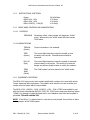
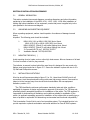
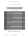
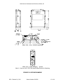
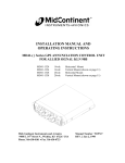
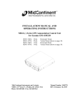
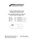
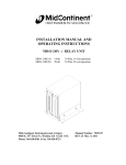
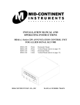
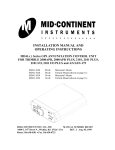
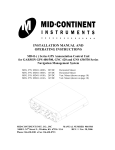
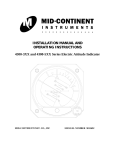
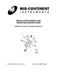
INSTALLATION MANUAL AND OPERATING INSTRUCTIONS MD41-1000 SERIES TERRAIN AWARENESS ANNUNCIATION CONTROL UNIT FOR GARMIN TAWS SYSTEMS MD41-1028 MD41-1038 MD41-1028(5V) MD41-1038(5V) MD41-1024 MD41-1034 28vdc 28vdc 28vdc 28vdc 14vdc 14vdc Horizontal Mount Vertical Mount (shown on page 12) Horizontal Mount Vertical Mount (shown on page 12) Horizontal Mount Vertical Mount (shown on page 12) Mid-Continent Instruments and Avionics 9400 E. 34th Street N., Wichita, KS 67226 USA Phone 316-630-0101 Fax 316-630-0723 Manual Number 9015308 REV. C October 28, 2013 Mid-Continent Instruments and Avionics, Wichita, KS FOREWORD This manual provides information intended for use by persons who, in accordance with current regulatory requirements, are qualified to install or repair this equipment. If further information is required, please contact: Mid-Continent Instruments and Avionics Attn: Customer Service Dept. 9400 E. 34th ST North Wichita, KS 67226 USA Phone 316-630-0101 Fax 316-630-0723 We welcome your comments concerning this manual. Although every effort has been made to keep it free of errors, some may occur. When reporting a specific problem, please describe it briefly and include the manual part number, the paragraph/figure/table number, and the page number. Send your comments to: Mid-Continent Instruments and Avionics Attn: Technical Publications 9400 E. 34th ST North Wichita, KS 67226 USA Phone 316-630-0101 Fax 316-630-0723 Copyright 2003 Mid-Continent Instruments and Avionics REV. C October 28, 2013 Manual Number 9015308 2 of 18 Mid-Continent Instruments and Avionics, Wichita, KS Revision Detail ECO 6051 Rev. N/R A Date 04/22/04 01/21/05 B C 07/02/12 10/28/13 REV. C October 28, 2013 Detail Complete issue Added “otherwise connect pin 7 to bright/dim switch on aircraft dimming bus” to note 2 of fig. 3-3 and 3-4. Removed schematics, Figure 3.5 Updated Technical Specifications to include compatible Garmin TAWS Systems Manual Number 9015308 3 of 18 Mid-Continent Instruments and Avionics, Wichita, KS TABLE OF CONTENTS SECTION 1 1.1 1.2 1.2.1 1.2.2 1.2.3 1.2.4 1.2.4.1 1.2.4.2 1.2.5 GENERAL DESCRIPTION INTRODUCTION SPECIFICATIONS, TECHNICAL PHYSICAL CHARACTERISTICS ENVIRONMENTAL CHARACTERISTICS SPECIFICATIONS, ELECTRICAL FRONT PANEL CONTROLS AND ANNUNCIATIONS CONTROLS ANNUNCIATIONS EQUIPMENT LIMITATIONS SECTION 2 2.1 2.2 2.3 INSTALLATION CONSIDERATIONS COOLING EQUIPMENT LOCATION ROUTING OF CABLES SECTION 3 3.1 3.2 3.3 3.4 INSTALLATION PROCEDURE GENERAL INFORMATION UNPACKING AND INSPECTING MOUNTING THE MD41-( ) INSTALLATION LIMITATIONS SECTION 4 4.1 4.2 POST INSTALLATION CHECKOUT PRE-INSTALLATION TEST OPERATING INSTRUCTIONS SECTION 5 5.1 5.2 5.3 5.4 5.5 5.6 5.7 5.8 5.9 INSTRUCTIONS FOR CONTINUED AIRWORTHINESS INTRODUCTION CONTROL, OPERATION INFORMATION MAINTENANCE INSTRUCTIONS TROUBLESHOOTING INFORMATION REMOVAL AND REPLACEMENT INFORMATION DIAGRAMS SPECIAL INSPECTION REQUIRMENTS SPECIAL TOOLS OVERHAUL PERIOD REV. C October 28, 2013 Manual Number 9015308 4 of 18 Mid-Continent Instruments and Avionics, Wichita, KS FIGURE 3.1 3.2 3.3 3.4 LIST OF ILLUSTRATIONS SCHEMATIC PINOUT, 25 PIN DSUB OUTLINE DRAWING WIRING DIAGRAM, MD41-1024, -1034 WIRING DIAGRAM, MD41-1024, -1034, -1028, -1038, -1028(5v), -1038(5V) APPENDIX ENVIRONMENTAL QUALIFICATION FORM REV. C October 28, 2013 Manual Number 9015308 5 of 18 Mid-Continent Instruments and Avionics, Wichita, KS SECTION 1: GENERAL DESCRIPTION 1.1 INTRODUCTION The MD41-1024, -1034, -1028, -1038 is a compact, self -contained Annunciation and Control unit. The fully integrated, control unit provides annunciation and mode selection for TAWS (Terrain Awareness Warning System). It combines all the necessary functions required to interface a wide range of TAWS systems for FAA approval. Other features include dual 20,000 hour lamps used for all annunciations, internally lighted selection switches and choice of manual or automatic photocell dimming. An external annunciation dimming adjustment is provided for balancing low level light conditions. 1.2 SPECIFICATIONS, TECHNICAL Mid-Continent Instruments Co., Inc. certifies that the model MD41-( ) series, Annunciation Control Unit has been tested to and meets or exceeds the functional and environmental requirements of the following FAA Technical Standard Order (TSO): FAA/TSO-C151a: TERRAIN AWARENESS AND WARNING SYSTEM We also certify we meet the requirements of Part 21, Subpart 0 of the Code of Federal Regulations. The MD41-( ) series, Annunciation Control Unit conforms to all pertinent documented design and internal manufacturing standards. This includes, but is not limited to: component drawings, specifications, testing criteria, inspection requirements, quality processes, manufacturing instructions, and handling procedures. It shall be manufactured in accordance with Mid-Continent Instruments FAA-approved Production Approval HolderQuality System Manual, Revision M, dated April 14, 2011 or later. The MD41-10XX series complies with the manufacturers’ specifications and has been verified and approved for use with the following systems: Mid-Continent Instruments and Avionics Model Number(s): Designed for use with TAWS System: MD41-1028 MD41-1028(5V) MD41-1038 MD41-1038(5V) MD41-1024 MD41-1034 Manufacturer: Garmin International Model: Part Numbers: GXX500 Series REV. C October 28, 2013 GPS 500 011-00863-00 011-00863-01 011-00863-10 011-00863-11 Manual Number 9015308 6 of 18 Mid-Continent Instruments and Avionics, Wichita, KS GNS 530 011-00940-00 011-00940-01 011-00940-10 011-00940-11 011-00940-31 GNS 530A 011-00864-00 011-00864-01 011-00864-10 011-00864-11 Model: Part Numbers: GTN 6XX/7XX Series GTN 6XX 011-02254-00 011-02255-00 011-02256-00 011-02256-50 GTN 7XX 011-02281-00 011-02282-00 011-02282-50 1.2.1 PHYSICAL CHARACTERISTICS Mounting: Width: Height: Depth: Weight: 1.2.2 Panel 2.75 Inches 0.80 Inches 3.22 Inches 0.50 lbs. ENVIRONMENTAL CHARACTERISTICS TSO Compliance: Applicable Documents: TSO C151a RTCA DO-160D Operating Temperature Range: Humidity: Altitude Range: -55C to +70C 95% Non-Condensing 0 to 55,000 ft Operational Shock: Rigid Mounting, 6 G Operational 20 G Crash Safety REV. C October 28, 2013 Manual Number 9015308 7 of 18 Mid-Continent Instruments and Avionics, Wichita, KS 1.2.3 SPECIFICATIONS, ELECTRICAL Design MD41-1024, -1034 MD41-1028, -1038 MD41-1028(5V), -1038(5V) 1.2.4 All Solid State 0.30 Amps 0.40 Amps 0.42 Amps FRONT PANEL CONTROLS AND ANNUNCIATIONS 1.2.4.1 CONTROLS TERR/INHB Momentary switch, when pressed, will toggle the 'Inhibit' mode. When active, the 'Inhibit' mode will inhibit certain TAWS alerts. 1.2.4.2 ANNUNCIATIONS TERR/NA (Amber) Terrain information is not available. TERR (Amber) The current flight trajectory brings the aircraft in close proximity to the terrain. Extreme caution should be exercised. PULL UP (Red) The current flight trajectory brings the aircraft in extremely close proximity to the terrain. The aircraft is in imminent danger and actions should be taken to rectify the situation. TERR/ INHB (White) The TAWS system has been placed in the 'Inhibit' mode. 1.2.5 EQUIPMENT LIMITATIONS The MD41-1000 series control units contain specific dash numbers to be used with various Terrain Awareness Warning Systems. The installer must match the correct controller part number with the system that is being installed. The MD41-1028, -1028(5V), -1038, -1038(5V), -1024, -1034 is TSO’D and certified for use with the Garmin International GNS 500, 500A, 530, 530A Terrain Awareness Warning System (TAWS). Any attempt to install the listed units in an installation other than above system is prohibited. This will void the TSO. NOTE: If the MD41-( ) is disconnected or removed from the aircraft, there will be no effect in the operation of the TAWS system. REV. C October 28, 2013 Manual Number 9015308 8 of 18 Mid-Continent Instruments and Avionics, Wichita, KS 1.2.7 MAJOR COMPONENTS This system is comprised of one major component, the MD41-1000 series TAWS Annunciation Control Unit SECTION 2 INSTALLATION CONSIDERATIONS 2.1 COOLING No direct cooling is required. As with any electronic equipment, overall reliability may be increased if the MD41-1024, -1034, -1028, -1038 is not located near any high heat source or crowded next to other equipment. Means of providing a gentle airflow will be a plus. 2.2 EQUIPMENT LOCATION The MD41-1028 must be mounted as close to the pilot’s field of view as possible. Please reference the TAWS installation manual for approved locations. The unit depth, with connector attached, must also be taken into consideration. 2.3 ROUTING OF CABLES Care must be taken not to bundle the MD41-1024, -1034, -1028, -1038 logic and low level signal lines with any high energy sources. Examples of these sources include 400 HZ AC, Comm., DME, HF and transponder transmitter coax. Always use shielded wire when shown on the installation print. Avoid sharp bends in cabling and routing near aircraft control cables. REV. C October 28, 2013 Manual Number 9015308 9 of 18 Mid-Continent Instruments and Avionics, Wichita, KS SECTION 3 INSTALLATION PROCEDURES 3.1 GENERAL INFORMATION This section contains interconnect diagrams, mounting dimensions and other information pertaining to the installation of the MD41-1024, -1034, -1028, -1038. After installation of cabling and before installation of the equipment, ensure that power is applied only to the pins specified in the interconnect diagram. 3.2 UNPACKING AND INSPECTING EQUIPMENT When unpacking equipment, make a visual inspection for evidence of damage incurred during shipment. The following parts should be included: 1. 2. 3. 3.3 MD41-1024 (14V) or MD41-1028 (28V) Horiz. Mount MD41-1034 (14V) or MD41-1038 (28V) Vert. Mount MD41-1028(5V), (28volt) 5 volt button lighting Horiz. Mount MD41-1038(5V), (28volt) 5 volt button lighting Vert. Mount J1 Connector Kit (25 pin). MCI P/N 7014517 Installation Manual. MCI P/N 9015308 MOUNTING THE MD41-( ) Avoid mounting close to heater vents or other high heat sources. Allow a clearance of at least 3 inches from back of unit for plug removal. The indicator is secured in place behind the panel since it is designed for rear mount only. Make a panel cutout as shown in Figure 3-2. Secure the indicator in place with two 4-40 x 3/8 flat head Phillips drive screws. 3.4 INSTALLATION LIMITATIONS Wire the aircraft harness according to figure 3-3 or 3-4. Use at least 24 AWG wire for all connections. Avoid sharp bends and routing cable near high-energy sources. Care must be taken to tie the harness away from aircraft controls and cables. Also see equipment limitations, section 1.2.5. “The TSO identifies the minimum performance standards, tests and other conditions applicable for issuance of design and production approval of the article. The TSO does not specifically identify acceptable conditions for installations of the article. The TSO applicant is responsible for documenting all limitations and conditions suitable for installation of the article. An applicant requesting approval for installation of the article within a specific type or class of product is responsible for determining environmental and functional compatibility.” This Annunciation Control Unit is part of an incomplete system. The intended function is to provide required or optional annunciation and mode selection for Class B TAWS systems. REV. C October 28, 2013 Manual Number 9015308 10 of 18 Mid-Continent Instruments and Avionics, Wichita, KS Rear View of J1 Mating Connector PIN 1 2 3 4 5 6 7 8 9 10 11 12 13 14 15 16 17 18 19 20 21 22 23 24 25 PIN NAME ANNUNCIATOR FULL BRIGHT #1 ANNUNCIATOR FULL BRIGHT #2 TERRAIN WARNING BRT/DIM INTERNAL DIMMING PROGRAM #1 TERRAIN CAUTION ANNUNCIATE* IN TERRAIN TEST* IN ANNUNCIATOR DIMMING IN 28 V PANEL LIGHTING BUS HI PANEL LIGHTING BUS LO TERRAIN NOT AVAILABLE ANNUNCIATE IN TERRAIN PULL UP ANNUNCIATE* IN INTERNAL DIMMING PROGRAM #2 28 V AIRCRAFT POWER SPARE SPARE SPARE SPARE SPARE TAWS ANNUNCIATE INHIBIT * IN TAWS INHIBIT * OUT AIRCRAFT GROUND AIRCRAFT GROUND AIRCRAFT GROUND AIRCRAFT GROUND AIRCRAFT GROUND IO Out Out Out In Out In In In In In In In Out In ----------In Out ----------- * Designates an active low signal. FIGURE 3-1 SCHEMATIC PINOUT, 25 PIN DSUB REV. C October 28, 2013 Manual Number 9015308 11 of 18 Mid-Continent Instruments and Avionics, Wichita, KS MD41-1024, -1028, -1028(5V) Horizontal MD41-1034, -1038, -1038(5V) Vertical Note 1: Use two 4-40 X 3/8” Flat Head Phillips Screws for Mounting FIGURE 3-2 OUTLINE DRAWING REV. C October 28, 2013 Manual Number 9015308 12 of 18 Mid-Continent Instruments and Avionics, Wichita, KS (note 1) (note 1) (note 1) (note 2) (note 2) ANNUNCIATOR FULL BRIGHT #1 1 2 3 4 5 6 7 8 9 10 11 12 13 14 15 16 17 18 19 20 21 22 23 24 25 ANNUNCIATOR FULL BRIGHT #2 TERRAIN WARNING BRT/DIM INTERNAL DIMMING PROGRAM #1 TERRAIN CAUTION ANNUNCIATE* IN TERRAIN TEST* IN ANNUNCIATOR DIMMING IN 14V PANEL LIGHTING BUS HI PANEL LIGHTING BUS LO TERRAIN NOT AVAILABLE ANNUNCIATE IN TERRAIN WARNING ANNUNCIATE* IN INTERNAL DIMMING PROGRAM #2 14V AIRCRAFT POWER 11 TEST (note 3) 9 10 TO MD41-ACU CIRCUIT BREAKER 2A SPARE SPARE SPARE SPARE SPARE TAWS ANNUNCIATE INHIBIT* IN TAWS INHIBIT* OUT POWER GROUND/AIRCRAFT GROUND AIRCRAFT GROUND AIRCRAFT GROUND AIRCRAFT GROUND 12 1 17 18 19 20 AIRCRAFT GROUND 21 NOTES: 1) JUMPER 3 TO 1 FOR FULL BRIGHT TERRAIN WARNING. JUMPER 3 TO 4 FOR TERRAIN WARNING BRIGHTNESS TO BE CONTROLLED BY INTERNAL PHOTOCELL. 2) JUMPER 7 TO 12 FOR ANNUNCIATION BRIGHTNESS TO BE CONTROLLED BY INTERNAL PHOTOCELL, OTHERWISE CONNECT PIN 7 TO AIRCRAFT BRIGHT/DIM SWITCH. 3) MOMENTARY SWITCH FOR ANNUNCIATION LAMP TEST. (optional connection) 4) REFER TO GARMIN INSTALLATION MANUAL FOR ACTUAL INSTALLATION. * DESIGNATES AN ACTIVE LOW SIGNAL. 5) REFER TO ACU SCHEMATIC IN THIS MANUAL FOR DETAILED CIRCUIT. FIGURE 3-3 WIRING DIAGRAM, MD41-1024, -1034. REV. C October 28, 2013 Manual Number 9015308 13 of 18 Mid-Continent Instruments and Avionics, Wichita, KS MD41-1028 ANNUNCIATION-CONTROL J1 28 VOLT (note 1) (note 1) (note 1) GNS 530 P5050 ANNUNCIATOR FULL BRIGHT #1 1 2 3 4 5 6 (note 2) 7 (note 4) 8 9 10 11 (note 2) 12 13 14 15 16 17 18 19 20 21 22 23 24 25 ANNUNCIATOR FULL BRIGHT #2 TERRAIN WARNING BRT/DIM INTERNAL DIMMING PROGRAM #1 TERRAIN CAUTION ANNUNCIATE* IN TERRAIN TEST* IN ANNUNCIATOR DIMMING IN 28V PANEL LIGHTING BUS HI PANEL LIGHTING BUS LO TERRAIN NOT AVAILABLE ANNUNCIATE IN TERRAIN WARNING ANNUNCIATE* IN INTERNAL DIMMING PROGRAM #2 28V AIRCRAFT POWER 11 TEST (note 3) 9 10 TO MD41-ACU CIRCUIT BREAKER 2A SPARE SPARE SPARE SPARE SPARE TAWS ANNUNCIATE INHIBIT* IN TAWS INHIBIT* OUT POWER GROUND/AIRCRAFT GROUND AIRCRAFT GROUND AIRCRAFT GROUND AIRCRAFT GROUND AIRCRAFT GROUND 12 1 17 18 19 20 21 NOTES: 1) JUMPER 3 TO 1 FOR FULL BRIGHT TERRAIN WARNING. JUMPER 3 TO 4 FOR TERRAIN WARNING BRIGHTNESS TO BE CONTROLLED BY INTERNAL PHOTOCELL. 2) JUMPER 7 TO 12 FOR ANNUNCIATION BRIGHTNESS TO BE CONTROLLED BY INTERNAL PHOTOCELL, OTHERWISE CONNECT PIN 7 TO AIRCRAFT BRIGHT/DIM SWITCH. 3) MOMENTARY SWITCH FOR ANNUNCIATION LAMP TEST. (optional connection) 4) 5 VOLT FOR MD41-1028(5V)/1038(5V) 5) REFER TO GARMIN INSTALLATION MANUAL FOR ACTUAL INSTALLATION. * DESIGNATES AN ACTIVE LOW SIGNAL 6) REFER TO ACU SCHEMATIC IN THIS MANUAL FOR DETAILED CIRCUIT. FIGURE 3-4 WIRING DIAGRAM, MD41-1028, -1038 -1028(5V), -1038(5V) REV. C October 28, 2013 Manual Number 9015308 14 of 18 Mid-Continent Instruments and Avionics, Wichita, KS SECTION 4: POST INSTALLATION CHECKOUT 4.1 PRE INSTALLATION TESTS With the MD41-( ) disconnected, turn on the avionics master switch and verify that aircraft power is on pin 13 for. Using an ohm-meter, verify pin 21 is aircraft ground. 4.2 OPERATING INSTRUCTIONS Refer to the TAWS pilots guide or installation manual for final testing of the MD41-( ). REV. C October 28, 2013 Manual Number 9015308 15 of 18 Mid-Continent Instruments and Avionics, Wichita, KS SECTION 5: INSTRUCTIONS FOR CONTINUED AIRWORTHINESS 5.1 INTRODUCTION This document identifies the instructions for Continued Airworthiness for the MD1000 series TAWS Annunciation Control Unit. 5.2 CONTROL, OPERATION INFORMATION Refer to the Garmin International GNS 530 Pilots Guide and section 1.2.4 of this manual. 5.3 MAINTENANCE INSTRUCTIONS Repair of the MD41-1000 ACU is “on condition only”, periodic maintenance is not required. Calibration and inspection intervals are not required. Service life will be a minimum of 20,000 hours. 5.4 TROUBLESHOOTING INFORMATION Refer to the MD41-1000 series Maintenance Manual. 5.5 REMOVAL AND REPLACEMENT INFORMATION If the unit is removed and reinstalled, a functional check of the equipment should be conducted in accordance with the Garmin International GNS 530 preflight test procedure. 5.6 DIAGRAMS Refer to figure 3-2, 3-3 and 3-4 of this manual. 5.7 SPECIAL INSPECTION REQUIRMENTS: N/A 5.8 SPECIAL TOOLS: None 5.9 OVERHAUL PERIOD: No overhaul time limitations REV. C October 28, 2013 Manual Number 9015308 16 of 18 Mid-Continent Instruments and Avionics, Wichita, KS ENVIRONMENTAL QUALIFICATION FORM RTCA / DO160D NOMENCLATURE: MD41-( ) TERRAIN AWARENESS ANNUNCIATION CONTROL UNIT MODEL NO: MD41-( ) MANUFACTURER: Conditions Temperature and Altitude Low Temperature High Temperature In-Flight Loss of Cooling Altitude Decompression Overpressure TSO C151a Mid-Continent Instruments and Avionics 9400 E. 34th Street N. Wichita, KS 67226 Phone (316) 630-0101 Section 4.0 4.5.1 4.5.2 & 4.5.3 4.5.4 4.6.1 4.6.2 4.6.3 Description of Conducted Tests Equipment tested to Category A1 and F2 Cooling air not required Not Tested Temperature Variation 5.0 Equipment tested to Category B Humidity 6.0 Equipment tested to Category A Shock Operational Crash Safety 7.0 7.2 7.3 Equipment tested to Category B Vibration 8.0 Aircraft type 1 (helicopter) tested to category U Aircraft type 2 through 6 tested to category S Explosion 9.0 Equipment identified as Category X, no test required Waterproofness 10.0 Equipment identified as Category X , no test required REV. C October 28, 2013 Manual Number 9015308 17 of 18 Mid-Continent Instruments and Avionics, Wichita, KS Environmental Qualification (cont.) Conditions Section Description of Conducted Tests Fluids Susceptibility 11.0 Equipment identified as Category X, no test required Sand and Dust 12.0 Equipment identified as Category X, no test required Fungus 13.0 Equipment identified as Category X, no test required Salt Spray 14.0 Equipment identified as Category X, no test required Magnetic Effect 15.0 Equipment tested to Class Z Power Input 16.0 Equipment tested to Category B Voltage Spike 17.0 Equipment tested to Category A Audio Frequency Susceptibility 18.0 Equipment tested to Category B Induced Signal Susceptibility 19.0 Equipment tested to Category A Radio Frequency Susceptibility 20.0 Equipment tested to Category T Radio Frequency Emissions 21.0 Equipment tested to Category B and M Lightning Induced Transient Susceptibility 22.0 Equipment tested to Category A3C3 Lightning Direct Effects 23.0 Equipment identified as Category X, no tests required Icing 24.0 Equipment identified as Category X, no test required REV. C October 28, 2013 Manual Number 9015308 18 of 18