1
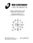
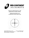
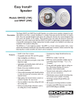
INSTALLATION MANUAL AND OPERATING INSTRUCTIONS M40-( ) Series COURSE DEVIATION INDICATOR CRS GPS (MD40-65L shown) Mid-Continent Instruments and Avionics 9400 E. 34th Street N., Wichita, KS 67226 USA Phone 316-630-0101 Fax 316-630-0723 (MD40-232L shown) Manual Number 2010085 REV B May 6, 2003 RECORD OF REVISIONS Revision N/R A B Revision Date 03-28-87 11-05-02 05-06-03 MD40-() CDI INSTALLATION MANUAL P/N 2010085 Rev. B Description Initial Release Changed Manual Format Added KLN 94B to pg. 11 Page 2 TABLE OF CONTENTS RECORD OF REVISIONS 1. 2 GENERAL DESCRIPTION 1.1 INTRODUCTION 1.2 EQUIPMENT DESCRITION 1.3 TECHNICAL SPECIFICATIONS 4 4 4 INSTALLATION 2.1 INTRODUCTION 2.2 EQUIPMENT LOCATION 2.3 COOLING AIR 2.4 ROUTING OF CABLES 2.5 EQUIPMENT LIMITATIONS 5 6 6 6 6 INSTALLATION PROCEDURES 3.1 GENERAL INFORMATION 3.2 UNPACKING AND INSPECTING EQUIPMENT 3.3 MOUNTING THE MD40 INDICATOR 3.4 INSTALLATION LIMITATIONS 6 7 7 7 POST INSTALLATION CHECKOUT 4.1 PRE-INSTALLATION TEST 4.2 OPERATING INSTRUCTIONS 4.3 AIRWORTHINESS STATEMENT 8 8 8 APPENDIX A: MD40-() APPLICATION CHART 11 APPENDIX B. ENVIRONMENTAL QUALIFICATION FORM, RTCA/DO-160B 12 2. 3. 4. LIST OF FIGURES FIGURE 3-1. CUTOUT DIMENSIONS FOR PANEL MOUNTING MD40-() WITH OUT RESOLVER FIGURE 3-2. CUTOUT DIMENSIONS FOR PANEL MOUNTING MD40-() WITH RESOLVER MD40-() CDI INSTALLATION MANUAL P/N 2010085 Rev. B 9 10 Page 3 1. 1.1 GENERAL DESCRIPTION INTRODUCTION This manual describes the physical, mechanical and electrical characteristics and the installation requirements for the MD40-() series Course Deviation Indicator (CDI). The appropriate CDI top level drawing must be used in conjunction with this installation manual for electrical interconnect. 1.2 EQUIPMENT DESCRIPTION The MD40 series Course Deviation Indicator is a compact, self-contained 2 1/4” indicator used to display output signals from various GPS and Loran receivers. The fully integrated display can provide annunciations, course error deviation, tofrom-off indication and OBS resolver output. Because of the wide selection of GPS and Loran systems, Mid-Continent offers over 60 versions of the MD40 indicator. In most cases, the selected unit will include all the necessary functions required for FAA approval of the installed GPS or Loran system. 1.3 TECHNICAL SPECIFICATIONS 1.3.1 Physical Characteristics (without resolver) Mounting Width Height Depth Behind Panel Weight Panel, 2 1/4 inch round instrument hole 2.39 inches 2.45 inches (2.53 lighted) 2.13 inches (2.27 lighted) 0.50 lbs max 1.3.2 Physical Characteristics (with resolver) Mounting Width Height Depth Behind Panel Weight MD40-() CDI INSTALLATION MANUAL P/N 2010085 Rev. B Panel, 2 1/4 inch round instrument hole 2.39 inches 2.45 inches (2.53 lighted) 4.72 inches (4.68 lighted) 1.0 lbs max Page 4 1.3.3 General Specifications Regulatory Compliance Applicable Documents Operating Temperature Range Humidity Altitude Range Operating Current Lighting Current Environmental Testing TSO C60a RTCA/DO-194 -55C to +70C 95% non-condensing 0 to 55,000 ft 20 mA max 90 mA max RTCA/DO-160B 1.3.3 Electrical Specifications OBS Resolver (when applicable) Deviation Input Impedance Deviation Deflection Sensitivity Super Flag input (when applicable) TO-OFF-FROM Flag Input Impedance TO-OFF-FROM Flag Sensitivity MD40-() CDI INSTALLATION MANUAL P/N 2010085 Rev. B Omni Range Zero: 300, calibrated at 30 Hz 1 K 15% 150 mV 15% for full scale deflection 11-33 Vdc 200 15% 40mV 15% for TO or FROM fully in view Page 5 2. INSTALLATION 2.1 INTRODUCTION Careful planning should be applied to achieve the desired performance and reliability form the MD40-() CDI. 2.2 EQUIPMENT LOCATION The MD40-() CDI must be mounted as close to the pilot’s field of view as possible. The unit depth, with connector attached, must also be taken into consideration. 2.3 COOLING AIR No direct cooling is required. As with any electronic equipment, overall reliability may be increased if the MD40-() CDI is not located near any high heat source or crowded next to other equipment. 2.4 ROUTING OF CABLES Care must be taken not to bundle the MD40-() CDI low level signal lines with any high energy sources. Examples of these sources include 400 HZ AC, Comm, DME, HF and transponder transmitter coax. Always use shielded wire when shown on the installation print. Avoid sharp bends in cabling and routing near aircraft control cables. 2.5 EQUIPMENT LIMATIONS The MD40 series Course Deviation Indicators are limited for use with Loran or GPS systems providing the required outputs necessary to match the listed input characteristics of the applicable MD40 indicator. For a fully TSO’d system the companion Loran or GPS system must also be certified to FAA TSO requirements. MD40-() CDI INSTALLATION MANUAL P/N 2010085 Rev. B Page 6 3. INSTALLATION PROCEDURES 3.1 GENERAL INFORMATION This section contains interconnect diagrams, mounting dimensions and other information pertaining to the installation of the MD40-() CDI. After installation of cabling and before installation of the equipment, ensure that power is applied only to the pins specified in the interconnect diagram. For wiring, you must have the correct top level drawing that matches the indicator you are currently installing. 3.2 UNPACKING AND INSPECTING When unpacking equipment, make a visual inspection for evidence of damage incurred during shipment. The following parts should be included: Item MD40-() CDI Installation Manual MD40-() Top level drawing 15 pin (sockets) connector kit 15 pin (pins) connector kit (required for MD40-2X2 indicators with resolver) 3.3 MCI Part Number 2010056-() 2010085 Rev A or later Drawing Number 2010056-() 8018293 8018285 QTY 1 1 1 1 A/R MOUNTING THE MD40-() INDICATOR Avoid mounting close to heater vents or other high heat sources. Allow a clearance of at least 3 inches from back of unit for plug removal. Make a panel cutout as shown in Figure 3.1 or 3.2. Secure the indicator in place with four 4-40 x 3/8 flat or round head screws with tinnerman nuts. 3.4 INSTALLATION LIMITATIONS Wire the aircraft harness according to the appropriate top level drawing. Use at least 24 AWG wire for all connections. You MUST use shielded wire where shown by the receiver manufacture. Avoid sharp bends and routing cable near high-energy sources. Care must be taken to tie the harness away from aircraft controls and cables. Also see equipment limitations, section 2.5. MD40-() CDI INSTALLATION MANUAL P/N 2010085 Rev. B Page 7 4 POST INSTALLATION CHECKOUT 4.1 PRE INSTALLATION TESTS With the MD40-() disconnected, turn on the avionics master switch and verify that aircraft power is on the appropriate pins. 4.2 OPERATING INSTRUCTIONS Operator should refer to the appropriate Loran or GPS Operating/Pilots Guide for explanations of various indications and annunciator functions. A complete ground test should be accomplished to determine proper annunciation and meter deflection. 4.3 AIRWORTHINESS STATEMENT No periodic scheduled maintenance or calibration is necessary for continued airworthiness of the MD40-(). If unit fails to perform to specifications, the unit must be removed and serviced by a qualified service facility. MD40-() CDI INSTALLATION MANUAL P/N 2010085 Rev. B Page 8 (MD40-65L shown) Figure 3.1 Cutout Dimensions for MD40-() series Indicator Without Resolver MD40-() CDI INSTALLATION MANUAL P/N 2010085 Rev. B Page 9 0 33 CRS 3 WPT OFF GPS GPS 15 18 21 CRS MSG (MD40-232 shown) Figure 3.1 Cutout Dimensions for MD40-() series Indicator With Resolver MD40-() CDI INSTALLATION MANUAL P/N 2010085 Rev. B Page 10 APPENDIX A: MD40-() APPLICATION CHART Manufacturer/Description Part Number Mid-Continent for Arnav STAR5000GPS STANDARD- VFR APR ALERT LIGHTED- VFR APR ALERT Mid-Continent for Northstar MD40-27 MD40-27L Mid-Continent for Freeflight TNL2000APR,2101(ALL) Manufacturer/Description Part Number 60 STANDARD- PTK WRN WPT LIGHTED- PTK WRN WPT M2, 6 STANDARD-ALERT WRN VFR PTK LIGHTED- ALERT WRN VFR PTK STANDARD-MSG WPT HLD APR LIGHTED-MSG WPT HLD APR MD40-66 MD40-66L STANDARD-ADV WRN APT WPT LIGHTED- ADV WRN APT WPT MD40-62 MD40-62L M3APR STANDARD- MSG HLD WPT APR LIGHTED-MSG HLD WPT APR MD40-68 MD40-68L M3IFR TNL2000T/2100T TNL8100, HT9000 Mid-Continent for Garmin GNC-250/XL STANDARD- MSG WPT LIGHTED- MSG WPT MD40-42 MD40-42L STANDARD- MSG LIGHTED- MSG MD40-22 MD40-22L STANDARD- MSG ARV LIGHTED- MSG ARV MD40-39 MD40-39L STANDARD- MSG WPT LIGHTED- MSG WPT MD40-242 MD40-242L GPS100AVD GPS150 GPS155(XL)/165(XL), GNC300(XL) Mid-Continent for Honeywell KLN-89A/90A STANDARD- MSG WPT LIGHTED- MSG WPT MD40-32 MD40-32L STANDARD- MSG WPT LIGHTED- MSG WPT MD40-232 MD40-232L STANDARD- MSG WPT LIGHTED- MSG WPT MD40-42 MD40-42L KLN-89B/90B/94B KLX-135/A MD40-43 MD40-43L M3 MD40-29 MD40-29L STANDARD- ALERT WRN VFR PTK RAIM LIGHTED- ALERT WRN VFR PTK RAIM MD40-41L STANDARD- APR PTK WPT MSG LIGHTED- APR PTK WPT MSG MD40-64 MD40-64L STANDARD- PTK WRN APR WPT LIGHTED- PTK WRN APR WPT MD40-61 MD40-61L Mid-Continent for Terra TGPS400D STANDARD- WRN ADV LIGHTED- WRN ADV MD40-38 MD40-38L Mid-Continent for UPS Aviation APOLLO 360, GX55, GX65 STANDARD- MSG PTK LIGHTED- MSG PTK GX50/60, 2001 GPS/TSO MD40-44 MD40-44L STANDARD- MSG PTK APR ACTV OBS HLD LIGHTED- MSG PTK APR ACTV OBS HLD SL50/60 STANDARD- MSG PTK OBS HLD LIGHTED- MSG PTK OBS HLD MD40-67 MD40-67L Mid-Continent for Various VARIOUS STANDARD- BASIC CDI LIGHTED- BASIC CDI MD40-09 MD40-09L Mid-Continent for Magellan SKYNAV 5000 STANDARD- NAV WPT GPS LIGHTED- NAV WPT GPS MD40-31 MD40-31L MD40-() CDI INSTALLATION MANUAL P/N 2010085 Rev. B Page 11 APPENDIX B: ENVIRONMENTAL QUALIFICATION FORM RTCA /DO160B NOMENCLATURE: MD40-() COURSE DEVIATION INDICATOR MODEL NO: MD40-() PART NUMBER: 2010056-() MANUFACTURER TEST SPECIFICATION: MPS 7015613 MANUFACTURER: Conditions Mid-Continent Instruments and Avionics 9400 E. 34th Street N. WICHITA, KS 67226 PHONE (316) 630-0101 Section Temperature and Altitude Low Temperature High Temperature Altitude Decompression Overpressure Temperature Variation Humidity Shock Operational Crash Safety Vibration 4.0 4.5.1 4.5.3 4.6.1 4.6.2 4.6.3 5.0 6.0 7.0 7.2 7.3 8.0 Explosion Waterproofness Fluids Susceptibility Sand and Dust Fungus Salt Spray Magnetic Effect 9.0 10.0 11.0 12.0 13.0 14.0 15.0 MD40-() CDI INSTALLATION MANUAL P/N 2010085 Rev. B Description of Conducted Tests Equipment tested to Categories B1 & F2 Category X: No test required Category X: No test required Equipment tested to Category B Equipment tested to Category A Equipment tested per DO-160B Par. 7.2.1 Category X: No test required Equipment tested without shock mounts to Categories P,K and S (Table 8-1) Category X: No test required Category X: No test required Category X: No test required Category X: No test required Category X: No test required Category X: No test required Equipment tested to Class Z Page 12