1
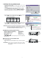
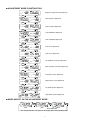
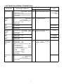
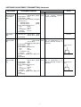
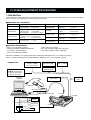
IC-2720H ADJUSTMENT PROCEDURES
1 PREPARATION
Some adjustments must be performed on the adjustment mode. OPC-478/U CLONING CABLE and CS-2720 CLONING SOFTWARE
(Rev.1.0 or later) are required when entering the adjustment mode.
‘ REQUIRED TEST EQUIPMENT
EQUIPMENT
DC power supply
RF power meter
(terminated type)
Frequency counter
FM deviation meter
GRADE AND RANGE
EQUIPMENT
Output voltage
Current capacity
: 13.8 V DC
: 20 A or more
Measuring range
Frequency range
Input impedance
: 1–100 W
: 100–600 MHz
: 50 kΩ/V DC or better
Frequency range
: 0.1–600MHz
Frequency accuracy : ±1 ppm or better
Sensitivity
: 100 mV or better
Frequency range
Measuring range
: 100–600 MHz
: 1–100 W
GRADE AND RANGE
Audio generator
Frequency range
output level
: 0.1–1000 MHz
: 1–500 mV
Attenuator
Power attenuation
Capacity
: 40–50 dB
: 100 W or more
Standard signal
generator (SSG)
Frequency range
output level
: 100–1200 MHz
: 0.1µV–32 mV
Oscilloscope
Frequency range
output level
: DC–20 MHz
: 0.01–20 V
AC millivoltmeter
Measuring range
: 10 mV–10 V
‘ SYSTEM REQUIREMENTS
• IBM® PC/AT compatible computer
• Microsoft® Windows® 98/98SE/2000/Me/XP
• At least 800 × 600 pixel display
• CS-2720 CLONING SOFTWARE
• USB or RS-232C serial port
• OPC-478 CLONING CABLE (RS-232C type)
OPC-478U CLONING CABLE (USB type)
Microsoft and Windows are registered trademarks of Microsoft Corporation in the U.S.A.and other countries.
IBM is a registered trademark of International Business Machines in the U.S.A. and other countries..
• CONNECTION
Standard signal generator
–127 to –17 dBm
(0.1 µV to 32 mV)
FM deviation meter
(DC measurable)
RF power meter
50 Ω / 1–100 W
Attenuator
40 dB or 50 dB
CAUTION:
DO NOT transmit while
the SSG is connected to
the antenna connector.
to the antenna connector
DC power supply
13.8V / 20 A
Personal
computer
to [DC 13.8V]
Frequency
counter
to USB port
OPC-478U (USB type)
to RS-232C port
Microphone connector
–
+
MIC GND
1
MIC INPUT
8
GND
OPC-478 (RS-232C type)
Audio
generator
AC
millivoltmeter
to [MIC]
PTT
1
to [SP2]
to [ANT]
2 ENTERING THE ADJUSTMENT MODE
q Install the CS-2720 CLONING SOFTWARE (Refer to the CS-2720
instruction manual in detail).
2 Right click the CS-2720’s icon on the desktop, then select the
“Property”.
3 Add “FX-2492AdjustStart” to the end of command line as follow.
"C\:Program Files\CS-2720\CS2720.exe" FX-2492AdjustStart
4 Connect the OPC-478/U CLONING CABLE to the speaker jack
[SP2], then double-click the CS-2720’s icon to run the program.
Add "FX-2492AdjustStart"to
the end of command line.
5 Click the [File] on the menu bar and select the [Open] to read the
icf file. (Select the file according to the version as follow.)
•ICF FILE EXPLANATION
ICF FILE VERSION ICF FILE VERSION
#02
EUR
#06
KOR
#03
ITR
#07
AUS
#04
TPE
#08
SEA
#05
USA
#09
EXP
Select the icf file.
6 Click the [Clone] on the menu bar and select the [Go Adjust Mode
F12] to enter the adjustment mode. “cLonE In” message is
appeared on the IC-2720H’s display while cloning.
CAUTION: Need to back up the original memory data to use CS-2720.
Otherwise, the transceiver’s memory channels are overwritten the data and deleted the original data at the same time
when cloning the adjustment frequency file (icf file).
Select to start the adjustment mode.
■ OPERATION ON THE ADJUSTMENT MODE
Change the adjustment channel [UP]
Change the adjustment channel [DOWN]
Change the adjustment value
Store the adjustment value
Select the mode
(FM AM FM-N FM)
Some adjustments need to push [SET] key
value to the CPU.
:
:
:
:
:
Right
Right
Right
Right
Right
[MAIN] key
[V/MHz] key
[DIAL]
[SET] key
[M/CALL] key
[SET]
[MAIN]
[V/MHz]
[M/CALL]
[DIAL]
to write the adjustment
‘ EXITING FROM THE ADJUSTMENT MODE
[PWR]
q Turn the power OFF.
w Push and hold the right and left [M/CALL] keys, and then turn power
ON.
ATTENTION: Need to cancel the adjustment mode when the adjustment is finished. Otherwise, the transceiver does not
work properly.
2
[M/CALL]
[M/CALL]
■
ADJUSTMENT MODE CONSTRUCTION
MAIN
T X
DUP
DTCS
AM
T SQL
MAIN
T X
DUP
T SQL
DTCS
AM
Frequency adjustment (Starting item)
BUSY LOWMID
BUSY LOWMID
M
M
SKIP
SKIP
MAIN
BAND
MAIN
T X
DUP
V/MHz
SCAN
DTCS
AM
T SQL
BUSY LOWMID
MAIN
T X
DUP
T SQL
BUSY LOWMID
M
VHF TX power adjustment
M
SKIP
SKIP
MAIN
BAND
MAIN
T X
DTCS
AM
V/MHz
SCAN
T SQL
DUP
DTCS
AM
MAIN
T X
DUP
T SQL
DTCS
AM
UHF TX power adjustment
BUSY LOWMID
BUSY LOWMID
M
M
SKIP
SKIP
MAIN
BAND
MAIN
T X
DUP
V/MHz
SCAN
T SQL
DTCS
AM
MAIN
T X
DUP
T SQL
DTCS
AM
VHF modulation adjustment
BUSY LOWMID
BUSY LOWMID
M
M
SKIP
SKIP
MAIN
BAND
MAIN
T X
DUP
V/MHz
SCAN
DTCS
AM
T SQL
MAIN
T X
DUP
T SQL
DTCS
AM
UHF modulation adjustment
BUSY LOWMID
BUSY LOWMID
M
M
SKIP
SKIP
MAIN
BAND
MAIN
T X
DUP
V/MHz
SCAN
DTCS
AM
T SQL
MAIN
T X
DUP
T SQL
DTCS
AM
VHF DTCS adjustment
BUSY LOWMID
BUSY LOWMID
M
M
SKIP
SKIP
MAIN
BAND
MAIN
T X
DUP
V/MHz
SCAN
DTCS
AM
T SQL
MAIN
T X
DUP
T SQL
DTCS
AM
UHF DTCS adjustment
BUSY LOWMID
BUSY LOWMID
M
M
SKIP
SKIP
MAIN
BAND
MAIN
T X
DUP
V/MHz
SCAN
DTCS
AM
T SQL
MAIN
T X
DUP
T SQL
DTCS
AM
Left band RX sensitivity adjustment
BUSY LOWMID
BUSY LOWMID
M
M
SKIP
SKIP
MAIN
BAND
MAIN
T X
DUP
V/MHz
SCAN
DTCS
AM
T SQL
BUSY LOWMID
MAIN
T X
DUP
T SQL
BUSY LOWMID
M
SKIP
DUP
Right band RX sensitivity adjustment
M
SKIP
MAIN
BAND
MAIN
T X
DTCS
AM
V/MHz
SCAN
DTCS
AM
T SQL
MAIN
T X
DUP
T SQL
DTCS
AM
Left band S-meter adjustment
BUSY LOWMID
BUSY LOWMID
M
M
SKIP
SKIP
MAIN
BAND
MAIN
T X
DUP
V/MHz
SCAN
T SQL
BUSY LOWMID
DTCS
AM
MAIN
T X
DUP
T SQL
BUSY LOWMID
M
SKIP
MAIN
BAND
DUP
Right band S-meter adjustment
M
SKIP
MAIN
T X
DTCS
AM
V/MHz
SCAN
DTCS
AM
T SQL
MAIN
T X
DUP
T SQL
DTCS
AM
Left band squelch adjustment
BUSY LOWMID
BUSY LOWMID
M
M
SKIP
SKIP
MAIN
BAND
MAIN
T X
DUP
V/MHz
SCAN
T SQL
BUSY LOWMID
DTCS
AM
MAIN
T X
DUP
T SQL
Right band squelch adjustment
BUSY LOWMID
M
M
SKIP
■
DTCS
AM
SKIP
MODE SELECT ON THE ADJUSTMENT MODE
MAIN
T X
DUP
T SQL
DTCS
AM
M/CALL
MW
BUSY LOWMID
M
MAIN
T X
DUP
M/CALL
MW
BUSY LOWMID
MAIN
T X
DUP
BUSY LOWMID
M
SKIP
SKIP
[FM]
DTCS
AM
T SQL
DTCS
AM
T SQL
M/CALL
MW
M
SKIP
[AM]
[FM-N]
*No decimal point
*The decimal point does not appear on the display while selected [FM-N] mode.
3
3 SOFTWARE ADJUSTMENT (TRANSMITTING)
ADJUSTMENT
MEASUREMENT
ADJUSTMENT CONDITION
UNIT
LOCATION
VALUE
REFERENCE
FREQUENCY
[Fr]
1 • Operating freq. : 450.000 MHz [USA] Rear Loosely couple a frequency
: 440.000 MHz [Other] panel counter to the antenna connec• Output power : Low
tor.
• Connect the RF power meter or 50 Ω
dummy load to the antenna connector.
• Transmitting
VHF OUTPUT
POWER
(HIGH)
[Po]
1 • Operating freq. : 145.000 MHz
[TPE], [KOR]
: 146.000 MHz
[USA], [ AUS], [SEA], [EXP]
• Output power : High
• Transmitting
(MID)
[Po]
2 • Output power : Mid
• Transmitting
22.0 W [TPE]
15.0 W [Other]
(LOW)
[Po]
3 • Output power : Low
• Transmitting
5.0 W
UHF OUTPUT
POWER
(HIGH)
[Po]
1 • Operating freq. : 450.000 MHz [USA]
: 440.000 MHz [Other]
• Output power : High
• Transmitting
(MID)
[Po]
2 • Output power : Mid
• Transmitting
HIGH FREQ.
[dE]
Rear Connect an RF power meter to
panel the antenna connector.
3
50.0 W
37.0 W
22.0 W [TPE]
15.0 W [Other]
• Output power : Low
• Transmitting
(LOW)
[Po]
VHF FM
MODULATION
LOW FREQ.
[dE]
Rear Connect an RF power meter to
panel the antenna connector.
450.0000 MHz
[USA]
440.0000 MHz
[Other]
5.0 W
•
•
1 •
•
Operating freq. : 144.000 MHz
Rear Connect an FM deviation meter
Output power : Low
panel to the antenna connector
IF bandwidth : Wide
through an attenuator.
Connect an audio generator to the [MIC]
jack and set as:
1.0 kHz/80 mVrms
[USA]
1.0 kHz/20 mVrms
[Other]
• Set an FM deviation meter as:
HPF
: 50 Hz
LPF
: 20 kHz
De-emphasis: OFF
Detector
: (P–P)/2
• Transmitting
±4.6 kHz
2 • Operating freq. :146.000 MHz
[TPE], [KOR]
: 148.000 MHz
[USA], [AUS], [SEA], [EXP]
• Transmitting
±4.6 kHz
4
SOFTWARE ADJUSTMENT (TRANSMITTING)-Continued
ADJUSTMENT
MEASUREMENT
ADJUSTMENT CONDITION
UNIT
LOCATION
VALUE
UHF FM
MODULATION
LOW FREQ.
[dE]
1 • Operating freq. : 440.000 MHz [USA] Rear Connect an FM deviation meter
: 430.000 MHz [Other] panel to the antenna connector
• Output power : Low
through an attenuator.
• IF bandwidth : Wide
• Connect an audio generator to the [MIC]
jack and set as:
1.0 kHz/80 mVrms
[USA]
1.0 kHz/20 mVrms
[Other]
• Set an FM deviation meter as:
HPF
: 50 Hz
LPF
: 20 kHz
De-emphasis: OFF
Detector
: (P–P)/2
• Transmitting
±4.6 kHz
HIGH FREQ.
[dE]
2 • Operating freq. : 450.000 MHz [USA]
: 440.000 MHz [Other]
• Transmitting
±4.6 kHz
VHF DTCS
WAVE FORM
[dt]
1 • Operating freq. : 145.100 MHz
Rear Connect an FM deviation meter
[TPE], [KOR] panel with an oscilloscope to the
: 146.100 MHz
antenna connector through an
[USA], [AUS], [SEA], [EXP]
attenuator.
• IF bandwidth : Wide
• Output power : Low
• Set an FM deviation meter as:
HPF
: OFF
LPF
: 20 kHz
De-emphasis: OFF
Detector
: (P–P)/2
• No signal is applied to the [MIC] connector.
• Transmitting
UHF DTCS
WAVE FORM
[dt]
1 • Operating freq. : 445.100 MHz [USA] Rear Connect an FM deviation meter
: 435.100 MHz [Other] panel with an oscilloscope to the
antenna connector through an
• IF bandwidth : Wide
attenuator.
• Output power : Low
• Set an FM deviation meter as:
HPF
: OFF
LPF
: 20 kHz
De-emphasis: OFF
Detector
: (P–P)/2
• No signal is applied to the [MIC] connector.
• Transmitting
5
Set to flat wave
form
Set to flat wave
form
SOFTWARE ADJUSTMENT (RECEIVING)
ADJUSTMENT
ADJUSTMENT CONDITION
OPERATION
Push the [SET] key.
SENSITIVITY 1 • Operating frequency : 118.200 MHz
• IF bandwidth
: Wide
LEFT BAND 1
• Connect the SSG to the antenna connector and set as :
[tr]
Level
: –97 dBm* (3.2 µV)
Modulation
: 1 kHz
Deviation
: ±3.5 kHz
• Receiving
2 • Operating frequency
• Receiving
: 146.200 MHz
Push the [SET] key.
3 • Operating frequency
• Receiving
: 179.800 MHz
Push the [SET] key.
SENSITIVITY 1 • Operating frequency
• Set the SSG level
LEFT BAND 2
• Receiving
[tr]
: 180.200 MHz
: –87 dBm* (10 µV)
Push the [SET] key.
2 • Operating frequency
• Set the SSG level
• Receiving
: 220.365 MHz
: –97 dBm* (3.2 µV)
Push the [SET] key.
3 • Operating frequency
• Receiving
: 259.800 MHz
Push the [SET] key.
: 260.200 MHz
: –97 dBm* (3.2 µV)
Push the [SET] key.
2 • Operating frequency
• Receiving
: 320.200 MHz
Push the [SET] key.
3 • Operating frequency
• Receiving
: 374.800 MHz
Push the [SET] key.
: 375.200 MHz
: –97 dBm* (3.2 µV)
Push the [SET] key.
SENSITIVITY 1 • Operating frequency
• Set the SSG level
LEFT BAND 3
• Receiving
[tr]
SENSITIVITY 1 • Operating frequency
• Set the SSG level
LEFT BAND 4
• Receiving
[tr]
2 • Operating frequency
: 430.200 MHz
: 410.200 MHz
[USA] Push the [SET] key.
[Other]
: 449.800 MHz
Push the [SET] key.
• Receiving
3 • Operating frequency
• Receiving
: 460.200 MHz
: 450.200 MHz
: –97 dBm* (3.2 µV)
[USA] Push the [SET] key.
[Other]
: 490.200 MHz
: 500.200 MHz
[USA] Push the [SET] key.
[Other]
: 549.800 MHz
Push the [SET] key.
: 118.200 MHz
: –97 dBm* (3.2 µV)
Push the [SET] key.
2 • Operating frequency
• Receiving
: 146.200 MHz
Push the [SET] key.
3 • Operating frequency
• Receiving
: 173.800 MHz
Push the [SET] key.
SENSITIVITY 1 • Operating frequency
LEFT BAND 5
• Set the SSG level
[tr]
• Receiving
2 • Operating frequency
• Receiving
3 • Operating frequency
• Receiving
SENSITIVITY 1 • Operating frequency
• Set the SSG level
RIGHT BAND 1
• Receiving
[tr]
*This output level of the standard signal generator (SSG) is indicated as SSG’s open circuit.
6
SOFTWARE ADJUSTMENT (RECEIVING)-Continued
ADJUSTMENT
ADJUSTMENT CONDITION
: 375.200 MHz
: –97 dBm* (3.2 µV)
Push the [SET] key.
2 • Operating frequency
• Receiving
: 410.200 MHz
Push the [SET] key.
3 • Operating frequency
• Receiving
: 449.800 MHz
Push the [SET] key.
: 450.200 MHz
: –97 dBm* (3.2 µV)
Push the [SET] key.
2 • Operating frequency
• Receiving
: 500.200 MHz
Push the [SET] key.
3 • Operating frequency
• Receiving
: 549.800 MHz
Push the [SET] key.
: 145.300 MHz
[TPE], [KOR]
: 146.300 MHz
[USA], [AUS], [SEA], [EXP]
• IF bandwidth
: Wide
• Connect the SSG to the antenna connector and set as :
Level
: –107 dBm* (1 µV)
Modulation
: 1 kHz
Deviation
: ±3.5 kHz
• Receiving
Push the [SET] key.
SENSITIVITY 1 • Operating frequency
• Set the SSG level
RIGHT BAND 2
• Receiving
[tr]
SENSITIVITY 1 • Operating frequency
• Set the SSG level
RIGHT BAND 3
• Receiving
[tr]
S-METER
LEFT BAND
[SL]
OPERATION
1 • Operating frequency
2 • Operating frequency
• Receiving
: 220.365 MHz
Push the [SET] key.
3 • Operating frequency
• Receiving
: 350.085 MHz
Push the [SET] key.
4 • Operating frequency
: 445.200 MHz
: 435.200 MHz
[USA]
[Other]
Push the [SET] key.
: 145.300 MHz
[TPE], [KOR]
: 146.300 MHz
[USA], [AUS], [SEA], [EXP]
Push the [SET] key.
: 445.200 MHz
: 435.200 MHz
Push the [SET] key.
• Receiving
1 • Operating frequency
S-METER
RIGHT BAND
[SL]
• Receiving
2 • Operating frequency
[USA]
[Other]
• Receiving
3 • Operating frequency
• Receiving
Push the [SET] key.
: 910.200 MHz
*This output level of the standard signal generator (SSG) is indicated as SSG’s open circuit.
7
SOFTWARE ADJUSTMENT (RECEIVING)-Continued
ADJUSTMENT
SQUELCH
LEFT BAND1
WIDE
[Sq]
ADJUSTMENT CONDITION
1 • Operating frequency
: 145.300 MHz
[TPE], [KOR]
: 146.300 MHz
[USA], [AUS], [SEA], [EXP]
• IF bandwidth
: Wide
• Connect the SSG to the antenna connector and set as :
Level
: –129 dBm* (0.079 µV)
Modulation
: 1 kHz
Deviation
: ±3.5 kHz
• Receiving
2 • Operating frequency
: 145.300 MHz
[TPE], [KOR]
: 146.300 MHz
[USA], [AUS], [SEA], [EXP]
OPERATION
Push the [SET] key.
Push the [SET] key 3 times.
• Receiving
SQUELCH
LEFT BAND 1
NARROW
[Sq]
(USA only)
SQUELCH
LEFT BAND 2
WIDE
[Sq]
SQUELCH
LEFT BAND 2
NARROW
[Sq] (USA)
1 • Operating frequency : 146.300 MHz
• IF band width
: Narrow
• Connect the SSG to the antenna connector and set as :
Level
: –129 dBm* (0.079 µV)
Modulation
: 1 kHz
Deviation
: ± 1.75 kHz
• Receiving
Set the FM-N mode and then push the
[SET] key.
2 • Operating frequency
• IF bandwidth
• Receiving
• Set the FM-N mode and then push the
[SET] key.
• Repeat the above operation 3 times.
: 146.300 MHz
: Narrow
1 • Operating frequency : 220.365 MHz
• IF band width
: Wide
• Connect the SSG to the antenna connector and set as :
Level
: –124 dBm* (0.14 µV)
Modulation
: 1 kHz
Deviation
: ±3.5 kHz
• Receiving
Push the [SET] key.
2 • Operating frequency
• Receiving
Push the [SET] key 3 times.
: 220.365 MHz
1 • Operating frequency : 220.365 MHz
• IF band width
: Narrow
• Connect the SSG to the antenna connector and set as :
Level
: –124 dBm* (0.14 µV)
Modulation
: 1 kHz
Deviation
: ± 1.75 kHz
• Receiving
Set the FM-N mode and then push the
[SET] key.
2 • Operating frequency
• IF bandwidth
• Receiving
• Set the FM-N mode and then push the
[SET] key.
• Repeat the above operation 3 times.
: 220.365 MHz
: Narrow
*This output level of the standard signal generator (SSG) is indicated as SSG’s open circuit.
8
SOFTWARE ADJUSTMENT (RECEIVING)-Continued
ADJUSTMENT
SQUELCH
LEFT BAND 3
WIDE
[Sq]
SQUELCH
LEFT BAND 3
NARROW
[Sq] (USA)
SQUELCH
LEFT BAND 4
WIDE
[Sq]
ADJUSTMENT CONDITION
OPERATION
1 • Operating frequency : 350.085 MHz
• IF band width
: Wide
• Connect the SSG to the antenna connector and set as :
Level
: –124 dBm* (0.14 µV)
Modulation
: 1 kHz
Deviation
: ±3.5 kHz
• Receiving
Push the [SET] key.
2 • Operating frequency
• Receiving
Push the [SET] key 3 times.
: 350.085 MHz
1 • Operating frequency : 350.085 MHz
• IF bandwidth
: Narrow
• Connect the SSG to the antenna connector and set as :
Level
: –124 dBm* (0.14 µV)
Modulation
: 1 kHz
Deviation
: ± 1.75 kHz
• Receiving
Set the FM-N mode and then push the
[SET] key.
2 • Operating frequency
• IF bandwidth
• Receiving
• Set the FM-N mode and then push the
[SET] key.
• Repeat the above operation 3 times.
: 350.085 MHz
: Narrow
1 • Operating frequency
: 445.200 MHz
[USA]
: 435.200 MHz
[Other]
• IF band width
: Wide
• Connect the SSG to the antenna connector and set as :
Level
: –129 dBm* (0.079 µV)
Modulation
: 1 kHz
Deviation
: ±3.5 kHz
• Receiving
2 • Operating frequency
: 445.200 MHz
: 435.200 MHz
[USA]
[Other]
Push the [SET] key.
Push the [SET] key 3 times.
• Receiving
SQUELCH
LEFT BAND 4
NARROW
[Sq] (USA)
1 • Operating frequency : 445.200 MHz
• IF bandwidth
: Narrow
• Connect the SSG to the antenna connector and set as :
Level
: –129 dBm* (0.079 µV)
Modulation
: 1 kHz
Deviation
: ± 1.75 kHz
• Receiving
Set the FM-N mode and then push the
[SET] key.
2 • Operating frequency
• IF bandwidth
• Receiving
• Set the FM-N mode and then push the
[SET] key.
• Repeat the above operation 3 times.
: 445.200 MHz
: Narrow
This output level of the standard signal generator (SSG) is indicated as SSG’s open circuit.
9
SOFTWARE ADJUSTMENT (RECEIVING)-Continued
ADJUSTMENT
ADJUSTMENT CONDITION
OPERATION
1 • Operating frequency : 145.300 MHz
[TPE], [KOR] Push the [SET] key.
SQUELCH
: 146.300 MHz
RIGHT BAND 1
[USA], [AUS], [SEA], [EXP]
WIDE
• IF band width
: Wide
[Sq]
• Connect the SSG to the antenna connector and set as :
Level
: –129 dBm* (0.079 µV)
Modulation
: 1 kHz
Deviation
: ±3.5 kHz
• Receiving
2 • Operating frequency
: 145.300 MHz
[TPE], [KOR] Push the [SET] key 3 times.
: 146.300 MHz
[USA], [AUS], [SEA], [EXP]
• Receiving
1 • Operating frequency : 445.200 MHz
[USA] Push the [SET] key.
SQUELCH
: 435.200 MHz
[Other]
RIGHT BAND 2
• IF band width
: Wide
WIDE
• Connect the SSG to the antenna connector and set as :
[Sq]
Level
: –129 dBm* (0.079 µV)
• Receiving
2 • Operating frequency
[USA] Push the [SET] key 3 times
[Other]
: 445.200 MHz
: 435.200 MHz
• Receiving
Push the [SET] key.
1 • Operating frequency : 910.200 MHz
SQUELCH
• IF band width
: Wide
RIGHT BAND 3
• Connect the SSG to the antenna connector and set as :
WIDE
Level
: –110 dBm* (0.71 µV)
[USA]
[Sq]
: –119 dBm* (0.25 µV)
[Other]
• Receiving
2 • Operating frequency
• Receiving
Push the [SET] key 3 times.
: 910.200 MHz
This output level of the standard signal generator (SSG) is indicated as SSG’s open circuit.
10
4 ADJUSTMENT MODE CONTENTS LIST
Some adjustment frequency depend on the version.
Left band (VHF)
NO.
Frequency display
Right band (UHF)
Mch
Frequency display
Mch
Change inhibited
Fr
Frequency adjustment
Change permitted
––––8F
––
VHF TX power adjustment
Change permitted
4 4 0.0 0 0
Po
VHF TX power adjustment
Change permitted
––––62
––
MAIN
4 4 0.0 0 0
Fr
1
––––Ad
––
MAIN
4 4 0.0 0 0
Fr
2
––––dA
––
MAIN
4 4 0.0 0 0
Fr
3
––––8A
––
MAIN
4 4 0.0 0 0
Fr
4
––––76
––
MAIN
4 4 0.0 0 0
Fr
5
––––80
––
MAIN
4 4 0.0 0 0
Fr
6
––––8c
––
MAIN
4 4 0.0 0 0
Fr
7
––––78
––
MAIN
4 4 0.0 0 0
Fr
8
––––Fc
––
MAIN
4 4 0.0 0 0
1 4 5.0 0 0
Po
––––65
––
MAIN
10
MAIN
Presetting value
Initial data
0
9
Adjustment contents
11
MAIN
1 4 4.0 0 0
dE
––––A0
––
Modulation adjustment for
lowest frq.(VHF)
Change permitted
12
MAIN
1 4 6.0 0 0
dE
––––9d
––
Modulation adjustment for
highest frq.(VHF)
Change permitted
13
––––8D
––
4 3 0.0 0 0
dE
Modulation adjustment for
lowest frq.(UHF)
Change permitted
14
––––85
––
4 4 0.0 0 0
dE
Modulation adjustment for
highest frq.(UHF)
Change permitted
15
MAIN
1 4 5.1 0 0
dt
––––FF
––
DTCS adjustment
Change inhibited
16
MAIN
1 4 5.1 0 0
dt
––––88
––
DTCS adjustment
Change permitted
17
––––00
––
MAIN
4 3 5.1 0 0
dt
DTCS adjustment
Change permitted
18
––––67
––
MAIN
4 3 5.1 0 0
dt
DTCS adjustment
Change inhibited
Change permitted
19
MAIN
1 1 8.2 0 0
tr
2F2431
52
To set t1 tracking
20
MAIN
1 4 6.2 0 0
tr
83718E
5b
To set t2 tracking
21
MAIN
1 7 9.8 0 0
tr
bbAFEA
Ad
To set t3 tracking
22
MAIN
1 8 0.2 0 0
tr
26287F
4c
To set t1 tracking
23
MAIN
2 2 0.3 6 5
tr
7E6380
80
To set t2 tracking
24
MAIN
2 5 9.8 0 0
tr
Ec9b7F
80
To set t3 tracking
25
MAIN
2 6 0.2 0 0
tr
4A4380
80
To set t1 tracking
26
MAIN
3 2 0.2 0 0
tr
898655
27
To set t2 tracking
27
MAIN
3 7 4.8 0 0
tr
9ccA80
7d
To set t3 tracking
28
MAIN
3 7 5.2 0 0
tr
3d1E4A
25
To set t1 tracking
29
MAIN
4 1 0.2 0 0
tr
917F86
8b
To set t2 tracking
30
MAIN
4 4 9.8 0 0
tr
ddd8Eb
Ec
To set t3 tracking
31
MAIN
4 5 0.2 0 0
tr
624644
8F
To set t1 tracking
32
MAIN
5 0 0.2 0 0
tr
c08F88
EF
To set t2 tracking
33
MAIN
5 4 9.8 0 0
tr
EEd9cc
Eb
To set t3 tracking
34
363030
43
MAIN
1 1 8.2 0 0
tr
To set t1 tracking
35
7d807E
64
MAIN
1 4 6.2 0 0
tr
To set t2 tracking
36
A8AcF1
9b
MAIN
1 7 3.8 0 0
tr
To set t3 tracking
11
Change permitted
Change permitted
Change permitted
Change permitted
Change permitted
ADJUSTMENT MODE CONTENTS LIST (Continued)
Some adjustment frequency depend on the version.
Left band (VHF)
NO.
Frequency display
Right band (UHF)
Mch
Frequency display
Adjustment contents
Presetting value
Mch
37
3c4A62
0E
MAIN
3 7 5.2 0 0
tr
To set t1 tracking
38
9cA29E
79
MAIN
4 1 0.2 0 0
tr
To set t2 tracking
39
b8EdFb
Ac
MAIN
4 4 9.8 0 0
tr
To set t3 tracking
40
20636A
6c
MAIN
4 5 0.2 0 0
tr
To set t1 tracking
41
AEb3A7
AE
MAIN
5 0 0.2 0 0
tr
To set t2 tracking
42
d9f1F5
F7
MAIN
5 4 9.8 0 0
tr
To set t3 tracking
Change permitted
Change permitted
43
MAIN
1 4 5.3 0 0
SL
––––FF
––
S-meter adjustment
Change permitted
44
MAIN
2 2 0.3 6 5
SL
––––F3
––
S-meter adjustment
Change permitted
45
MAIN
3 5 0.0 8 5
SL
––––F5
––
S-meter adjustment
Change permitted
46
MAIN
4 3 5.2 0 0
SL
––––FA
––
S-meter adjustment
Change permitted
47
––––F2
––
MAIN
1 4 5.3 0 0
SL
S-meter adjustment
Change permitted
48
––––F2
––
MAIN
4 3 5.2 0 0
SL
S-meter adjustment
Change permitted
49
––––EE
––
MAIN
9 1 0.2 0 0
SL
S-meter adjustment
Change permitted
Change permitted
50
MAIN
1 4 5.3 0 0
Sq
00FF04
––
SQL level adjustment
(Open tight) N/W
51
MAIN
1 4 5.3 0 0
Sq
00FF30
––
SQL level adjustment
(Open threshold) N/W
52
MAIN
1 4 5.3 0 0
Sq
00FF24
––
SQL level adjustment
(Close tight) N/W
53
MAIN
1 4 5.3 0 0
Sq
00FF36
––
SQL level adjustment
(Close threshold) N/W
54
MAIN
2 2 0.3 6 5
Sq
00FF04
––
SQL level adjustment
(Open tight) N/W
55
MAIN
2 2 0.3 6 5
Sq
00FF31
––
SQL level adjustment
(Open threshold) N/W
56
MAIN
2 2 0.3 6 5
Sq
00FF24
––
SQL level adjustment
(Close tight) N/W
57
MAIN
2 2 0.3 6 5
Sq
00FF3A
––
SQL level adjustment
(Close threshold) N/W
58
MAIN
3 5 0.0 8 5
Sq
00FF04
––
SQL level adjustment
(Open tight) N/W
59
MAIN
3 5 0.0 8 5
Sq
00FF2E
––
SQL level adjustment
(Open threshold) N/W
60
MAIN
3 5 0.0 8 5
Sq
00FF22
––
SQL level adjustment
(Close tight) N/W
61
MAIN
3 5 0.0 8 5
Sq
00FF3b
––
SQL level adjustment
(Close threshold) N/W
62
MAIN
4 3 5.2 0 0
Sq
00FF04
––
SQL level adjustment
(Open tight) N/W
63
MAIN
4 3 5.2 0 0
Sq
00FF2E
––
SQL level adjustment
(Open threshold) N/W
64
MAIN
4 3 5.2 0 0
Sq
00FF22
––
SQL level adjustment
(Close tight) N/W
65
MAIN
4 3 5.2 0 0
Sq
00FF3A
––
SQL level adjustment
(Close threshold) N/W
N/W: Narrow/Wide
12
Change permitted
Change permitted
Change permitted
ADJUSTMENT MODE CONTENTS LIST (Continued)
Some adjustment frequency depend on the version.
Left band (VHF)
NO.
Frequency display
Right band (UHF)
Mch
Frequency display
Adjustment contents
66
00FF04
––
MAIN
1 4 5.3 0 0
Sq
SQL level adjustment
(Open tight) N/W
67
00FF24
––
MAIN
1 4 5.3 0 0
Sq
SQL level adjustment
(Open threshold) N/W
68
00FF1d
––
MAIN
1 4 5.3 0 0
Sq
SQL level adjustment
(Close tight) N/W
69
00FF34
––
MAIN
1 4 5.3 0 0
Sq
SQL level adjustment
(Close threshold) N/W
70
00FF04
––
MAIN
4 3 5.2 0 0
Sq
SQL level adjustment
(Open tight) N/W
71
00FF29
––
MAIN
4 3 5.2 0 0
Sq
SQL level adjustment
(Open threshold) N/W
72
00FF1E
––
MAIN
4 3 5.2 0 0
Sq
SQL level adjustment
(Close tight) N/W
73
00FF34
––
MAIN
4 3 5.2 0 0
Sq
SQL level adjustment
(Close threshold) N/W
74
00FF04
––
MAIN
9 1 0.2 0 0
Sq
SQL level adjustment
(Open tight) N/W
75
00FF2c
––
MAIN
9 1 0.2 0 0
Sq
SQL level adjustment
(Open threshold) N/W
76
00FF21
––
MAIN
9 1 0.2 0 0
Sq
SQL level adjustment
(Close tight) N/W
77
00FF31
––
MAIN
9 1 0.2 0 0
Sq
SQL level adjustment
(Close threshold) N/W
78
MAIN
1 4 5.1 0 0
ct
––––FF
––
CTCSS auto generation
79
MAIN
1 4 5.1 0 0
dt
––––d6
––
DTCS auto generation
80
––––FF
––
MAIN
4 3 5.1 0 0
ct
CTCSS auto generation
81
––––d6
––
MAIN
4 3 5.1 0 0
dt
DTCS auto generation
1 4 5.0 0 0
re
––––9E
––
TX protection voltage
––––8d
––
4 4 0.0 0 0
re
TX protection voltage
1 4 5.0 0 0
––
––––00
––
––––00
––
4 4 0.0 0 0
––
From 84 to 199 normal
operation
82
MAIN
83
84
MAIN
85
MAIN
MAIN
199
N/W: Narrow/Wide
13
Presetting value
Mch
Change permitted
Change permitted
Change permitted
Change inhibited
Change inhibited