1
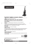
INS T AL L AT ION AND S ERVICE MANU AL MANU AL DE L A INST AL ACIÓN Y S ER VICIO Un Con der ce i l in g so l e 1 INDEX www.totaline.com.ar 2 MATERIAL DE CONSULTA Este material pertenece al website de TOTALINE ARGENTINA PROHIBIDA SU REPRODUCCIÓN O MODIFICACIÓN 1. INTRODUCTION ................................................................................................... 03 2. NOMENCLATURE ................................................................................................ 03 3. SAFETY INSTRUCTIONS ..................................................................................... 04 4. UNIT RECEPTION AND INSPECTION ................................................................. 04 5. INSTALLATION ..................................................................................................... 04 5.1. GENERAL RECOMMENDATIONS ........................................................... 04 5.2. BASIC INSTALLATION PROCEDURE ..................................................... 05 5.3. EVAPORATING UNIT INSTALLATION ..................................................... 06 5.3.1. General recommendations .......................................................... 06 5.3.2. Positioning ................................................................................... 06 5.3.3. Condensate drain ........................................................................ 08 6. INTERCONNECTION PIPINGS ............................................................................ 09 6.1. INTERCONNECTION PIPING HANGING AND ATTACHMENT. .............. 09 6.2. INTERCONNECTION PIPING EVACUATION .......................................... 09 7. ELECTRIC INTERCONNECTIONS ...................................................................... 10 7.1. USA A COMMAND 220 V ELECTRIC CHART ......................................... 10 7.2. USA A COMMAND 24 V ELECTRIC CHART ........................................... 11 8. FIRST START-UP ................................................................................................. 12 9. COOLING SYSTEM ............................................................................................. 12 9.1. EXPANSION SYSTEM ............................................................................. 12 10.MAINTENANCE ................................................................................................... 13 10.1. GENERAL TOPICS ................................................................................. 13 10.2. PREVENTIVE MAINTENANCE .............................................................. 13 10.3. CORRECTIVE MAINTENANCE ............................................................. 13 10.4. LEAK DETECTION ................................................................................. 13 10.4.1. Detection Methods .................................................................... 13 10.4.2. Leak Repair ............................................................................... 14 10.5. VACUUM AND REFRIGERANT CHARGE PROCEDURE ..................... 14 10.5.1. Dehydration ............................................................................... 14 10.5.2. Refrigerant Charge .................................................................... 14 10.6. SYSTEM INTERNAL CLEANING ........................................................... 15 10.7. REFRIGERANT COLLECTING .............................................................. 15 10.8. GENERAL CARE .................................................................................... 15 11. TROUBLESHOOTING GUIDE ............................................................................ 16 12. PREVENTIVE MAINTENANCE CHART ............................................................. 18 13. GENERAL TECHNICAL FEATURES ................................................................. 19 14. GENERAL INSTALLATION TIPS ...................................................................... 19 1. INTRODUCTION This manual is addressed to properly trained installers with the purpose of helping in installation and maintenance procedures. It is important to stress that any repairs or services can be dangerous if accomplished by not properly trained personnel. Only properly trained staff should install, start up and give any maintenance to the equipment mentioned on this manual. If after the reading, you still need additional information just get in contact with us! US A A 12 C 5 O PROHIBIDA SU REPRODUCCIÓN O MODIFICACIÓN 2. NOMENCLATURE MATERIAL DE CONSULTA _ - WIRED REMOTE CONTROL 24 V O - WIRED REMOTE CONTROL - 220V D - WIRELESS REMOTE CONTROL - 24V EVAPORATING UNIT M - WIRED REMOTE CONTROL & SWEEP MOTOR - 24V AMBIENT N - WIRELESS REMOTE CONTROL WITHOUT SWEEP MOTOR - 24V IDENTIFICATION IN THE PROJECT CHANGES (VERSION) 12 24 36 48 = = = = 12.000 24.000 36.000 48.000 BTU/h BTU/h BTU/h BTU/h 18 30 42 60 = = = = 18.000 30.000 42.000 60.000 NOMINAL FREQUENCY 5 - 50 Hz 6 - 60 Hz BTU/h BTU/h BTU/h BTU/h C - COOLING H - COOLING AND HEATING LIST OF SYMBOLS - Ground - Caution - Risk of electric discharge - Fuse - Read the manual before using V - Volt A - Amps Hz - Hertz W - Watt Kg - Kilogram Oz - Ounce in - in IPXX - IP number Este material pertenece al website de TOTALINE ARGENTINA www.totaline.com.ar 3 3. SAFETY INSTRUCTIONS The new indoor units US A were projected to offer you a safe and reliable service when operated within the specifications foreseen in project. However, due to this same conception, aspects regarding installation, start up and maintenance should be strictly observed. WARNING FIGURE 1 - HANDLING OF US A UNITS. * Observe the limit of suitable piling up indicated in the units’ packing. * Don’t shake the outdoor unit during transportation nor incline more than 15o in the vertical. * Avoid exposing the machine labor accidents, seeing to it that it is immediately carried to the installation site or a safe place. * When removing the units from the package and removing the expanded polystyrene protections don’t discard them immediately because they may be useful eventually as protection against dust, or other noxious agents until the building and/or installation is complete and system ready to operate. WARNING * Verify the weights and dimensions of the units (see item 13) to guarantee an appropriate and safe handling. * Learn how to handle the oxyacetylene equipment safely. Leave the equipment in the vertical position inside the vehicle and also in the working place. * Use dry nitrogen to pressurize and to check the system for leaks. Use a good regulator. Be careful not to exceed 200 psig of test pressure in the rotary compressors. * Before working in any one of the units always turn off the power supply unplugging the indoor unit from the wall outlet. * Never introduce the hands or any other object inside the units while the fan is working. 5. INSTALLATION 5.1 GENERAL RECOMMENDATIONS First, consult the norms or codes applicable to the installation of the equipment in the selected place, to make sure the system is in accordance to them. Make also a careful planning of the unit location to avoid interference with any type of existing (or planned) 4. RECEPTION AND INSPECTION facilities, such as electrical installation, water piping, sewer, OF THE UNITS etc. Install the units so that they are free from any type of * To avoid damages during handling or transport, don’t obstruction from the taking of return air or airflow. remove the unit’s packing until arrive to the defined Choose places with enough clearance for repairs or place of installation. services of any kind and also to make the piping * Prevent strings, chains or other devices from touching easier(copper tubes that interconnect the units, electrical the units. wiring and drain). Remember that the units should be leveled after their WARNING installation. Este material pertenece al website de TOTALINE ARGENTINA Verify if the external place is free of dust or other * Never lift or carry the evaporator unit by the particles that might obstruct the condenser coil. www.totaline.com.ar plastic side parts. Hold it on the metal parts, as shown on figure 1. 4 MATERIAL DE CONSULTA PROHIBIDA SU REPRODUCCIÓN O MODIFICACIÓN * Always maintain the fire extinguisher close to the working place. Check the extinguisher periodically to certify it is completely loaded and working perfectly. * When working in the equipment always observe the safety warnings in the labels attached to the units. * Always follow all the applicable norms of safety and use clothes and equipment of personal protection. Wear gloves and protection glasses when handling the units or the system refrigerant. It is indispensable that the indoor unit possesses hydraulic line for drainage of the condenser. This hydraulic line should not have a diameter less then 1/2" and should have, right after the exit, a siphon to guarantee a perfect fall and isolation of air. At the start up, this siphon should be filled in with water to avoid taking air from the drainage line. The drainage in the outdoor unit is indispensable only when installed in the high and causing leak risk. 5.2 BASIC PROCEDURES FOR INSTALLATION * INDOOR UNIT US A CHOICE OF POSITION FOR INSTALLATION HOLE IN THE WALL (Ø10cm) POSITION OF INTERCONNECTION PIPING ò INSTALLATION OF HYDRAULIC PIPING FOR THE DRAIN ò ASSEMBLY *OUTDOOR UNIT ò CHOICE OF LOCATION INSTALLATION OF HYDRAULIC ò PIPING FOR THE DRAIN ASSEMBLY *INTERCONNECTION CONNECTION TO ò Este material pertenece al website de TOTALINE ARGENTINA ò www.totaline.com.ar INTERCONNECTION PIPING ELECTRICAL CONNECTIONS FINAL DETAILS 5 MATERIAL DE CONSULTA PROHIBIDA SU REPRODUCCIÓN O MODIFICACIÓN ò ò ò CHOICE OF LOCATION 5.3 EVAPORATING UNIT INSTALLATION 5.3.1 - GENERAL RECOMMENDATIONS WRONG Before installing, read this instructions carefully to get familiar with the unit’s features. Sizes and weights can be found on item 14 on this manual. The following rules apply to all installations. CORRECT a) Plan the units’ placement carefully to avoid occasional interference with any existing (or planned) installations, such as electrical installation, water piping, drain, etc. WRONG b) Install the unit so that it is free from any type of obstruction on the air flow, both on the air outflow and air intake. FIGURE 2 - EVAPORATING UNIT POSITION IN ROOM d) The place should allow for the passage of piping (system pipes, electric wires and drain). e) The unit should be leveled after installation. 5.3.2 - POSITIONING a) The unit should only be installed horizontally Underceiling, vertically on the floor (console mode) or on the wall (see fig. 4 and 5) b) The unit comes with two (2) brackets for Underceiling or on the wall installation. There is also a brace for assembly of the remote control. c) Figure 6 indicates the positioning of the screws on the brackets. d) Install the brackets (figure 3) underceiling by using the screws, nuts and washers. e) The unit should be positioned so as to distribute the air flow uniformly in the room. Capacity (BTU/h) A B C 12 and 18.000 1000 822 792 24 and 30.000 1380 1202 1172 www.totaline.com.ar 48 and 60.000 2140 1962 1932 Este material pertenece al website de TOTALINE ARGENTINA 1582 1552 36 and 42.000 1760 FIGURE 3 - SIZES FOR EVAPORATING UNIT INSTALLATION 6 MATERIAL DE CONSULTA PROHIBIDA SU REPRODUCCIÓN O MODIFICACIÓN c) Choose an installation place with enough clearance for maintenance and general repair. 300 mm 300 mm MINIMUM MINIMUM SEE DETAIL A DETAIL A SCALE 1:4 Este material pertenece al website de TOTALINE ARGENTINA www.totaline.com.ar FIGURE 6 - BRACKET ASSEMBLY 7 MATERIAL DE CONSULTA FIGURE 5 - CONSOLE ASSEMBLY (ON THE FLOOR) PROHIBIDA SU REPRODUCCIÓN O MODIFICACIÓN FIGURE 4 - UNDERCEILING INSTALLATION 5.3.3 - CONDENSATE DRAIN According to the type of installation (console or under ceiling), there are two positions on the side plastic parts where the drain and interconnection pipes must pass through. The following picture shows where the cover must be broken. CONSOLE MODE When connecting the PVC hose to the machine, do not do it with sudden movements or too much force, as this may cause leaks. If necessary, heat the PVC before connecting it or use a flexible hose. FIGURE 7 - POSITION WHERE COVERS MUST BE BROKEN a) Make sure that the unit is leveled, with a slight slant towards the drain so as to assure a proper draining. b) Connect the 1/2” PVC piping to the drain connection (Figure 8). c) The unit uses drain by gravity. The drain pipes should have declivity, though. Avoid scenarios like the ones indicated on Figure 9. Este material pertenece al website de TOTALINE ARGENTINA www.totaline.com.ar FIGURE 8 8 MATERIAL DE CONSULTA WARNING UNDERCEILING MODE PROHIBIDA SU REPRODUCCIÓN O MODIFICACIÓN FIGURE 9 - INEFFECTIVE DRAINING SCENARIO 6. INTERCONNECTION PIPING 6.1. SUSPENSION AND FIXATION OF INTERCONNECTION PIPES Always try to fasten the interconnection piping in a convenient way through brackets or porches, preferably both together. Seal them with circular neoprene bushing and then pass finish ribbon around. Test all the welded and flared connections looking for leaks (maximum tested pressure: 200 psig). Use pressure regulator in the Nitrogen cylinder. If necessary, pass the electric interconnection by the copper tube, as shown on Figure 10. ELECTRICAL INTERCONNECTION DUCT (OPTIONAL) LIQUID LINE SUCTION LINE TAPE ISOLATION TUBES TAPE FIGURE 10 - INTERCONNECTION PIPES MATERIAL DE CONSULTA The outdoor unit is shipped with enough refrigerant charge for use in a system with interconnection piping up to 3m, that is, charge for the outdoor unit, charge for the indoor unit and the necessary charge for an interconnection piping up to 3m. Since the interconnection pipes are provided in the field, you should proceed with the evacuation of the lines and of the indoor unit. The access points are the service valves close to the outdoor unit. The valves come shut from the plant to retain the refrigerant in the outdoor unit. To do the evacuation, maintain the valve shut and connect one side of the manifold hose to the vent’s valve and the other to the vacuum pump. It is recommended to proceed the evacuation through both connections of the service valves simultaneously. The range to be reached should stay between 250 and 500 microns. OBS: After doing the evacuation, add positive pressure with R-22 so that the vacuum is broken (see figure 4). PROHIBIDA SU REPRODUCCIÓN O MODIFICACIÓN ISOLATION 6.2. EVACUATION OF INTERCONNECTION PIPING To proceed with the refrigerant charge, just maintain the service valve in the original position (shut) and connect the manifold hose to the vent (valve Schrader) of the service valve. OBS: Do not forget to purge the air from the hose. WARNING For all the necessary information about diameter, charge and connections, see topics 13 and 14. Before turning on the equipment and after completing the refrigerant charge (if necessary), open the service valves close to the outdoor unit. CAUTION Never carry liquid in the suction service valve. Whenever you want to do it, use the service valve of the liquid line. Este material pertenece al website de TOTALINE ARGENTINA www.totaline.com.ar 9 1 - MOTOR USED ONLY IN 36, 42, 48, 60K MACHINES 2 - USED ONLY IN HEAT PUMP MACHINES 3 - MOTOR USED ONLY IN SWEEP MOTOR DRIVED MACHINES 7 - ELECTRIC INTERCONNECTIONS CAPTION - - - - LOCALLY MADE WIRING FACTORY MADE WIRING RV - REVERSION VALVE 7.1 - US A COMMAND 220 V ELECTRIC CHART On condensors that operate on cooling with the reversion valve energized, the electric interconnection must be made between P9 and P10 of the Printed Circuit Board and the reversion valve. MATERIAL DE CONSULTA PROHIBIDA SU REPRODUCCIÓN O MODIFICACIÓN 10 CAUTION CAPTION - - - - LOCALLY MADE WIRING FACTORY MADE WIRING TFX - 220/24 V TRANSFORMER RV - REVERSION VALVE 1 - MOTOR USED ONLY IN 36, 42, 48, 60K MACHINES 2 - USED ONLY IN QL AND QW MACHINES 3 - MOTOR USED ONLY IN QL, CWS, CL MACHINES 4 - WHEN USING 38NX/NW/RC/RQ CONDENSERS IT IS NECESSARY TO DISCONNECT THE ORANGE CABLE(S) FROM THE TRANSFORMER AND CONNECT IT (THEM) TO TERMINAL 2 ON THE TERMINAL BLOCK 7.2 - US A COMMAND 24 V ELECTRIC CHART On condensors that operate on cooling with the reversion valve energized, the electric interconnection must be made between P9 and P10 of the Printed Circuit Board and the reversion valve. MATERIAL DE CONSULTA PROHIBIDA SU REPRODUCCIÓN O MODIFICACIÓN 11 CAUTION 8. INITIAL START - UP 9. COOLING SYSTEM 9 .1 - EXPANSION SYSTEM Before turn the unit on, check the conditions above and the following items: The evaporator units are factory-equipped with a system for refrigerant gas expansion called piston. * Verify the appropriate fixation of all the electrical connections; As shown below, this system has a small piece with a fixed, calibrated, easily removable hole inside a nipple to connect a 3/8” flare nut on the liquid line. * Make sure there is no refrigerant leakage; The piston application properties include a more accurate refrigerant gas flow into the evaporator compared, for instance, with the capillary system. Besides, pistons are easy to handle. * Make sure the power supply is compatible with the electrical characteristics of the unit; * Make sure the compressors can move freely on the vibration insulators of the outdoor unit; * Make sure that all the service valves are in the correct operation position; EXPANSION DIRECTION * Make sure to have a perfect drainage and no blockage in the drain’s hose of the unit; * When the outdoor temperature is too low, there will be a risk of freezing the indoor unit if the operation speed was adjusted to the minimum condition (cooling mode). CAUTION The fan motors of the units are lubricated in the plant. Dont lubricate when installing the units. Before turning on the motor, make sure the propeller or turbine fan is not loose. BY - PASS DIRECTION Este material pertenece al website de TOTALINE ARGENTINA www.totaline.com.ar 12 MATERIAL DE CONSULTA * Make sure the area around the outdoor unit is free of any obstruction in the taking or discharge of the airflow; PROHIBIDA SU REPRODUCCIÓN O MODIFICACIÓN On reverse cycles (heating and cooling), the piston system requires a by-pass system, that is, two pieces are placed inside the nipple, one performing the expansion process and the other as a by-pass and vice-versa according to the gas flow direction (cooling or heating mode). 10. MAINTENANCE CONTROLS - Make sure that all the controls are working correctly and that the units operation is normal. Vibrations can cause undesirable noises. DRAIN - Verify blockages or creases in the drain’s hose. This can cause an overflow in the base pan and consequent leakage of the condensed water. 10.1 GENERALITIES CAUTION Before executing any maintenance services turn off the power that feeds the unit through the indoor unit. 10.3 CORRECTIVE MAINTENANCE To avoid unnecessary repair services, check the following points carefully: It should be done in situations where a component obstructs the perfect operation of one or both the units. On these occasions, it is necessary to consult the wiring diagrams fixed in the units. 10.4 DETECTION OF LEAKAGE PROHIBIDA SU REPRODUCCIÓN O MODIFICACIÓN * Is the unit correctly connected to the main power, with the entire manual and/or automatic devices of control/ protection of the circuit appropriately connected, without any interruptions such as: burned fuse, open switches, etc.? * Is the thermostat correctly adjusted for the desired conditions? * Is the fan’s switch button in the correct position? 10.2 PREVENTIVE MAINTENANCE MATERIAL DE CONSULTA When there is suspicion leakage on the cooling mode, you should proceed as follows: In case there is still enough pressure of refrigerant in the system, you may go straight to the detection the leakage through one of the processes indicated below. If, however, the residual pressure is too low, a nitrogen cylinder should be connected to the system (use one of the service valves existent in the units). Then, pressurize the unit up to 200 psig. Depending on the method to be used, a small amount of refrigerant should be added to the system. Add refrigerant first, then the Nitrogen. CLEANING - Clean the outdoor unit with a soft brush, if necessary use also a vacuum cleaner to remove the dirt. After this operation, use a comb for fins, upwards, in order to smooth then out. The dust accumulation obstructs and reduces the airflow resulting in capacity loss. Clean the casings with a flannel or soft cloth soaked in warm water and neutral soap. DO NOT USE solvents, carbon tetrachloride, waxes containing solvent or alcohol to clean the plastic parts. 10.4.1 METHODS DETECTION AIR FILTER - your air conditioning appliance has a filter that retains all the impurities of the air. The filter * Electronic Detector (refrigerant + Nitrogen) requires special care, to clean it follow de instructions. Search the leakage, passing the sensor of the unit close - Before to start cleaning it, turn off it the appliance. to the connections, welding and other possible leak points. - To remove it, raise it using the two handies located Use low speed when moving the sensor. under the air exhaust of your appliance. - Vacuum clean or wash it with luke warm water and The equipment emits a sound or a luminous sign when neutral soap. Flap and let dry well before putting it back passing by the leak point. on the appliance. * Halide - Light Detector (refrigerant + Nitrogen) - Cean the filter every two weeks. Similar procedure to the previous one, but in this case IMPOTANT the sensor is replaced by a hose that is connected to a - A dirty air filter means a reduced capacity of your flame. Upon reaching a halogen refrigerant (R11, R12, air conditioning unit and an energy consumption increase. - NEVER operate your appliance without the air filter, R22, etc.) this flame turns green. since the dust and other solid particles may penetrate the components, and thus damaging your appliance. CAUTION - For the models with heaters, it is advisable to turn Do not inhale the resulting gases from the refrigerant on the heating once a month. burn because they are highly toxic. - If the device is not going to be used in long time, turn off the main switch and unplug it WIRING - Check all the cables looking for * Solution of water and soap Este material pertenece al website dePrepare TOTALINE a solution ARGENTINA with soap or detergent and spread it deterioration and all the electrical connections for squeeze on the connections, welds and other possible leak points. and corrosion. www.totaline.com.ar Wait at least 1 minute to check where a bubble may ASSEMBLAGE – Make sure the units are installed form. firmly. 13 Open valve 1 and let the system evacuate until it reaches at least 500 microns. To obtain the measure, close valve 1 and open valve number 2, allowing the vacuum gauge to feel the system pressure. After reaching 500 microns, isolate the vacuum pump and open valve 3, letting the Nitrogen in to break the vacuum. Isolate the Nitrogen cylinder. Purge the Nitrogen through the connection that links the copper passage to valve 3. Repeat the procedure at least twice, doing in the last stage the third evacuation. At the end of this process, at least 200 microns should be obtained. CAUTION When in external environment, the wind can make the search difficult. A very poor soap solution is also inadequate because it wont form bubbles. * Method of Immersion The Method of Immersion in tank could be used for inspection in separated components of the unit (especially coils). In this case, the component should be pressurized to 200 psig. CAUTION WARNING In order to obtain a precise reading of vacuum one should isolate the vacuum pump from the system. Close valve 1 and wait about 5 to have a precise measure. If the reading doesn’t remain steady either the system still contains humidity or there must be a leakage. Always verify all the connections (points 1, 3 and valves). 10.4.2 REPAIRING THE LEAKAGE After locating the leakage, mark the place appropriately and remove the pressure of the system by eliminating the refrigerant and/or Nitrogen, which might exist. Prepare to do the welding (use Phoscopper weld or silver weld), proceeding it with passage of Nitrogen inside the tube (during the welding and at low pressure), avoiding the formation of oxides inside the tube. Make sure the repair was successful, pressurizing and testing the unit again. * High Vacuum Method It is applied with a vacuum pump capable to reach vacuum lower than 200 microns in only one evacuation. Proceed as follows: 1. Turn on the vacuum pump, then open valve 1 (fig 19). Later on, isolate the vacuum pump and open the valve. 2. When a reading lower than 200 microns is obtained (try to reach the lowest possible value), the vacuum procedure will have been completed. 10.5 PROCEDURE OF VACUUM AND REFRIGERANT CHARGE 10.5.1 DEHYDRATION WARNING Every system that has been exposed to the atmosphere should be properly dehydrated. That is possible if we accomplish appropriate evacuation. To make a proper evacuation, it is necessary to have a VACUUM PUMP (not compressor) and a vacuum gauge. The procedure is the following: * First the access points to the system must be defined. Use the service valves in the outdoor unit on both the drop and the discharge sides (liquid line). That is, high-pressure valve connected to the piping of smaller diameter and the low-pressure valve connected in the piping of larger diameter. * Only then is it possible to evacuate the system. Basically, we can do in two ways: The pump oil should be replaced periodically in order to guarantee the vacuum efficiency. 10.5.2 REFRIGERANT CHARGE After evacuating the system appropriately, close the valves of the manifold and isolate the vacuum pump, the vacuum gauge and the Nitrogen cylinder. To do the refrigerant charge, replace the Nitrogen cylinder shown in Fig. 18 with a refrigerant cylinder. Purge the hose that links the cylinder to the service valve. Open the service valve which gives access to the * Method of Dilution Este material pertenece al website de cylinder TOTALINE ARGENTINA refrigerant and then the high-pressure valve of the manifold. Turn on the vacuum pump and make the vacuum in the www.totaline.com.ar To load the system appropriately, verify in the pump (valve 1 shut - fig. 18). identification labels of the units the amount of refrigerant 14 MATERIAL DE CONSULTA PROHIBIDA SU REPRODUCCIÓN O MODIFICACIÓN Never disconnect the copper tube of valve 3; just loosen the connection to purge the Nitrogen Do not mistake air bubbles between the fins for leakage. that should be added to the system (see item 6.4 of this manual). Remember that the charge varies according to the interconnection piping length of the units. With the system shut down, load the refrigerant in liquid form through the service valve of liquid line (smaller diameter). For help, use a scale (if not using a graduate cylinder). Allow at least 10 minutes before turning the unit back on. Close the discharge valve of the manifold, open the suction valve and with the system in operation complete the charge with refrigerant in gas form (between 5% and 20% the total). Check in the scale the refrigerant weight added to the system. When the charge is complete close the suction valve of the manifold, disconnect the suction and discharge hoses.Close the cylinder valve. The charge procedure will be complete. 10.7 REFRIGERANT WITHDRAWAL Note: The total refrigerant charge is the sum of the charges of the indoor and outdoor units plus the interconnection piping. See item 13 for estimated charge values. 10.8 GENERAL CARE If for any reason there is need to remove/lose refrigerant, the service valves of these units allow to remove refrigerant from the system into the outdoor unit. Procedure: Step 1: Connect manifold hoses to the vents of the outdoor unit service valves. Step 2: Close the service valve of 1/4” liquid line. The burn of an electrical motor is recognized by the characteristic smell. When a motor of a hermetic compressor burns, the stator winding seal forms carbon and acid mud, in this case, clean the refrigerant circuit before installing a new compressor. Install a new capillary tube and out door condenser filter. GAS OUTFLOW FAUCET CHARGE CYLINDER CHARGE VIEWER NITROGEN CYLINDER WITH PRESSURE REGULATOR 3 GAS OUTFLOWN FAUCET HIGH PRESSURE MANOMETER LOW PRESSURE MANOMETER 2 1 MATERIAL DE CONSULTA * Maintain the casing and the grills as well as the area around the unit as clean as possible. * Periodically clean the coils with a soft brush. If the fins are too dirty, use a jet of compressed air or water at low pressure in the opposite direction of the airflow. Be careful not to damage the fins. * Verify the tightness of the connections, flanges and other fixations, preventing the occurrence of vibrations, leakage or noises. * Make sure that the insulation of the metallic parts and pipes are in the correct place and in good conditions. 10.6 INTERNAL CLEANING OF THE SYSTEM 3 PROHIBIDA SU REPRODUCCIÓN O MODIFICACIÓN Step 3: Turn on the unit in cooling mode until that the system pressure reaches 2 psig. Then, close the service valve of the suction line 3/8 “ so that the refrigerant gas remains withdrawn. VACUUMMETER VACUUM PUMP CONDENSER SUCTION LINE EVAPORATOR Este material pertenece al websiteLIQUID de LINE TOTALINE ARGENTINA www.totaline.com.ar FIGURE 11 - CHART FOR OBTAINING VACUUM AND FOR REFRIGERANT CHARGING. 15 CONNECTIONS 11. TROUBLESHOOTING GUIDE Table guide of possible occurrences in the air conditioning equipment, with the possible causes and the corrections to be done. OCCURENCE Compressor and motors of the outdoor and indoor units work but the room is not efficiently refrigerated. Evaluate the thermal load and instruct the customer to change the unit to another model of higher capacity, if necessary. Incorrect or bad installation. Check the installation place observing height, location, sun rays in the outdoor unit, curtains in front of the unit etc.. Reinstall the unit. Leakage of gas. Detect the leakage, repair it and reset the unit. Coil obstructed with dirt. Remove obstructions from the indoor and outdoor units Low operation voltage. Voltage supplied below the minimum tension Compressor without compression. Replace the compressor. Low fan speed. Check the capacitor phase of the fan motor and the fan motor itself, replacing it if necessary. Filter and/or capillary tube obstructed. Replace the filter and capillary. In this case the indoor unit generally gets blocked with ice. Thermostat and switch button. Adjust the thermostat and the switch correctly, according to instructions of the owners guide. Service valve shut or partially shut. Open the valve(s). Power cord unplugged or with bad contact. Place the power cord appropriately in the power supply. Low or high voltage. See item 7.2. An automatic stabilizer with potency in Watts appropriate for the unit can be used. Defective switch button/remote control. Use an ohmmeter to detect the defect. If necessary, change the switch button/remote control. Defective Thermostat. Replace the thermal protector. Blocked compressor. Replace it. Overloaded circuit causing a breakdown on tension. The unit should be connected to an exclusive wall receptacle. Excess of refrigerant. Check it and purge if necessary. Defective thermal protector of the compressor (open). Replace the thermal protector. Check the wiring, repair or replace it. See the Incorrect electrical connections or wiring diagram.ARGENTINA broken wires. material pertenece al website units de TOTALINE www.totaline.com.ar 16 MATERIAL DE CONSULTA Este Thermal capacity of the unit is insufficient for the room. PROHIBIDA SU REPRODUCCIÓN O MODIFICACIÓN Compressor doesnt work SOLUTIONS POSSIBLE CAUSES OCCURENCE Fan motors dont work Excessive noise during the operation. Power cord unplugged or with bad contact. Place power cord appropriately in the power supply. Defective fan motor. Proceed the direct start up of the fan motor, in case it doesnt work, replace it. Defective Capacitor. Use an ohmmeter to detect the defect and if necessary, change the capacitor. Defective switch button/remote control. Use an ohmmeter to detect the defect, if necessary change the switch button/remote control. Incorrect electrical connections or broken wires. Check the wiring, repair or replace it. See the units wiring diagram. Propeller or blower wheel loose or blocked Check, fastening it correctly. Defective solenoid of reversing valve (burned). Replace the solenoid. Defective defrost thermostat (open). Replace the reversing valve. Defective switch button/remote control. Use an ohmmeter to detect the defect. If necessary, change the switch button/remote control. Incorrect connections or broken wires. Check the wiring, repair or replace it. See the units wiring diagram. Thermostat button settled on cooling. Adjust the thermostat correctly. MATERIAL DE CONSULTA Evaporator bloked by ice. SOLUTIONS PROHIBIDA SU REPRODUCCIÓN O MODIFICACIÓN Compressor doesnt operate on heating mode POSSIBLE CAUSES Bloked piston. Start the unit again, opening the nipple. It is advisable to clean the components with liquid R22 or R-11 jets. Leakage of gas. Eliminate the leakage and change all the refrigerant. Gaps in the axis/bearings of the fan motors. Replace the fan motor. Vibrating piping. Check the place where the noise comes from and eliminate it. Loose parts. Check and wedge or fix them correctly. Broken internal suspensions spring of compressor. Replace the compressor. Propeller or blower wheel uneven or broken. Replace it. Incorrect installation. Improve installation (reinforce the pieces that have fragile structure). Este material pertenece al website de TOTALINE ARGENTINA Normal. Teach the customer. www.totaline.com.ar 17 12. SCHEDULE OF PREVENTIVE MAINTENANCE ITEM SERVICES DE SCRIPTION FREQUENCY B C A 1º General inspection in the equipment installation, short circulation of air, distribution of the airflow of the units, blockage in the entrance and exit of air from the outdoor unit, exposure to thermal load. 2º Check electrical installation. * 3º Wash and dry the air filter. * 4º Measure tension and operation current and compare then to the nominal one. * 5º Measure tension with blocked rotor and watch for tension decrease till the protector turns off. 6º Check tightness of all the electrical terminals of the units, avoiding possible bad contacts. * 7º Check dirt obstruction and kneaded fins. * 8º Check possible blockages or creases in the drain hose. * 9º Clean of the casings. 10º Measure temperature differentia. * 11º Check for gaps in the axis of the electrical motors. * 12º Check positioning, fixation and evening of the propeller or blower wheel. * 13º Check thermostat operation, switch button. * 14º Measure balance pressures * 15º Measure operation pressures * * * * Este material pertenece al website de TOTALINE ARGENTINA www.totaline.com.ar 18 MATERIAL DE CONSULTA Frequency code: A - monthly B - quartely C - twice a year PROHIBIDA SU REPRODUCCIÓN O MODIFICACIÓN * 13. TECHNICAL FEATURES MODELS USA12 Btu/h NOMINAL CAPACITY Frig/h SUPPLY (V-Ph) USA18 USA24 USA30 18000 30000 7560 3000 4500 24000 6050 220-1 220-1 220-1 220-1 12000 FULL CHARGE CURRENT MOTOR 0,6 0,7 0,83 0,79 FULL CHARGE CURRENT MOTOR 100 130 160 160 START-UP CURRENT MOTOR ND 1,31 1,48 1,57 10 15 15 20 BREAKER REFRIGERANT R - 22 EXPANSION SYSTEM (PISTON) NET WEIGHT # 41 COOLING/HP (KG) SIZES 42 (mm) LxAxP DRAIN DIAMETER # 52 COOLING & 45 HP # 52 COOLING & 51 HP 22 28,5 28,5 1000 X635 X265 1000 X 635 X 265 1000 X 635 X 265 1380 X 635 X 265 1/2 (IN) QUANTITY 02 02 02 578 850 1215 1255 SURFACE AREA (m²) 0,18 0,18 0,28 0,28 USA36 USA42 USA48 USA60 36000 9000 42000 10500 48000 12000 60000 15000 220-1 220-1 220-1 220-1 MODELS Btu/h NOMINAL CAPACITY Frig/h SUPPLY (V-Ph) FULL CHARGE CURRENT MOTOR 1,5 1,7 1,7 1,7 FULL CHARGE CURRENT MOTOR 320 360 360 300 START-UP CURRENT MOTOR 1,9 ND 2,62 2,62 20 25 25 ND BREAKER R - 22 REFRIGERANT EXPANSION SYSTEM (PISTON) NET WEIGHT (KG) SIZES 42 (mm) LxAxP DRAIN DIAMETER # 68 COOLING/HP # 74 COOLING & 72 HP # 81 COOLING & 78 HP # 82 COOLING & 128 HP 39,5 39,5 47 47 1380 X635 X265 1760 X 635 X 265 1760 X 635 X 265 1760 X 635 X 265 1/2 (IN) CENTRIFUGAL TYPE FAN QUANTITY 04 04 04 04 (m³/h) 1761 1827 2167,5 2167,5 SURFACE AREA (m²) 0,38 0,38 0,47 0,47 OUTFLOW FINS 15 . GENERAL INSTALLATION TIPS CAPACITY BTU/h SUCTION CONNECTIONS DIAMETER LIQUID CONNECTIONS DIAMETER 12K 18K USA USA 1/2 1/2 1/4 1/4 5/8 3/4 1/4 3/8 3/4 7/8 3/8 1/2 24K 30K 36K 42K Este48K material pertenece al website 7/8 de TOTALINE ARGENTINA 1/2 60K MATERIAL DE CONSULTA 02 (m³/h) OUTFLOW FINS PROHIBIDA SU REPRODUCCIÓN O MODIFICACIÓN CENTRIFUGAL TYPE FAN # 61 COOLING/HP 16,5 7/8 www.totaline.com.ar * FOR GREATER LENGTHS THAN THE INDICATED ONES, CONSULT CARRIER. * UNITS AND EVAPORATORS HAVE FLARE-NUT TYPE VALVES. 19 1/2 Console Underceiling - USA Manual de Instalación y Servicio ÍNDICE www.totaline.com.ar 20 MATERIAL DE CONSULTA INTRODUCCIÓN....................................................................................................... 21 NOMENCLATURA..................................................................................................... 21 INSTRUCCIONES DE SEGURIDAD........................................................................... 22 RECIBIMIENTOS E INSPECCIÓN DE LAS UNIDADES...............................................22 INSTALACIÓN.......................................................................................................... 23 5.1. RECOMENDACIONES GENERALES............................................................. 23 5.2. PROCEDIMIENTOS BÁSICOS PARA INSTALACIÓN...................................... 23 5.3. INSTALACIÓN DE LA UNIDAD EVAPORADORA............................................. 24 5.3.1. Recomendaciones generales.............................................................. 24 5.3.2. Colocación en el local........................................................................ 24 5.3.3. Dreno de Condensado....................................................................... 26 6. TUBERÍAS E INTERCONEXIONES........................................................................... 27 6.1. SUSPENSIÓN Y FIJACIÓN DE LAS TUBERÍAS DE INTERCONEXIÓN........... 27 6.2. EVACUACIÓN DE LAS TUBERÍAS DE INTERCONEXIÓN............................... 27 7. INTERCONEXIONES ELÉCTRICAS...........................................................................28 7.1. DIAGRAMA ELÉCTRICO US A COMANDO 220V.............................................28 7.2. DIAGRAMA ELÉCTRICO US A COMANDO 24V.............................................. 29 8. ARRANGE INICIAL................................................................................................... 30 9. SISTEMAS DE ENFRIAMIENTO................................................................................30 9.1. SISTEMA DE EXPANSIÓN............................................................................ 30 10. MANTENIMIENTO................................................................................................... 31 10.1. GENERALIDADES.......................................................................................31 10.2. MANTENIMIENTO PREVENTIVO................................................................ 31 10.3. MANTENIMIENTO CORRECTIVO................................................................ 31 10.4. DETECCIÓN DE VACIAMIENTOS................................................................ 31 10.4.1. Métodos de Detección..................................................................... 31 10.4.2. Reparo de Vaciamiento.................................................................... 32 10.5. PROCEDIMIENTO DE VACÍO Y CARGA DE FLUID....................................... 32 10.5.1. Deshidratación................................................................................ 32 10.5.2. Carga del Fluido.............................................................................. 32 10.6. LIMPIEZA INTERNA DEL SISTEMA............................................................. 33 10.7. RECOGIMIENTO FLUIDO............................................................................ 33 10.8. CUIDADOS ESPECIALES........................................................................... 33 11. ANÁLISIS DE OCURRENCIAS................................................................................. 34 12. PLANILLA DE MANTENIMIENTO PREVENTIVO...................................................... 36 13. CARACTERÍSTICAS TÉCNICAS GENERALES.........................................................37 Este material pertenece al website de TOTALINE ARGENTINA 14. INFORMACIONES GENERALES PARA INSTALACIÓN............................................. 37 PROHIBIDA SU REPRODUCCIÓN O MODIFICACIÓN 1. 2. 3. 4. 5. 1. INTRODUCCIÓN Este manual está destinado a los técnicos de la red de instaladiores , calificados e entrenados, con el objetivo de ayudar en los procedimientos de instalación y mantenimiento. Es importante destacar que cualquier reparación o servicios pueden ser peligrosos si hechos por personas no entrenadas. Solamente profesionales entrenados deben instalar, dar inicio y dar algún mantenimiento en los equipos que son objeto de este manual. ¡Si después de leer este manual, usted todavía necesita de informaciones adicionales entre en contacto con nosotros! 2. NOMENCLATURA US A A 12 C 5 O _ - TENSIÓN DEL COMANDO 24 V CONTROL CON CABLE O - TENSIÓN DEL COMANDO 220V CONTROL CON CABLE UNIDAD EVAPORADORA D - CONTROL REMOTO SIN CABLE 24V AMBIENTE M - CONTROL REMOTO CON CABLE Y IDENTIFICACIÓN DE LA ACTUALIZACIÓN DEL PROYECTO N - CONTROL REMOTO SIN CABLE Y SWEEP MOTOR (24V) 12 24 36 48 = = = = 12.000 24.000 36.000 48.000 BTU/h BTU/h BTU/h BTU/h 18 30 42 60 = = = = 18.000 30.000 42.000 60.000 SIN SWEEP MOTOR (24V) BTU/h BTU/h BTU/h BTU/h FRECUENCIA NOMINAL 5 - 50 Hz 6 - 60 Hz C - ENFRIAMIENTO H - ENFRIAMIENTO Y CALENTAMIENTO LA LISTA DE SÍMBOLOS - Tierra - Precaución - Riesgo de choque eléctrico - Fusible - Leer el manual antes de usar 21 V - Volt A - Ampere Hz - Hertz W - Watt Kg - Kilogramo Oz - Onza in - Pulgada IPXX - Número IP 3. INSTRUCCIONES DE SEGURIDAD ATENCIÓN * Nunca suspenda o cargue la unidad evaporadora agarrándola por las laterales plásticas. Agárrela en las partes metálicas como en la figura 1. Las nuevas unidades evaporadoras US A fueron proyectadas para ofrecer un servicio seguro y confiable cuando operadas dentro de las especificaciones previstas en el proyecto. Debido a esta misma concepción, aspectos relacionados a la instalación, inicio y mantenimiento deben ser muy bien observados. ATENCIÓN * * * Siempre mantenga el extintor de incendios cerca del lugar de trabajo. Verifique el extintor periódicamente para certificar que él está con la carga completa y trabajando perfectamente. Cuando este trabajando en el equipo ponga atención siempre en las advertencias de precaución contenidas en las etiquetas fijadas a las unidades. Siempre siga todas las normas de seguridad aplicables y use ropas y materiales de protección individual. Use guantes y los lentes de protección cuando este manejando las unidades o el gas refrigerante del sistema. ATENCIÓN * * * * * Verifique los pesos y dimensiones de las unidades (ver ítem 13) para asegurarse de un manejo apropiado y con seguridad. Sepa como manejar el equipo del oxiacetileno de forma segura. Deje el equipo en la posición vertical dentro del vehículo y también en el lugar de trabajo. Use nitrógeno seco para presurizar y verificar pérdidas del sistema. Use un buen regulador. Tenga cuidado para no exceder 200 psig de presión de prueba en los compresores rotativos. Antes de trabajar en cualquiera de las unidades corte la alimentación de fuerza desconectando el enchufe de la unidad evaporadora de la pared. Nunca introduzca las manos o cualquier otro objeto dentro de las unidades cuando la turbina esté trabajando. FIGURA 1 - MANUSEIO DE LAS UNIDADES US A * Respete el límite de apiñamiento indicado en el embalaje de las unidades. * No sacuda la unidad condensadora durante el transporte ni la incline más de 15o en relación a la vertical. * Para mantener la garantía, evite que las unidades se expongan a posibles accidentes de obra, trasladándola de inmediato al lugar de instalación u otro lugar seguro. * Al retirar las unidades de los embalajes y sacar las protecciones de poliestireno extendido (plastoformo) evite desecharlos inmediatamente pues ellos pueden servir eventualmente como protecciones contra el polvo, u otros agentes nocivos, hasta terminar la obra y/o instalación y que el sistema esté listo para funcionar. 4. ADMISIÓN E INSPECCIÓN DE LAS UNIDADES * Para evitar perjuicios durante el transporte, no retire el embalaje de las unidades hasta llegar al lugar definitivo de instalación. * Evite que cuerdas, cadenas u otros dispositivos rocen las unidades. 22 5. INSTALACIÓN 5.1 RECOMENDACIONES GENERALES 5.2 PROCEDIMIENTOS BÁSICOS PARA LA INSTALACIÓN En primer lugar consulte las normas o códigos aplicables a la instalación del equipo en el lugar seleccionado para asegurarse que el sistema idealizado esté de acuerdo con ellos. Haga también un plan cuidadoso de la ubicación de las unidades para evitar eventuales interferencias con cualquier outro tipo de instalaciones ya existente (o proyectada) como: instalación eléctrica, tuberías de agua, alcantarillado, etc. Instale las unidades en un lugar donde no haya obstrucción de la circulación de aire tanto a la salida como en el retorno. Elija un lugar con espacio suficiente que permita reparaciones o servicios de cualquier especie y que faciliten el pasaje de la tubería (cañerías de cobre que conectan las unidades, cables eléctricos y dreno). Recuerde que las unidades deben nivelarse después de su instalación. Verificar si el lugar externo está libre de polvo u otras partículas en suspensión que puedan obstruir el serpentín de la unidad condensadora. Es indispensable que la unidad evaporadora tenga un tubo de descarga para que se haga el dreno del condensado. Esta cañería no debe tener diámetro inferior a 1/2" y debe tener, poco después de la salida de la unidad, un sifón que garantice una perfecta caída y cierre del aire. Antes de empezar a funcionar, debe llenarse el sifón con, para evitar la succión del aire del tubo de descarga. El dreno en la unidad condensadora sólo se hace indispensable cuando se la instalada en lo alto y causa riesgo de pérdida. * UNIDAD EVAPORADORA US A ò ò ò ELECCIÓN DEL LOCAL ELECCIÓN DEL PERFIL DE LA INSTALACIÓN PERFORACIÓN EN LA PARED (10cm) POSICIÓN DE LA TUBERÍA DE CONEXIÓN ò INSTALACIÓN DE LA CAÑERÍA HIDRÁULICA PARA DRENO ò MONTAJE * UNIDAD CONDENSADORA ò ELECCIÓN DEL LUGAR INSTALACIÓN DE LA CAÑERÍA ò HIDRÁULICA PARA DRENO MONTAJE * INTERCONEXIÓN CONEXIÓN DE TUBERÍA DE INTERCONEXIÓN ò ò CONEXIÓN ELÉCTRICA ACABAMIENTO 23 5.3. INSTALACIÓN DE LA UNIDAD EVAPORADORA ERRADO CORRECTO 5.3.1 - RECOMENDACIONES GENERALES Antes de ejecutar la instalación, le recomendamos leer atentamente estas instrucciones para que se familiarice bien con los detalles de la unidad. Las dimensiones y pesos de la unidad están en el ítem 14 de este manual. Las reglas presentadas ahora, se usan a todas las instalaciones. ERRADO a) Haga una planificación cuidadosa de la localización de las unidades para evitar eventuales interferencias, con cualesquiera tipos de instalaciones ya existentes (o proyectadas), tales como instalaciones eléctricas, canalizaciones de agua y sumidero, etc. ... FIGURA 2 - POSICIÓN DE LA UNIDAD EVAPORADORA EN EL AMBIENTE b) Instale la unidad donde ella quede libre de cualquier tipo de obstrucción de la circulación de aire, tanto en la salida de aire cómo en el retorno de aire. c) Elija un local con espacio suficiente que permita arreglos o servicios de mantenimiento en general. d) El local debe permitir el paso de las tuberías (tubos de sistema, cables eléctricos y dreno). e) La unidad debe quedar nivelada después de su instalación. 5.3.2 - COLOCACIÓN LOCAL a) La unidad puede ser instalada solamente en las posiciones horizontales en el techo, vertical en el piso o en la pared (vea figuras 4 y 5). b) La unidad viene equipada con dos (2) soportes de fijación para montaje suspendida en el techo o fijada a la pared próxima, además de esto hay un soporte para montaje del control remoto. c) La figura 6, indica la posición de los tornillos de montaje en los soportes de fijación. d) Instale los soportes de fijación (figura 3) en el techo a través del uso de los tornillos de montaje, tuercas. e) La posición de la unidad debe ser tal que permita la circulación uniforme del aire en todo el ambiente. Capacidad (BTU/h) A B C 12 y 18.000 1000 822 792 24 y 30.000 1380 1202 1172 36 y 42.000 1760 1582 1552 48 y 60.000 2140 1962 1932 FIGURA 3 - DIMENSIONES PARA INSTALACIÓN DE LA UNIDAD EVAPORADORA 24 300 mm 300 mm MÍNIMO MÍNIMO FIGURA 4 - MONTAJE EN EL TECHO - UNDERCEILING FIGURA 5 - MONTAJE EN EL PISO - CONSOLA VEA DETALLE A DETALLE A ESCALA 1:4 FIGURA 6 - MONTAJE DEL SOPORTE DE FIJACIÓN 25 5.3.3 - DRENO DE CONDENSADO Conforme su instalación (Consola o Underceiling) existen dos posiciones en las laterales plásticas donde deben pasar el dreno y las tuberías de interconexión. La figura a seguir muestra dónde se debe romper la tapa. MODO CONSOLA FIGURA 9 - SITUACIÓN DE DRENAJE INEFICAZ MODO UNDERCEILING ATENCIÓN Cuando conecte la manguera de PVC al Nipple de la máquina no lo haga con movimientos bruscos y/o fuerza excesiva, esto podrá causar vaciamientos. Si juzga conveniente, caliente el PVC antes de conectarlo o use manguera con buena flexibilidad. FIGURA 7 - POSICIÓN DE ROMPIMIENTO DE LAS TAPAS Asegúrese que la unidad esté nivelada y con una pequeña inclinación en dirección al dreno, de manera a garantizar el drenaje. b) Conecte la tubería de PVC ½” a la conexión del dreno (Figura 8). c) La unidad utiliza drenaje por gravedad. La tubería del dreno, sin embargo, debe poseer inclinación. Evite las situaciones presentadas en la figura 9. a) FIGURA 8 26 6. TUBERÍA DE CONEXIÓN 6.1. SUSPENCIÓN Y FIJACIÓN DE LAS LÍNEAS DUCTO DE CONEXIÓN ELÉCTRICA (OPCIONAL) LÍNEA DE LÍQUIDO Trate siempre de fijar la tubería de forma adecuada a través de soportes o pórticos, preferentemente con ambos. Aíslelas usando goma de neopreno circular y después pase una cinta de terminación al rededor. Pruebe todas las conexiones soldadas y con bridas para verificar si no hay pérdidas (presión máxima de prueba: 200 psig). Use un regulador de presión en el tubo de Nitrógeno. Si fuera conveniente pase la interconexión eléctrica junto a la tubería de cobre, conforme figura 10. LÍNEA DE SUCCION CINTA ISLANTE ISLANTE 6.2. EVACUACIÓN DE LAS TUBERÍAS DE CONEXIÓN TUBERÍAS La unidad condensadora se produce en fábrica con carga de gas refrigerante necesaria para la utilización en un sistema con tubería de conexión de hasta 3m, o sea, carga para la unidad condensadora, carga para la unidad evaporadora y carga necesaria para la tubería de conexión de hasta 3m. No obstante como las tuberías de conexión se hacen en campo, deben evacuarse. Los puntos de acceso son las válvulas de servicio al lado de la unidad condensadora. Las válvulas vienen cerradas de fábrica para retener el gas refrigerante de la unidad condensadora. Para hacer la evacuación, mantenga la válvula cerrada y conecte la manguera del manifold al ventil y el otro lado a la bomba de vacío. Se recomienda hacer la evacuación por las dos conexiones de las válvulas de servicio simultáneamente. Debe alcanzarse una faja de 250 a 500 micrones OBS: Después de formar el vacío, agregue presión positiva con R-22 para romper el vacío (ver fig. 4). Toads las informaciones referentes a diámetro, carga y conexiones (Vea ítems 13 y 14). CINTA FIGURA 10 - TUBERÍAS DE CONEXIÓN Para efectuar la carga del gas refrigerante, basta mantener la válvula de servicio en la posición de fábrica (cerrada) y conectar la manguera del manifold al ventil (válvula Schrader) de la válvula de servicio. OBS: No se olvide de purgar el aire de la manguera. ATENCIÓN Antes de poner la unidad en funcionamiento, después del complemento de la carga de gas refrigerante (cuando sea necesario), abra las válvulas de servicio al lado de la unidad condensadora. CUIDADO Nunca cargue líquido en la válvula de servicio de succión. Cuando quiera hacerlo, use la válvula de servicio de la línea de líquido. 27 7 - INTERCONEXIONES ELÉCTRICAS 7.1 - DIAGRAMA ELÉCTRICO US A COMANDO 220V 28 ATENCIÓN En las condensadores que funcionan en enfriamiento con la válvula de reverso energizada, deberá hacerse la interconexión eléctrica entre el P9 y P10 de la Placa de Circuito Impresa y la válvula de reverso. LEYENDA - - - - CONEXIÓN HECHA EN CAMPO CONEXIÓN HECHA EN FÁBRICA RV - VÁLVULA DE REVERSIÓN 1 - MOTOR UTILIZADO SOLAMENTE EN LAS MÁQUINAS 36, 42, 48, 60K. 2 - SOLAMENTE UTILIZADO EN LAS MÁQUINAS QL Y QW. 3 - MOTOR UTILIZADO SOLAMENTE EN LAS MÁQUINAS QL, CWS, CL. 7.2 - DIAGRAMA ELÉCTRICO US A COMANDO 24V 29 ATENCIÓN En las condensadores que funcionan en enfriamiento con la válvula de reverso energizada, deberá hacerse la interconexión eléctrica entre el P9 y P10 de la Placa de Circuito Impresa y la válvula de reverso. LEYENDA - - - - CONEXIÓN HECHA EN CAMPO CONEXIÓN HECHA EN FÁBRICA TFX - TRANSFORMADOR 220/24V RV - VÁLVULA DE REVERSIÓN 1 - MOTOR UTILIZADO SOLAMENTE EN LAS MÁQUINAS 36, 42, 48, 60K. 2 - SOLAMENTE UTILIZADO EN LAS MÁQUINAS DE ENFRIAMIENTO Y CALENTAMIENTO. 3 - MOTOR UTILIZADO SOLAMENTE EN LAS MÁQUINAS CON SWEEP MOTOR. 9. SISTEMAS DE ENFRIAMIENTO 8. ARRANQUE INICIAL Antes de poner en funcionamiento la unidad, verifique 9 .1 - SISTEMAS DE EXPANSIÓN las condiciones de la tabla anterior y lo siguiente: Las unidades evaporadoras están equipadas desde fá* Verifique si todas las conexiones eléctricas están brica con un sistema para expansión del fluido denominado “PISTÓN”. adecuadamente fijadas; * Confirme que no hay pérdida de gas refrigerante; * Confirme si la alimentación de energía es compatible con las características eléctricas de la unidad; * Asegúrese que los compresores se pueden mover libremente sobre los aisladores de vibración de la unidad condensadora; * Asegúrese de que todas las válvulas de servicio estén en la posición de operación correcta; * Asegúrese de que el área alrededor de la unidad externa (condensadora) esté libre de cualquier obstrucción a la entrada o salida del aire; * Confirme que haya un perfecto dreno de las unidades y que la manguera del dreno no esté tapada; * Cuando la temperatura externa es muy baja, existe el riesgo de formación de hielo de la unidad interna si la velocidad de funcionamiento de la unidad está en la velocidad baja (enfriamiento). Este sistema conforme la figura a seguir contiene una pieza con un orificio calibrado fijo de fácil remoción en el interior de un nipple cara conexión tuerca-vitola 3/8” en la línea de líquido. Las propiedades de aplicación del PISTÓN inciden desde el contenido más preciso del flujo de masa de fluido para interior del evaporador comparado por ejemplo al sistema de tubo capilar. Además de que los PISTONES son de fácil mantenimiento. En el ciclo reverso (Enfriamiento & Calentamiento) el sistema PISTON requiere un sistema de by-pass, o sea, dos piezas son colocadas en el interior del nipple, una haciendo el proceso de expansión y la otra como by-pass y viceversa conforme la dirección del flujo de gas (modo enfriamiento o calentamiento). SENTIDO PARA EXPANSIÓN CUIDADO Los motores de los ventiladores vienen lubrificados de fábrica. No los lubrifique cuando instale las unidades. Antes de poner en marcha el motor, asegúrese de que la hélice o turbina del ventilador esté libre. SENTIDO BY-PASS 30 10. MANTENIMIENTO de tiempo más largo, desconecte o enchufe y apague el interruptor. CABLES – Verifique si hay alguna deterioración en los cables y si todos los contactos (terminales) eléctricos están bien apretados o si presentan señales de corrosión. MONTAJE - Verifique si las unidades están instaladas firmemente. CONTROLES - Asegúrese de que todos los controles están funcionando correctamente y que la operación del equipo es normal. Las vibraciones pueden provocar ruidos indeseables. DRENO - Verifique si la manguera del dreno no está tapada o abollada. Esto puede hacer com que la bandeja transborde y como consecuencia, ocasione pérdidas de condensado. 10.1 GENERALIDADES CUIDADO Antes de ejecutar cualquier servicio de mantenimiento desenchufe el equipo a través de la unidad evaporadora. Para evitar servicios de reparación necesarios, verifique cuidadosamente lo siguiente: * ¿El equipo está conectado correctamente a la red principal, con todos los dispositivos manuales, y/o automáticos de maniobra/protección del circuito adecuadamente conectados, sin interrupciones tales como: fusibles quemados, interruptores abiertos, etc.? * ¿El termostato está regulado correctamente para las condiciones deseadas? * ¿El interruptor/conmutador del ventilador está en la posición correcta? 10.3 MANTENIMIENTO CORRECTIVO Debe realizarse en las situaciones en que algún componente impida el perfecto funcionamiento de una o de ambas unidades. En estas ocasiones es preciso consultar los esquemas eléctricos fijados en las unidades. 10.2 MANTENIMIENTO PREVENTIVO 10.4 IDENTIFICACIÓN DE PÉRDIDAS LIMPIEZA - Limpie el condensador con un cepillo de cerdas blandas, si es necesario use también una aspiradora para retirar el polvo. Después de esta operación utilice el peine de aletas, en el sentido vertical de arriba para abajo, para enderezarlas. La acumulación de polvo obstruye y reduce el flujo de aire provocando pérdida de capacidad. Limpie el gabinete con una franela o tela suave empapada en agua tibia y jabón neutro. NO USE disolventes, tetracloreto de carbono, ceras que contengan disolvente o alcohol para limpiar las piezas plásticas. FILTRO DE AIRE - Su aparato de aire acondicionado tiene un filtro que retiene las impurezas del aire del ambiente. Él requiere cuidados especiales para limpieza, como sigue: - Antes de limpiarlo apague el aparato. - Para retirarlo, lavántelo con las agarraderas localizadas debajo de la salida de aire de su aparato. - Límpielo con aspirador de polvo o con agua tibia y jabón neutro. Sacuda y seque bien antes de colocarlo nuevamente en el aparato. - Esta limpieza debe hacerse quincenalmente. Cuando haya la sospecha de pérdidas en el circuito de enfriamiento se debe proceder de la siguiente forma: * En el caso de que haya presión suficiente de gas refrigerante en el sistema se puede pasar inmediatamente a la ubicación de la pérdida por uno de los procesos que siguen: * No obstante, si la presión residual está muy baja, debe conectarse a la unidad un cilindro de Nitrógeno (utilice una de las válvulas de servicio de las unidades). * A continuación presurice el equipo hasta llegar a 200 psig. Dependiendo del método que se utilice se le agrega una pequeña cantidad de gas refrigerante al sistema. Agréguele el gas refrigerante antes del Nitrógeno. 10.4.1 MÉTODOS DE IDENTIFICACIÓN * Detector Electrónico (gas refrigerante + Nitrógeno) Busque la pérdida pasando el sensor del equipo cerca de las conexiones, soldaduras y otros posibles puntos de pérdida. Use velocidad baja en el desplazamiento del sensor. El equipo emite una señal sonora y/o luminosa al pasar por el punto de escape. IMPORTANTE - Filtro de aire obstruido representa la reducción de la capacidad de su aire acondicionado y el aumento del consumo de energía. - NUNCA opere su aparato sin el filtro de aire, pues el polvo e impurezas se instalarán en otros componentes, dañando su aparato. - Es aconsejable encender los aparatos modelo caliente/frío en el calentamiento por algunos minutos de 30 en 30 días. - Si no se utiliza su aire acondicionado por un período * Detector Hálide-lamparina (gas refrigerante + Nitrógeno) Procedimiento semejante al anterior. En este caso, una manguera que se conecta a una llama reemplaza el sensor. Esta llama se pone verde ante la presencia de gases refrigerantes halogenados (R11, R12, R22, etc). 31 CUIDADO No inhale los gases provenientes de la quemada del gas refrigerante, pues son altamente tóxicos. * Solución de agua y jabón Prepare una solución con jabón o detergente y desparrámela sobre las conexiones, soldaduras y otros posibles puntos de pérdida. Espere por lo menos 1 minuto para verificar si hay burbujas CUIDADO Cuando en ambientes externos, el viento puede dificultar la identificación. Una solución con poco jabón tampoco es adecuada porque no formará burbujas. * Método de Inmersión El Método de Inmersión en tanque puede utilizarse para la inspección de componentes sueltos del equipo (especialmente los serpentines). En este caso, el componente debe estar presurizado a 200 psig. ATENCIÓN No confundir burbujas de aire retenidas entre las aletas con pérdidas. 10.4.2. REPARACIÓN DE LA PÉRDIDA Una vez ubicada la pérdida, marque el lugar adecuadamente, retire la presión del sistema eliminando el Nitrógeno y/o gas refrigerante ya existentes. Prepara la soldadura (use soldadura Phoscopper o soldadura de plata), ejecútela pasando Nitrógeno por el interior del tubo (durante soldadura y a una baja presión), evitando la formación de óxidos dentro del tubo. Asegúrese que la reparación fue bien hecha, presurizando y probando el equipo. 10.5 PROCEDIMIENTO DE VACÍO Y CARGA DE GAS REFRIGERANTE 10.5.1 DESHIDRATACIÓN manostato de alta, conectado en la tubería de diámetro menor, y manostato de baja, conectado en el tubería de diámetro más grande. Una vez hecho esto, se esta en condiciones de evacuar el sistema. Básicamente, se puede hacer de dos maneras: El método de Dilución Prenda la bomba del vacío y forme vacío en la bomba (registro 1 cerrado - fig. 18). Abra el registro 1 y deje evacuar el sistema hasta alcanzar por lo menos 500 mícrones. Para obtener la medida, cierre el registro 1 y abra el 2 y haciendo que el vacuómetro sienta la presión del sistema. Después de alcanzar 500 micrones, aísle la bomba de vacío y abra el registro 3, dejando pasar el Nitrógeno para romper el vacío. Aísle el tubo de Nitrógeno. Expurgue el Nitrógeno a través de la conexión entre el trecho de cobre y registro 3. Repita la operación por lo menos dos veces, haciendo la tercera evacuación en la última fase. Al final se deben obtener por lo menos 200 micrones. CUIDADO Nunca desconecte el tubo de cobre del registro 3, simplemente afloje la conexión para expurgar el Nitrógeno. Para obtener un valor exacto del vacío aislar la bomba de vacío del sistema, cerrando el registro 1 y esperando cerca de 5 minutos hasta tener una medida exacta. Si el valor no se mantiene, el sistema aún tiene humedad o hay alguna pérdida. Siempre verifique todas las conexiones (puntos 1, 3 y válvulas). * Método de Alto Vacío Se aplica con una bomba de vacío capaz de alcanzar vacío inferior a 200 micrones en una única evacuación. Proceda como sigue; 1. Prenda la bomba de vacío abriendo después el registro 1 (fig. 5). Posteriormente, aísle la bomba de vacío y abra el registro 2. Cuando se obtenga valor inferior a 200 micrones (tra te de alcanzar el menor valor posible), estará terminado el procedimiento de vacío. Todo sistema que haya sido expuesto a la atmósfera debe ser convenientemente deshidratado. Eso se consigue con ATENCIÓN un procedimiento adecuado de vacío. El aceite de la bomba debe cambiarse Para conseguir un vacío adecuado se necesita una periódicamente para garantizar la eficiencia del vacío. BOMBA DE VACÍO (no compresor) y un VACIÓMETRO. El procedimiento es el siguiente: Se deben definir en primer lugar, los puntos de acceso 10.5.2. CARGA DE GAS REFRIGERANTE al sistema. Tanto para el lado de baja (línea de succión) Después de evacuar el sistema adecuadamente, cierre como de alta (línea de liquido), utilizar las válvulas de servicio existentes en la unidad condensadora o sea el 32 los registros del manifold y aísle la bomba de vacío, el vacuómetro y tubo de Nitrógeno. Para hacer la carga de gas refrigerante cambie el tubo de Nitrógeno Fig. 4 por un tubo de gas refrigerante. Purgue la manguera que conecta el tubo a la válvula de servicio. Abra la válvula de servicio que da acceso al tubo de gas refrigerante y después el registro da alta del manifold. Para cargar adecuadamente el sistema, verifique en las etiquetas de identificación de las unidades la cantidad de gas refrigerante que se debe agregar al sistema (ver el punto 6.4 de este manual). Recuerde que la carga varía de acuerdo al largo de la tubería de conexión entre las unidades. Con el sistema parado, cargue el gas refrigerante líquido por la válvula de servicio de la línea de líquido (diámetro menor). Para ayudarlo, use una balanza (si no se usa un tubo graduado). Espere por lo menos 10 minutos antes de prender el equipo. Cierre el registro de descarga del manifold, abra el registro de succión y con el sistema en funcionamiento complete la carga con gas refrigerante en forma de gas (de 5% a 20% del total). Verifique en la balanza el peso del gas refrigerante que fue agregado al sistema. Si la carga esta completa cierre el registro de succión del manifold, desconecte las mangueras de la succión y descarga y cierre el registro del tubo. El procedimiento de carga esta terminado. forma carbono y resíduo ácido, en este caso, limpie el circuito del gas refrigerante antes de instalar un nuevo compresor. Instale un tubo capilar y un filtro del condensador nuevos. 10.7. RECOGIDO DEL GAS REFRIGERANTE Si por algún motivo hubiese necesidad de retirar/perder el gas refrigerante, las válvulas de servicio de estas unidades permiten recoger el gas refrigerante del sistema dentro de la unidad condensadora. Procedimiento: 1° paso: Conectar las mangueras del manifold a los ventiles de las válvulas de servicio de la unidad condensadora. 2° paso: Cerrar la válvula de servicio de la línea de líquido 1/4" 3° paso: Conectar la unidad en enfriamiento observando que las presiones del sistema alcancen 2 psig.. En ese momento cerrar la válvula de servicio de la línea de succión 3/8" para que el gas refrigerante sea recogido. 10.8. CUIDADOS GENERALES * Mantenga lo más limpio posible el gabinete y las rejillas así como el área alrededor de la unidad. * Limpie periódicamente las serpentinas con un cepillo blando. Si las aletas están muy sucias, utilice un chorro de aire comprimido o agua a baja presión contra el sentido del flujo de aire. Tenga cuidado para no perjudicar las aletas. * Verifique si las conexiones, bridas y demás fijaciones están bien apretadas evitando la aparición de vibraciones, pérdidas y ruidos. * Asegúrese de que los aislamientos de las piezas metálicas y tuberías están en el lugar correcto y en buenas condiciones. Nota: La carga total de gas refrigerante es la suma de la carga de la unidad evaporadora, unidad condensadora y de la tubería de conexión. Ver los valores estimados en el punto 13. 10.6. LIMPIEZA INTERIOR DEL SISTEMA La quemada de un motor eléctrico se reconoce por el olor característico. Cuando el motor de un compresor hermético se quema, el aislamiento del bobinado del estator REGISTRO DE SALIDA DE GAS VISOR DE CARGA CILINDRO DE NITRÓGENO CON REGULADOR DE PRESIÓN CILINDRO DE CARGA 3 3 REGISTRO DE SALIDA DE GAS 1 MANÓMETRO DE ALTA MANÓMETRO DE BAJA 2 VACIOMETRO BOMBA DE VACÍO EVAPORADORA LÍNEA DE SUCCIÓN LÍNEA DE LÍQUIDO CONEXIONES FIGURA 11 - CIRCUITO ESQUEMÁTICO PARA REALIZAR CIERRE AL VACÍO Y CARGA DE FLUIDO 33 CONDENSADORA 11. ANÁLISIS DE FALLAS Tabla de orientación para las posibles fallas o problemas de los equipos de aire acondicionado, con posibles causas y correcciones que pueden hacerse. PROBLEMAS Compresores y motor del ventilador de las unidades condensadoras y evaporadoras funcionan, pero el ambiente no se enfría eficazmente. La capacidad térmica del equipo es insuficiente para el ambiente. Rehacer el cálculo de la carga térmica y orientar el cliente a cambiar el modelo por uno de más capacidad. Instalación incorrecta o deficiente. Verificar el lugar de instalación, observando la altura, ubicación, rayos solares en el condensador, cortinas frente al equipo. Reinstalar el equipo. Pérdidas de gas. Ubicar la pérdida, repararla y poner la unidad en funcionamiento. Serpentines obstruidos por basuras Desobstruir el evaporador y el condensador. Bajo voltaje. Voltaje abajo de la tensión mínima. Compresor sin compresión. Cambiar el compresor. Motor del ventilador con poca rotación. Compresor no parte. CORRECCIONES POSSIBLES CAUSAS Verificar el capacitor de la fase del motor del ventilador y el propio motor del ventilador, sustituyéndolo si necesario. Filtro y/o tubo capilar obstruido. Generalmente, en este caso el evaporador queda bloqueado con hielo. Cambiar el filtro y el capilar. Termostato y llave selectora. Ajustar correctamente el termostato y la llave selectora, según las instrucciones del manual del propietario. Válvula de servicio cerrada o parcialmente cerrada. Abrir la(s) válvula(s). Cable eléctrico desenchufado o en falso. Enchufarlo correctamente. Bajo o alto voltaje. Ver ítem 7.2. Un estabilizador automático podrá ser utilizado con potencia en wats de acuerdo con el equipo. Falla en la llave selectora/controle remoto. Usar ohmímetro para detectar la falla. Si necesario, cámbiela(o) llave seletora/controle remoto. Falla en el termostato. Usar ohmímetro para detectar la falla. Si necesario, cámbielo. Compresor trancado. Cámbielo. Circuito sobrecargado causando caída de tensión. El equipo debe tener un enchufe único y exclusivo. Exceso de gas. Verificar y purgar, si necesario. Falla en el protector térmico del compresor (abierto). Cambiar el protector térmico. Conexiones eléctricas incorrectas o cables cortados. Verificar los cables, repararlos o cambiarlos. Vea el esquema eléctrico del equipo. 34 PROBLEMAS Los motores de los ventiladores no funcionan. Compresor no opera en el ciclo de calor. Evaporador bloqueado con hielo. Exceso de ruido durante el funcionamiento. POSSIBLES CAUSAS CORRECCIONES Desenchufado o en falso. Enchufarlo correctamente. Falla en el motor del ventilador. Haga la conexión directa del motor, si no funciona cámbielo. Falla en el capacitor. Usar ohmímetro para detectar la falla, si es necesario, cámbiela(o) llave seletora/controle remoto. Falla en la llave seletora/controle remoto. Usar ohmímetro para detectar la falla, si es necesario, cámbiela. Conexiones eléctricas incorrectas o cables cortados. Verificar los cables, reparar o cambiarlos. Vea el esquema eléctrico del equipo. Hélice o turbina suelta o trabada. Verificar los cables, fijándolos correctamente. Falla en el solenoide de la válvula del reversión (quemado). Cambiar el solenoide. Falla en el termostato descongelante. Usar ohmímetro para detectar la falla. Si necesario, cámbielo. Falla en la llave seletora/controle remoto. Usar ohmímetro para detectar la falla. Si necesario, cámbiela(o) llave seletora/controle remoto. Conexiones eléctricas incorrectas o cables cortados. Verificar los cables, repararlos o cambiarlos. Vea el esquema eléctrico del equipo. Perilla del termostato en posición de frío. Ajustar correctamente el termostato. Pistón trancado. Reiniciar la unidad, abriendo el nipple. Conviene ejecutar limpieza en los componentes con chorros de R-22 o R-11 líquido. Pérdida de gas. Elimine la pérdida y cambie el gas refrigerante. Juego en el eje/rodamientos de los motores de los ventiladores. Cambiar el motor del ventilador. Tubería vibrando. Verificar el lugar que genera ruido y eliminarlo. Piezas sueltas. Verificar y calzarlas o fijarlas correctamente. Resorte de suspensión interna del compresor rota. Cambiar el compresor. Hélice o turbina desbalanceada o rota. Cambiarla. Instalación incorrecta. Mejorar la instalación (refuerce las piezas que presentan estructura frágil). Normal. Orientar al cliente. 35 12. PLANILLA DE MANTENIMIENTO PREVENTIVO FRECUENCIA A B C ITEM DESCRIPCIÓN DEL OS SERVICIOS 1º Inspección general de la instalación del equipo, circuito de aire, distribución de insuflamiento,ubicación del equipo, bloqueo a la entrada y salida de aire del condensador, condensador expuesto a rayos solares y carga térmica. 2º Verificar la instalación eléctrica. * 3º Lavar y secar el filtro de aire. * 4º Medir la tensión y corriente de funcionamiento y compararlas con la nominal. * 5º Medir la tensión con el rotor trabado y observar la caída de tensión hasta que el protector se apague. 6º Verificar el ajuste de todos los terminales eléctricos del equipo, evitar posibles falsos contactos. * 7º Verificar la obstrucción por basuras y las aletas abolladas en el condensador y evaporador * 8º Verificar si la manguera de dreno no está tapada o abollada. * 9º Limpiar el chasis y el gabinete. 10º Medir el diferencial de temperatura. 11º Recomendar al cliente que siempre que apague el equipo complete todo el ciclo de la llave selectora hasta la posición de apagado, en sentido horario, principalmente si el equipo es de ciclo inverso. 12º Verificar el juego del eje del motor eléctrico. * 13º Verificar la posición, fijación y balanceamiento de la hélice y turbina. * 14º Verificar la operación del termostato. * 15º Medir presiones de equilibrio. * * * * * Código de Frecuencias: A - Mensalmente B - Trimestralmente C - Semestralmente 36 * * 13. CARACTERÍSTICAS TÉCNICAS MODELOS Btu/h Frig/h CAPACIDAD NOMINAL ALIMENTACIÓN (V-FASE) USA12 USA18 USA24 USA30 12000 3000 220-1 18000 4500 220-1 24000 6050 220-1 30000 7560 220-1 * CORRIENTE A PLENA CARGA MOTOR 0,6 0,7 0,83 0,79 POTENCIA A PLENA CARGA MOTOR 10 130 160 160 CORRIENTE DE ARRANQUE MOTOR ND 1,31 1,48 1,57 10 15 15 20 # 61 FS/CR DISYUNTOR R - 22 FLUIDO SISTEMA DE EXPANSIÓN (PISTÓN) PESO SIN EMBALAJE (KG) DIMENSIONES (mm) LxAxP DIÁMETRO DEL DRENO # 41 FS/CR # 52 FS y 45 CR # 52 FS y 51 CR 16,5 22 28,5 28,5 1000 X635 X265 1000 X 635 X 265 1000 X 635 X 265 1380 X 635 X 265 1/2 (pol) CENTRÍFUGO TIPO VENTILADOR FLUJO ALETEADOS 02 02 02 02 (m³/h) 578 850 1215 1255 (m²) 0,18 0,18 0,28 0,28 CANTIDAD AREA DE FAZ MODELS USA36 Btu/h Frig/h CAPACIDAD NOMINAL ALIMENTACIÓN 36000 (V-FASE) * USA42 42000 * USA48 48000 * USA60 60000 9000 220-1 10500 220-1 12000 220-1 15000 220-1 ** CORRIENTE A PLENA CARGA MOTOR 1,5 1,7 1,7 1,7 POTENCIA A PLENA CARGA MOTOR 320 360 360 300 CORRIENTE DE ARRANQUE MOTOR 1,9 ND 2,62 2,62 20 25 25 ND # 81 FS y 78 CR # 82 FS y 128 CR DISYUNTOR R - 22 FLUIDO SISTEMA DE EXPANSIÓN (PISTÓN) PESO SIN EMBALAJE # 68 FS/CR (KG) DIMENSIONES (mm) LxAxP DIÁMETRO DEL DRENO # 74 FS y 72 CR 39,5 39,5 47 47 1380 X635 X265 1760 X 635 X 265 1760 X 635 X 265 1760 X 635 X 265 1/2 (pol) CENTRÍFUGO TIPO VENTILADOR CANTIDAD ALETEADOS AREA DE FAZ FLUJO (m³/h) (m²) * 04 04 04 04 1761 1827 2167,5 2167,5 0,38 0,38 Disponível a partir de Outubro de 2001 ** 0,47 0,47 Disponível a partir de Novembro de 2001 15 . INFORMACIONES GENERALES PARA INSTALACIÓN CAPACIDAD BTU/h 12K 18K 24K 30K 36K 42K 48K 60K DIÁMETRO CONEXIONES DE SUCCIÓN DIÁMETRO CONEXIONES DE LÍQUIDO USA 1/2 USA 1/4 1/2 5/8 1/4 1/4 3/4 3/4 3/8 3/8 7/8 7/8 1/2 1/2 7/8 1/2 * PARA LARGURAS SUPERIORES A LAS INDICADAS, CONSULTE A CARRIER. * LAS UNIDADES EVAPORADORAS POSSEN VÁLVULAS DEL TIPO TUERCA-VITOLA. 37 P.D.: The information contained in the guide may be modified at any time without notice. P.D.: La información contenida en este manual puede ser modificada en cualquier momento sin previa notificación. Av. Remédios de Escalada, 2900 - B 1822AAP - V. Alsina - Lanús O. Buenos Aires - Argentina - Tel.: (011) 4229-5085 - www.surrey.com.ar MIS CU.EXP. A. 0801 256 08 512 38