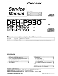
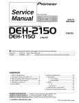
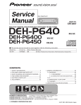
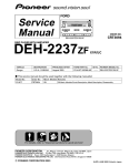
1
Service
Manual
DEQ-P9/UC
ORDER NO.
CRT2686
UNIVERSAL DIGITAL PREAMP EQUALIZER
DEQ-P9
UC,EW
CONTENTS
1.
2.
3.
4.
5.
6.
SAFETY INFORMATION ............................................2
EXPLODED VIEWS AND PARTS LIST .......................2
BLOCK DIAGRAM AND SCHEMATIC DIAGRAM .....6
PCB CONNECTION DIAGRAM ................................16
ELECTRICAL PARTS LIST ........................................24
ADJUSTMENT..........................................................30
7. GENERAL INFORMATION .......................................31
7.1 DIAGNOSIS ........................................................31
7.1.1 DISASSEMBLY .........................................31
7.1.2 CONNECTOR FUNCTION DESCRIPTION .......33
7.2 IC .........................................................................33
7.3 OPERATIONAL DESCRIPTION ..........................41
8. OPERATIONS AND SPECIFICATIONS.....................43
PIONEER CORPORATION
4-1, Meguro 1-Chome, Meguro-ku, Tokyo 153-8654, Japan
PIONEER ELECTRONICS SERVICE INC. P.O.Box 1760, Long Beach, CA 90801-1760 U.S.A.
PIONEER EUROPE NV Haven 1087 Keetberglaan 1, 9120 Melsele, Belgium
PIONEER ELECTRONICS ASIACENTRE PTE.LTD. 253 Alexandra Road, #04-01, Singapore 159936
C PIONEER CORPORATION 2001
K-ZZA. MAY 2001 Printed in Japan
DEQ-P9
1. SAFETY INFORMATION
CAUTION
This service manual is intended for qualified service technicians; it is not meant for the casual do-it-yourselfer.
Qualified technicians have the necessary test equipment and tools, and have been trained to properly and safely repair
complex products such as those covered by this manual.
Improperly performed repairs can adversely affect the safety and reliability of the product and may void the warranty.
If you are not qualified to perform the repair of this product properly and safely, you should not risk trying to do so
and refer the repair to a qualified service technician.
WARNING
This product contains lead in solder and certain electrical parts contain chemicals which are known to the state of
California to cause cancer, birth defects or other reproductive harm.
Health & Safety Code Section 25249.6 - Proposition 65
2. EXPLODED VIEWS AND PARTS LIST
2.1 PACKING
25
26
11
25
24
6
12
4
5
13
22
23
14
8
10
21
9
7
3
1
2
19
17
15
19
20
20
16
18
2
DEQ-P9
NOTE:
- Parts marked by “*” are generally unavailable because they are not in our Master Spare Parts List.
- Screws adjacent to ∇ mark on the product are used for disassembly.
(1) PACKING SECTION PARTS LIST
Mark No. Description
*
*
*
*
*
*
1
2
3
4
5
Part No.
Mark No. Description
Cable
Cord
Cord Assy
Cord
Cord
CDE6690
CDE4167
CDE6643
CDE3951
CDE6641
16
17
18
19
20
6
7
8
9
10
Cord
Polyethylene Bag
Accessory Assy
Polyethylene Bag
Bracket
CDE6644
CEG-145
CEA1849
CEG-020
CNC4763
21
22-1
22-2
22-3
22-4
11
12
13
14
15
Screw Assy
Screw
Screw
Polyethylene Bag
Polyethylene Bag
CEA2761
BMZ40P050FMC
BYC40P120FZK
E36-613
22-5
22-6
* 22-7
23
*
24
See Contrast table(2)
*
*
Carton
Sub Unit Box
Contain Box
Protector
Protector
Polyethylene Bag
Owner’s Manual
Owner’s Manual
Owner’s Manual
Owner’s Manual
Owner’s Manual
Owner’s Manual
Warranty Card
Cover
Lock Tie
25 Clamper
26 Filter
Part No.
See Contrast table(2)
CHG4438
See Contrast table(2)
CHP2359
CHP2360
CEG1116
See Contrast table(2)
See Contrast table(2)
See Contrast table(2)
See Contrast table(2)
See Contrast table(2)
See Contrast table(2)
See Contrast table(2)
CNS2726
See Contrast table(2)
CNV1272
See Contrast table(2)
(2) CONTRAST TABLE
DEQ-P9/UC and EW are constructed the same except for the following:
Mark No.
15
16
18
22-1
22-2
22-3
22-4
22-5
22-6
* 22-7
*
*
Part No.
DEQ-P9/EW
CEG-162
CHG4344
CHL4344
CRB1635
CRB1636
Symbol and Description
Polyethylene Bag
Carton
Contain Box
Owner’s Manual
Owner’s Manual
DEQ-P9/UC
CEG1173
CHG4345
CHL4345
CRB1641
CRB1642
Owner’s Manual
Owner’s Manual
Owner’s Manual
Owner’s Manual
Warranty Card
Not used
Not used
Not used
Not used
CRY1070
CRB1637
CRB1638
CRB1639
CRB1640
CRY1157
Not used
Not used
CNV-754
CTX1060
24 Lock Tie
26 Filter
- Owner's Manual, Installation Manual
Model
DEQ-P9/UC
DEQ-P9/EW
Part No.
CRB1641
CRB1642
CRB1635
CRB1636
CRB1637
CRB1638
CRB1639
CRB1640
Language
English
French
English
Spanish
German
French
Italian
Dutch
3
DEQ-P9
2.2 EXTERIOR
B
A
4
DEQ-P9
- EXTERIOR SECTION PARTS LIST
Mark No. Description
*
*
*
Part No.
Mark No. Description
1 Screw
2 Badge(/UC)
Badge(/EW)
3 Cable
4 Cord Assy
BSZ30P060FZK
CAH1765
CAH1764
CDE6625
CDE6643
24
25
26
27
28
5
6
7
8
9
CEK1001
CNA2366
CNB2636
CNB2634
CNC9165
29 Screw
30 Screw
31 DSP Unit(/UC)
DSP Unit(/EW)
32 Connector(CN1700)
PPZ20P060FZK
PPZ30P080FZK
CWX2519
CWX2520
CKS1956
CNM7103
33
34
35
36
37
Connector(CN1000)
Connector(CN1701)
Connector(CN1702)
Shield
Holder
CKS2191
CKS2198
CKS2201
CNC9164
CNC9175
38
39
40
41
42
Holder
Insulator
Cord
Cord
Filter(/EW)
CNC9176
CNM7106
CDE3951
CDE6641
CTX1054
43 Cushion(/EW)
CNM7567
Fuse(4A)
Chassis
Panel
Case
Case
10 Insulator
11 •••••
12 Audio Control Unit(/UC)
Audio Control Unit(/EW)
13 Connector(CN903)
CWM7506
CWM7507
CDE6309
14
15
16
17
18
Connector(CN603)
Connector(CN501)
Clamper
Fuse(4A)
Pin Jack(CN101)
CDE6462
CDE6463
CEF1007
CEK1001
CKB1048
19
20
21
22
23
Pin Jack(CN301)
Terminal(CN902)
Fuse Holder(CN901)
Connector(CN602)
Connector(CN601)
CKB1048
CKE1033
CKR1021
CKS2248
CKS2601
*
*
Connector(CN604)
Shield
Holder
Holder
Holder
Part No.
CKS3410
CNC4761
CNC9161
CNC9162
CNC9163
5
2
1
3
4
DEQ-P9
3. BLOCK DIAGRAM AND SCHEMATIC DIAGRAM
3.1 BLOCK DIAGRAM
A
B
AUDIO CONTROL UNIT
CN603
CN601
Q601
OPT5V
Q602
1 BUS+
BUS5
1
2
3
4
5
6
7
8
9
10
11
12
13
14
15
16
17
18
18
17
16
15
14
13
12
11
10
9
8
7
6
5
4
3
2
1
CN602
B
CN604
1
2
D+5V
D+5V
OPTION
3
CN1000
1
2
5
6
1
2
IC 601
HA12187FP
8
B MUTE
4
BACC
8
40
A
IP-BUS DRIVER
DSPPW
DIN1
DOUT
23
IPOUT
22
IPIN
STBN
ASENS
21
IPPW
16
asens
IC 602
PD5653A
Q611
Q902
VDD
Q611 Q610
BU
15
bsens
9
reset
XOUT
XIN
DSPCK
DSPOUT
DEEM
DIRPCM
DIRERR
FSD
FS1
FS2
DIRRST
DSPRST
DSPACK
DSPERR
DSPCD
DSPCS1
DSPCS2
DSPCS3
DEST
MUTE
26
24
74
73
72
71
70
69
68
67
66
65
64
63
62
61
76
38
B
CN1700
DSP1
23
24
34
26
27
28
48
3
DEEH
DIRPCM
DIRERR
FS0
FS1
FS2
DIRRST
DIN0
DATAO
16
SDI1
70
DSPCK
71
DSPOUT
IC 1100
TC9331F
15
LRCK
14
BCK
13
CKOUT
65
dsprst
68
dspcs1
69
DSPCD
72
dspack
1
DSP UNIT
IC 1000
LC89055WHS-RA8
A
X1000
12.288MHz
Q604
BU
4
IC 604
TC7S04FU
X601
10.000MHz
BCK
3
1,3,6
RESET
Q611
C
1
IC 603
S-80735ANDZI
2
IC 1003
TC7W34FU
VDD
DSP2
Q603
BCK
1,3,6
Q607 Q608
IC 1002
TC7W34FU
EF902
70
DSPCK
71
DSPOUT
7
1Y
5
2Y
2
3Y
IC 1101
TC9331F
dsprst
dspcs2
DSPCD
dspack
dspeer
LRCK
IC 1006
TC7W34FU
65
68
69
72
22
1,3,6
Q50
EF903
BU
LRCK
Q51
Q52
1,3,6
IC 1005
TC7W34FU
7
1Y
5
2Y
2
3Y
DSP3
C
T66
MCK
EF904
3
Q67
IC 1102
TC9331F
IC 1004
TC7W34FU
Q68
70
DSPCK
71
DSPOUT
EF906
Q53
9 VDD
10
IC 66
TL1451ANS-M
7
Q1702
B
2
VDD
Q86
IC 50
TL5001CPS
1
OUT
4
IN
T86
EF905
Q87
Q1703
Q901
Q54
Q88
A+8V
D+5V
D+5V
A+5V
A-5V
A-8V
CN903
6
7
8
4
2
5
6
7
8
4
2
5
A+8V
D+5V
D+5V
A+5V
A-5V
A-8V
Q1701
Q1700
CN1701
D
6
1
2
3
4
65
dsprst
68
dspcs3
69
DSPCD
72
DSPACK
Q66
5
7
6
8
DEQ-P9
A
DSP1
C 1100
C9331F
DOL
3
1
43
MUTER
42
MUTEL
16
XTI
21
BCKI
19
LRCI
IC 1311
PCM1704U-J
14
CN1702
2
6
IC 1300
SM5847AF
2
DOR
37
DEMPL
36
DEMPR
1
IC 1310
PCM1704U-J
IC 501
PM0017AM
69
DSPCD
72
dspack
20mA/30mA
IC 1313
OPA2134UA
1
7
MID LCH
1
MID RCH
3
CN501
5
6
3
4
7
8
1
3
14
HL
MR
HL
HR
LL
LR
CN101
Q102
Q101
HL
MR
HL
HR
LL
LR
22
21
20
19
18
17
3
5
IC 101
OPA2134UA
1
HL
7
HR
Q202
Q201
5
110mA/130mA
19
DEEM1
20
DEEM2
31
DOR2
30
DOR1
2
6
1
IC 1413
OPA2134UA
1 HIGH LCH
4
7 HIGH RCH
6
14
5
43
MUTER
42
MUTEL
IS62C1024L-70QI
C 1102
C9331F
IC 1511
PCM1704U-J
14
2
6
IC 1500
SM5847AF
65
dsprst
68
dspcs3
69
DSPCD
72
DSPACK
2
DOR
37
DEMPL
36
DEHPR
1
IC 1510
PCM1704U-J
IC 1513
OPA2134UA
1
7
LOW LCH
7
LOW RCH
9
7
9
SL
DOL
21
BCKI
19
LRCI
1
MR
5
8
CN301
39
IC 1105
3
ML
7
Q302
Q301
3
IC 1410
PCM1704U-J
1
4
6
20mA/30mA
DSP3
IC 201
OPA2134UA
14
IC 1400
PD7010A1
12
DSPCK
14
DSPOUT
16
DFST
69
DSPCD
72
dspack
22
dspeer
IC 1411
PCM1704U-J
IC 502
PML011A
C 1101
C9331F
1
IC 301
OPA2134UA
1
LL
7
LR
SR
3
29
5
28
IC 401
OPA2134UA
1
4
Q402
Q401
SL
1
SL
7
SR
5
8
C
Q609
SR
IS62C1024L-70QI
42
BCKI2
41
BCKI1
39
DLRCI
33
DOL2
32
DOL1
BU
38
IC 1104
4
B
3
DSP2
1
C
14
32mA/45mA
MUTE
IC 1600
PCM1716E-3
27
25
16
13
SW LCH
10
SW RCH
12
10
12
BU
MC/DM1
Q905
CN901
701
A
B
2
1
DSPPW
Q904
SYSB
Q903
6
IC 901
TPD1018F
2
3
1
CN902
7
5
6
7
8
D
2
1
3
4
DEQ-P9
3.2 OVERALL CONNECTION DIAGRAM
Note: When ordering service parts, be sure to refer to “EXPLODED VIEWS AND PARTS LIST” or “ELECTRICAL PARTS
LIST”.
IP-BUS=MCD, MDVD
OPTICAL=SCD, OPT-MCD, OPT-DVD
A
FM(100%)(EW): -0.1dBs
FM(100%)(UC): -4.1dBs
AM(30%)(EW):-10.1dBs
AM(30%)(UC):-14.1dBs
IP-BUS: +1.9dBs
OPTICAL: +5.9dBs
C
CN1700
SYSTEM CONTROLLER
B
MODE
DAN202U
D607
DC/DC CONVERTER
4.9V
22µH
22µH
22µH
8.
C
-5.
-8.1V
D
8
A
1
2
3
4
5
7
6
8
DEQ-P9
A
The > mark found on some component parts indicates
the importance of the safety factor of the part.
Therefore, when replacing, be sure to use parts of
identical designation.
PRE-AMPLIFIER
x4
FM(EW):+2.42dBs
FM(UC):+0.42dBs
AM(EW): -5.58dBs
AM(UC): -9.58dBs
IP-BUS:+6.42dBs
OPTICAL:+6.42dBs
A
AUDIO CONTROL UNIT
CN1000
B
RCA OUTPUT
CN1700
CN1702
DSP
UNIT
B
E-VOL
CN1701
FM(EW):+11.42dBs
FM(UC): +9.47dBs
AM(EW): +3.47dBs
AM(UC): -0.53dBs
IP-BUS:+15.47dBs
OPTICAL:+15.47dBs
RCA OUTPUT
E-VOL
8.1V
FM(EW):+10.55dBs
FM(UC): +8.6dBs
AM(EW): +2.6dBs
AM(UC):
-1.4dBs
IP-BUS: +14.6dBs
OPTICAL: +14.6dBs
C
>
-5.1V
FUSE
4A
CEK1001
4700µF/16V
5.1V
14.4V
FUSE
4A CEK1001
>
B.REM
-8.1V
D
NOTE :
Symbol indicates a resistor.
No differentiation is made between chip resistors and
discrete resistors.
Symbol indicates a capacitor.
No differentiation is made between chip capacitors and
discrete capacitors.
5
6
7
Decimal points for resistor
and capacitor fixed values
are expressed as :
2.2 ← 2R2
0.022 ← R022
A
8
9
2
1
3
4
DEQ-P9
3.3 DSP UNIT(GUIDE PAGE)
A-a
A-b
B-a
Large size
SCH diagram
A
A-a
A-a
A-b
Guide page
A-b
OPTICAL IN
Detailed page
CN603
B
DIR.
C
D
CN602
10
B
1
2
3
4
5
7
6
8
DEQ-P9
B-b
B
DSP UNIT
A
x6
B
FM(EW): -0.58dBs
FM(UC): -4.58dBs
AM(EW):-10.58dBs
AM(UC):-14.58dBs
IP-BUS: +1.42dBs
OPTICAL: +5.42dBs
CN501
DAC
DIGITAL
ANALOG
I/V CONVERTER
0V
DF
C
FM(EW): -0.1dBs
FM(UC): -4.1dBs
AM(EW):-10.1dBs
AM(UC):-14.1dBs
IP-BUS: +1.9dBs
OPTICAL: +5.9dBs
8.1V
-8.1V
D
4.9V
-5.1V
CN903
A AUDIO CONTROL UNIT
5
6
7
B
11
8
2
1
3
4
3
4
B-a B-b
A
1
DEQ-P9
B
OPTICAL IN
C
CN603
D
12
B-a
1
2
7
6
8
DEQ-P9
B-a B-b
2
5
A
CN602
B
DIR.
C
D
5
6
7
B-a
8
13
14
1
B-b
1
DAC
x6
B
DIGITAL
ANALOG
DSP UNIT
FM(EW): -0.58dBs
FM(UC): -4.58dBs
AM(EW):-10.58dBs
AM(UC):-14.58dBs
IP-BUS: +1.42dBs
OPTICAL: +5.42dBs
B
A
CN501
B-a B-b
1
DEQ-P9
C
D
2
3
2
3
4
4
2
5
6
7
-5.1V
4.9V
CN903
A AUDIO CONTROL UNIT
FM(EW): -0.1dBs
FM(UC): -4.1dBs
AM(EW):-10.1dBs
AM(UC):-14.1dBs
IP-BUS: +1.9dBs
OPTICAL: +5.9dBs
0V
B-a B-b
6
-8.1V
8.1V
DF
ANALOG
I/V CONVERTER
DIGITAL
5
7
8
DEQ-P9
B-b
15
8
A
B
C
D
2
1
3
4
DEQ-P9
4. PCB CONNECTION DIAGRAM
4.1 AUDIO CONTROL UNIT
A
A
AUDIO CONTROL UNIT
NOTE FOR PCB DIAGRAMS
1. The parts mounted on this PCB
include all necessary parts for
several destination.
For further information for
respective destinations, be sure
to check with the schematic diagram.
2. Viewpoint of PCB diagrams
Connector
Capacitor
SIDE A
RCA OUTPUT
B
P.C.Board
Chip Part
SIDE B
RCA OUTPUT
Fuse
C
Cord Assy
D
16
A
1
2
3
4
5
7
6
8
DEQ-P9
B
B
CN1702
CN1000
SIDE A
B
CN1700
A
IC,Q
MODE
RESET
B
OPTICAL
INPUT
C
IP-BUS INPUT
D
B
5
6
7
CN1701
A
8
17
1
2
3
4
DEQ-P9
A
A
AUDIO CONTROL UNIT
B
C
D
18
A
1
2
3
4
5
6
7
8
DEQ-P9
SIDE B
A
B
C
D
5
6
7
A
8
19
2
1
3
4
DEQ-P9
B
DSP UNIT
4.2 DSP UNIT
A
A
B
CN501
C
D
20
B
1
2
3
4
5
7
6
8
DEQ-P9
A
CN603
SIDE A
IC,Q
A
B
C
D
A
A
5
6
CN602
CN903
7
B
8
21
1
2
3
4
DEQ-P9
B
DSP UNIT
IC,Q
A
B
C
D
22
B
1
2
3
4
5
6
7
8
DEQ-P9
SIDE B
A
B
C
D
5
6
7
B
8
23
DEQ-P9
5. ELECTRICAL PARTS LIST
NOTES:
- Parts whose parts numbers are omitted are subject to being not supplied.
- The part numbers shown below indicate chip components.
Chip Resistor
RS1/_S___J,RS1/__S___J
Chip Capacitor (except for CQS.....)
CKS....., CCS....., CSZS.....
=====Circuit Symbol and No.===Part Name
--- -----------------------------------------------
A
Part No.
-------------------------
Unit Number : CWM7506(DEQ-P9/UC)
Unit Number : CWM7507(DEQ-P9/EW)
Unit Name
: Audio Control Unit
MISCELLANEOUS
IC
IC
IC
IC
IC
50
66
101
201
301
IC
IC
IC
IC
IC
TL5001CPS
TL1451ANS-M
OPA2134UA
OPA2134UA
OPA2134UA
IC
IC
IC
IC
IC
401
501
502
601
602
IC
IC
IC
IC
IC
OPA2134UA
PM0017AM
PML011A
HA12187FP
PD5653A
IC
IC
IC
Q
Q
603
604
901
50
51
IC
IC
IC
Transistor
Transistor
S-80735ANDZI
TC7S04FU
TPD1018F
2SA1797
2SC2812
Q
Q
Q
Q
Q
52
53
54
66
67
Transistor
Transistor
Transistor
Transistor
Transistor
2SA1179
2SA1179
DTC124EK
2SA1797
2SC2812
Q
Q
Q
Q
Q
68
86
87
88
101
Transistor
Transistor
Transistor
Transistor
Transistor
2SA1179
2SA1797
2SC2812
2SA1179
IMX9
Q
Q
Q
Q
Q
102
201
202
301
302
Transistor
Transistor
Transistor
Transistor
Transistor
IMX9
IMX9
IMX9
IMX9
IMX9
Q
Q
Q
Q
Q
401
402
601
602
603
Transistor
Transistor
Transistor
Transistor
Transistor
IMX9
IMX9
2SB1238
2SC2712
2SC2712
Q
Q
Q
Q
Q
604
605
606
607
608
Transistor
Transistor
Transistor
Transistor
Transistor
IMD2A
2SC2712
2SC2412K
2SC2412K
2SC2412K
Q
Q
Q
Q
Q
609
610
611
901
902
Transistor
Transistor
Transistor
Transistor
Transistor
IMD2A
DTA124EU
2SC2412K
2SB1243
2SD1760F5
24
=====Circuit Symbol and No.===Part Name
--- -----------------------------------------------
Part No.
-------------------------
Q
Q
Q
D
D
903
904
905
50
66
Transistor
Transistor
Transistor
Diode
Diode
2SC2412K
DTC114EK
2SB1238
D2FS6
SC802-06
D
D
D
D
D
86
101
102
201
202
Diode
Diode
Diode
Diode
Diode
SC802-06
DAP202U
DAP202U
DAP202U
DAP202U
D
D
D
D
D
301
302
401
402
601
Diode
Diode
Diode
Diode
Diode
DAP202U
DAP202U
DAP202U
DAP202U
MA152K
D
D
D
D
D
602
603
604
605
606
Diode
Diode
Diode
Diode
Diode
DAN202U
DAN202U
DAN202U
DAN202U
HZS7L(C2)
D
D
D
D
D
607
901
902
903
904
Diode
Diode
Diode
Diode
Diode
DAN202U
HZS6L(B1)
HZS6L(B1)
ERA15-02VH
DAN202U
D
D
D
D
D
905
906
907
908
909
Diode
Diode
Diode
Diode
Diode
HZS9L(A2)
MA111
ERA15-02VH
ERA15-02VH
ERA15-02VH
L
L
L
L
L
50
51
52
66
67
Choke Coil 22µH
Choke Coil 22µH
Choke Coil 22µH
Coil
Coil
CTH1109
CTH1109
CTH1109
CTH1110
CTH1110
L
L
L
L
L
86
87
601
602
603
Coil
Coil
Inductor
Inductor
Inductor
CTH1110
CTH1110
LAU1R5K
LAU3R3K
CTF1410
L
L
L
L
L
604
605
606
607
608
Inductor-Array
Inductor-Array
Inductor-Array
Inductor-Array
Inductor
CTF1421
CTF1421
CTF1421
CTF1421
CTF1410
L
T
T
X
S
901
66
86
601
601
Coil (DEQ-P9/EW)
Transformer
Transformer
Radiator 10.00MHz
Switch(RESET)
CTH1170
CTT1098
CTT1098
CSS1428
CSG1059
S
EF
EF
EF
EF
602
901
902
903
904
Slide Switch(MODE)
EMI Filter
EMI Filter
EMI Filter
EMI Filter
CSH1051
CCG1003
CCG1083
CCG1083
CCG1083
DEQ-P9
=====Circuit Symbol and No.===Part Name
--- -----------------------------------------------
Part No.
-------------------------
=====Circuit Symbol and No.===Part Name
--- -----------------------------------------------
Part No.
-------------------------
EF
EF
CCG1083
CCG1083
R
R
R
R
R
210
211
212
213
214
RS1/16S103J
RN1/10SE4700D
RN1/10SE4700D
RS1/16S103J
RS1/16S103J
R
R
R
R
R
215
216
301
302
303
RN1/10SE2202D
RN1/10SE2202D
RN1/10SE1002D
RN1/10SE1002D
RN1/10SE1201D
R
R
R
R
R
304
305
306
307
308
RN1/10SE1201D
RN1/10SE2201D
RN1/10SE2201D
RS1/16S103J
RS1/16S103J
R
R
R
R
R
309
310
311
312
313
RN1/10SE4700D
RN1/10SE4700D
RN1/10SE4700D
RN1/10SE4700D
RS1/16S103J
R
R
R
R
R
314
315
316
401
402
RS1/16S103J
RN1/10SE2202D
RN1/10SE2202D
RN1/10SE1002D
RN1/10SE1002D
R
R
R
R
R
403
404
405
406
407
RN1/10SE1002D
RN1/10SE1002D
RN1/10SE1202D
RN1/10SE1202D
RS1/16S103J
R
R
R
R
R
408
409
410
411
412
RS1/16S103J
RN1/10SE4700D
RN1/10SE4700D
RN1/10SE4700D
RN1/10SE4700D
R
R
R
R
R
413
414
415
416
501
RS1/16S103J
RS1/16S103J
RN1/10SE2202D
RN1/10SE2202D
RS1/16S682J
R
R
R
R
R
502
503
504
602
603
RS1/16S103J
RS1/16S103J
RS1/16S153J
RS1/16S472J
RS1/16S101J
R
R
R
R
R
605
606
607
608
609
RS1/16S101J
RS1/16S102J
RS1/10S103J
RS1/16S103J
RS1/10S472J
R
R
R
R
R
610
611
612
613
614
RS1/16S102J
RS1/10S472J
RS1/10S103J
RS1/16S473J
RS1/16S473J
R
R
R
R
R
615
616
617
618
620
RS1/16S473J
RS1/16S102J
RAB4C471J
RS1/16S473J
RS1/16S473J
R
R
R
R
R
621
622
623
624
625
RAB4C473J
RS1/16S473J
RS1/16S102J
RS1/16S822J
RS1/16S473J
905
906
EMI Filter
EMI Filter
RESISTORS
R
R
R
R
R
49
50
51
52
53
RS1/4S751J
RS1/10S122J
RS1/10S123J
RS1/4S751J
RS1/10S101J
R
R
R
R
R
54
55
56
57
58
RN1/10SE1002D
RN1/10SE3001D
RS1/10S104J
RN1/10SE2202D
RS1/10S474J
R
R
R
R
R
59
60
61
62
63
RS1/10S333J
RS1/10S221J
RS1/10S221J
RS1/10S473J
RS1/10S223J
R
R
R
R
R
64
66
67
68
69
RN1/10SE2201D
RS1/10S122J
RS1/10S103J
RS1/4S102J
RS1/10S101J
R
R
R
R
R
70
71
72
73
74
RN1/10SE3002D
RN1/10SE6201D
RS1/4S102J
RN1/10SE1002D
RN1/10SE1002D
R
R
R
R
R
75
76
77
78
80
RS1/10S474J
RN1/10SE9101D
RN1/10SE1502D
RN1/10SE2702D
RN1/10SE1002D
R
R
R
R
R
81
82
86
87
88
RN1/10SE1002D
RN1/10SE4301D
RS1/10S122J
RS1/10S103J
RS1/4S102J
R
R
R
R
R
89
90
91
92
93
RS1/10S101J
RN1/10SE3002D
RN1/10SE4301D
RN1/10SE2401D
RS1/4S102J
R
R
R
R
R
101
102
103
104
105
RN1/10SE1002D
RN1/10SE1002D
RN1/10SE1201D
RN1/10SE1201D
RN1/10SE2201D
R
R
R
R
R
106
107
108
109
110
RN1/10SE2201D
RN1/10SE4700D
RS1/16S103J
RS1/16S103J
RN1/10SE4700D
R
R
R
R
R
111
112
113
114
115
RN1/10SE4700D
RN1/10SE4700D
RS1/16S103J
RS1/16S103J
RN1/10SE2202D
R
R
R
R
R
116
201
202
203
204
RN1/10SE2202D
RN1/10SE1002D
RN1/10SE1002D
RN1/10SE1201D
RN1/10SE1201D
R
R
R
R
R
205
206
207
208
209
RN1/10SE2201D
RN1/10SE2201D
RN1/10SE4700D
RN1/10SE4700D
RS1/16S103J
25
DEQ-P9
=====Circuit Symbol and No.===Part Name
--- -----------------------------------------------
Part No.
-------------------------
=====Circuit Symbol and No.===Part Name
--- -----------------------------------------------
Part No.
-------------------------
R
R
R
R
R
626
627
628
629
630
RS1/16S103J
RS1/16S103J
RS1/16S103J
RS1/16S222J
RS1/16S473J
C
C
C
C
C
102
103
104
105
106
CFHSQ221J50
CCH1396
CCH1396
CCSRCH471J50
CCSRCH471J50
R
R
R
R
R
631
632
633
634
635
RS1/16S103J
RS1/16S473J
RS1/16S101J
RS1/16S473J
RS1/16S473J
C
C
C
C
C
107
109
111
112
201
R
R
R
R
R
636
637
638
639
640
RS1/16S104J
RS1/16S473J
RS1/16S473J
RS1/16S222J
RS1/16S472J
C
C
C
C
C
202
203
204
205
206
R
R
R
R
R
641
642
644
901
902
RS1/16S473J
RS1/16S473J
RS1/16S103J
RS1/16S102J
RS1/16S223J
C
C
C
C
C
207
208
211
212
301
R
R
R
R
R
903
904
905
906
907
RS1/16S103J
RS1/16S473J
RS1/16S473J
RD1/4PU222J
RS1/16S473J
C
C
C
C
C
302
303
304
305
306
R
R
R
908
909
910
RS1/16S102J
RAB4C102J
RAB4C102J
C
C
C
C
C
307
308
311
312
401
CAPACITORS
10µF/16V
10µF/16V
10µF/16V
10µF/16V
10µF/16V
10µF/16V
10µF/16V
10µF/16V
10µF/16V
10µF/16V
10µF/16V
10µF/16V
CCH1396
CCH1396
CKSRYB104K25
CKSRYB104K25
CFHSQ221J50
CFHSQ221J50
CCH1396
CCH1396
CCSRCH471J50
CCSRCH471J50
CCH1396
CCH1396
CKSRYB104K25
CKSRYB104K25
CFHSQ221J50
CFHSQ221J50
CCH1396
CCH1396
CCSRCH471J50
CCSRCH471J50
CCH1396
CCH1396
CKSRYB104K25
CKSRYB104K25
CFHSQ221J50
C
C
C
C
C
50
52
54
55
56
CEHAZL680M16
CEHAZL680M16
CCSRCH331J50
CKSRYB102K50
CEHAZL680M16
C
C
C
C
C
402
403
404
405
406
C
C
C
C
C
58
59
60
61
62
CEHAZL680M16
CKSRYB102K50
CKSRYB473K25
CKSRYB102K50
CKSRYB104K25
C
C
C
C
C
407
408
411
412
501
C
C
C
C
C
66
68
70
71
72
CEHAZL680M16
CEHAZL680M16
CKSRYB102K50
CKSRYB102K50
CEHAZL680M16
C
C
C
C
C
502
503
504
505
506
C
C
C
C
C
73
74
75
76
77
CEHAZL680M16
CEHAZL680M16
CKSRYB102K50
CKSRYB222K50
CKSRYB223K25
C
C
C
C
C
507
508
509
510
511
4R7µF/35V
4R7µF/35V
CCH1358
CCH1358
CKSRYB104K25
CEJQ100M16
CEJQ100M16
C
C
C
C
C
78
79
80
81
82
CCSRCH221J50
CKSRYB104K25
CKSRYB102K50
CKSRYB102K50
CEHAS1R0M50
C
C
C
C
C
512
513
514
515
516
4R7µF/35V
4R7µF/35V
47µF/25V
CCH1358
CCH1358
CCH1394
CKSRYB104K25
CCH1394
C
C
C
C
C
86
88
90
91
92
CEHAZL680M16
CEHAZL680M16
CKSRYB102K50
CKSRYB102K50
CEHAZL680M16
C
C
C
C
C
517
518
601
602
603
C
C
C
C
C
93
94
95
97
101
CEHAZL680M16
CEHAZL680M16
CKSRYB102K50
CKSRYB223K25
CFHSQ221J50
C
C
C
C
C
604
605
606
607
608
26
10µF/16V
10µF/16V
10µF/16V
10µF/16V
CFHSQ221J50
CCH1396
CCH1396
CCSRCH471J50
CCSRCH471J50
100µF/16V
CCH1396
CCH1396
CKSRYB104K25
CKSRYB104K25
CCH1353
4R7µF/35V
4R7µF/35V
4R7µF/35V
4R7µF/35V
CKSRYB104K25
CCH1358
CCH1358
CCH1358
CCH1358
47µF/25V
47µF/25V
CKSRYB104K25
CCH1394
CKSRYB104K25
CKSRYB104K25
CKSRYB473K25
CCSRCH101J50
CCSRCH101J50
CEJQ2R2M50
CKSRYB104K25
CCSRCH101J50
DEQ-P9
=====Circuit Symbol and No.===Part Name
--- -----------------------------------------------
Part No.
-------------------------
=====Circuit Symbol and No.===Part Name
--- -----------------------------------------------
Part No.
-------------------------
C
C
C
C
C
609
901
902
903
904
CEJQ470M16
CCH1394
CKSRYB473K25
CEJQ470M10
CCH1353
D
D
D
D
D
1401
1402
1410
1411
1412
Diode Network
Diode
Diode Network
Diode Network
Diode Network
DA204U
MA111
DA204U
DA204U
DA204U
C
C
C
C
C
905
906
907
908
909
CCH1353
CCL1016
CEJQ101M6R3
CKSRYB473K25
CEJQ470M16
D
D
D
D
D
1413
1500
1501
1510
1511
Diode Network
Diode Network
Diode Network
Diode Network
Diode Network
DA204U
DA204U
DA204U
DA204U
DA204U
C
C
C
C
C
910
911
912
913
914
CEJQ470M16
CKSRYB473K25
CKSRYB104K25
CCH1266
CKSRYB103K50
D
D
D
D
D
1512
1513
1600
1601
1700
Diode Network
Diode Network
Diode Network
Diode Network
Diode
DA204U
DA204U
DA204U
DA204U
MA111
C
C
C
915
916
917
CCH1395
CKSRYB223K50
CCSQCH101J50
L
L
L
L
L
1000
1002
1003
1004
1005
Inductor
Inductor
Inductor
Inductor
Inductor
CTF1295
LCTA1R0J4532
LCTA1R0J4532
CTF1306
CTF1306
L
L
L
L
L
1006
1007
1008
1100
1101
Inductor
Inductor
Inductor
Inductor
Inductor
CTF1306
CTF1306
CTF1306
CTF1295
CTF1295
L
L
L
L
L
1102
1103
1104
1105
1106
Inductor
Inductor
Inductor
Inductor-Array
Inductor-Array
CTF1295
CTF1295
CTF1295
CTF1421
CTF1421
L
L
L
L
L
1107
1108
1109
1110
1111
Inductor-Array
Inductor-Array
Inductor-Array
Inductor-Array
Inductor
CTF1421
CTF1421
CTF1421
CTF1421
CTF1306
L
L
L
L
L
1112
1113
1114
1115
1116
Inductor
Inductor-Array
Inductor-Array
Inductor-Array
Inductor-Array
CTF1306
CTF1421
CTF1421
CTF1421
CTF1421
L
L
L
L
L
1117
1118
1300
1310
1311
Inductor-Array
Inductor-Array
Inductor
Inductor
Inductor
CTF1421
CTF1421
CTF1295
CTF1295
CTF1295
L
L
L
L
L
1312
1313
1314
1315
1316
Inductor
Inductor
Inductor
Inductor (DEQ-P9/EW)
Inductor (DEQ-P9/EW)
CTF1295
CTF1295
CTF1295
CTF1295
CTF1295
L
L
L
L
L
1400
1410
1411
1412
1413
Inductor
Inductor
Inductor
Inductor
Inductor
LCTA1R0J4532
CTF1295
CTF1295
CTF1295
CTF1295
L
L
L
L
L
1414
1415
1416
1500
1510
Inductor
Inductor (DEQ-P9/EW)
Inductor (DEQ-P9/EW)
Inductor
Inductor
CTF1295
CTF1295
CTF1295
CTF1295
CTF1295
L
L
L
L
L
1511
1512
1513
1514
1515
Inductor
Inductor
Inductor
Inductor
Inductor (DEQ-P9/EW)
CTF1295
CTF1295
CTF1295
CTF1295
CTF1295
B
47µF/25V
100µF/16V
100µF/16V
0.47F/5.5V
4700µF/16V
100µF/16V
Unit Number : CWX2519(DEQ-P9/UC)
Unit Number : CWX2520(DEQ-P9/EW)
Unit Name
: DSP Unit
MISCELLANEOUS
IC
IC
IC
IC
IC
1000
1002
1003
1004
1005
IC
IC
IC
IC
IC
LC89055WHS-RA8
TC7W34FU
TC7W34FU
TC7W34FU
TC7W34FU
IC
IC
IC
IC
IC
1006
1100
1101
1102
1104
IC
IC
IC
IC
IC
TC7W34FU
TC9331F
TC9331F
TC9331F
IS62C1024L-70QI
IC
IC
IC
IC
IC
1105
1300
1310
1311
1313
IC
IC
IC
IC
IC
IS62C1024L-70QI
SM5847AF
PCM1704U-J
PCM1704U-J
OPA2134UA
IC
IC
IC
IC
IC
1400
1410
1411
1413
1500
IC
IC
IC
IC
IC
PD7010A1
PCM1704U-J
PCM1704U-J
OPA2134UA
SM5847AF
IC
IC
IC
IC
Q
1510
1511
1513
1600
1000
IC
IC
IC
IC
Transistor
PCM1704U-J
PCM1704U-J
OPA2134UA
PCM1716E-3
2SC2712
Q
Q
Q
Q
D
1700
1701
1702
1703
1000
Chip Transistor
Chip Transistor
Transistor
Transistor
Diode
2SC2712
2SC2712
DTC144TK
DTC144TK
MA111
D
D
D
D
D
1001
1002
1100
1300
1301
Diode Network
Diode Network
Diode
Diode Network
Diode Network
DA204U
DA204U
MA152WK
DA204U
DA204U
D
D
D
D
D
1310
1311
1312
1313
1400
Diode Network
Diode Network
Diode Network
Diode Network
Diode Network
DA204U
DA204U
DA204U
DA204U
DA204U
27
DEQ-P9
=====Circuit Symbol and No.===Part Name
--- -----------------------------------------------
Part No.
-------------------------
=====Circuit Symbol and No.===Part Name
--- -----------------------------------------------
Part No.
-------------------------
L
L
L
L
L
1516
1600
1601
1602
1603
Inductor (DEQ-P9/EW)
Inductor
Inductor
Inductor (DEQ-P9/EW)
Inductor (DEQ-P9/EW)
CTF1295
CTF1295
CTF1295
CTF1295
CTF1295
R
R
R
R
R
1123
1124
1125
1126
1127
RS1/16S331J
RS1/16S0R0J
RS1/16S0R0J
RS1/16S0R0J
RS1/16S0R0J
L
L
L
L
L
1700
1701
1702
1703
1704
Inductor
Inductor
Inductor-Array
Inductor-Array
Inductor-Array
CTF1306
CTF1306
CTF1421
CTF1421
CTF1421
R
R
R
R
R
1128
1129
1130
1133
1134
RS1/16S0R0J
RS1/16S0R0J
RAB4C473J
RAB4C473J
RS1/16S0R0J
L
L
X
X
X
1705
1706
1000
1100
1101
Inductor-Array
Inductor
Crystal Resonator 12.288MHz
Crystal Resonator 32.0MHz
Crystal Resonator 32.0MHz
CTF1421
CTF1250
CSS1416
CSS1360
CSS1360
R
R
R
R
R
1135
1136
1137
1138
1139
RS1/16S0R0J
RS1/16S0R0J
RS1/16S0R0J
RS1/16S0R0J
RS1/16S0R0J
X
EF
EF
EF
EF
1102
1700
1701
1702
1703
Crystal Resonator 32.0MHz
EMI Filter
EMI Filter
EMI Filter
EMI Filter
CSS1360
CCG1030
CCG1030
CCG1030
CCG1030
R
R
R
R
R
1140
1141
1142
1143
1300
RS1/16S0R0J
RS1/16S0R0J
RS1/16S0R0J
RS1/16S0R0J
RAB4C101J
R
R
R
R
R
1301
1302
1303
1310
1311
RS1/16S820J
RS1/16S0R0J
RS1/16S102J
RAB4C470J
RAB4C470J
R
R
R
R
R
1312
1313
1314
1315
1316
RN1/10SE1801D
RN1/10SE1801D
RN1/10SE2200D
RN1/10SE2200D
RN1/10SE4701D
R
R
R
R
R
1317
1318
1319
1400
1401
R
R
R
R
R
1402
1403
1410
1411
1412
RS1/16S102J
RAB4C101J
RAB4C470J
RAB4C470J
RN1/10SE1801D
R
R
R
R
R
1413
1414
1415
1416
1417
RN1/10SE1801D
RN1/10SE2200D
RN1/10SE2200D
RN1/10SE4701D
RN1/10SE4701D
R
R
R
R
R
1418
1419
1500
1502
1503
R
R
R
R
R
1504
1510
1511
1512
1513
RS1/16S102J
RAB4C470J
RAB4C470J
RN1/10SE1801D
RN1/10SE1801D
R
R
R
R
R
1514
1515
1516
1517
1518
RN1/10SE2200D
RN1/10SE2200D
RN1/10SE4701D
RN1/10SE4701D
RS1/10S0R0J
R
R
R
R
R
1519
1600
1601
1602
1603
RESISTORS
R
R
R
R
R
1000
1003
1007
1008
1011
RS1/16S103J
RN1/10SE1001D
RN1/10SE1001D
RN1/10SE4702D
RN1/10SE1002D
R
R
R
R
R
1012
1016
1017
1018
1019
RN1/10SE1001D
RN1/10SE5101D
RN1/10SE4700D
RN1/10SE7501D
RN1/10SC75R0D
R
R
R
R
R
1021
1022
1023
1024
1025
RS1/16S471J
RAB4C101J
RS1/16S105J
RN1/10SE1000D
RN1/10SE1000D
R
R
R
R
R
1026
1027
1028
1029
1030
RN1/10SE2200D
RN1/10SE1000D
RN1/10SE2200D
RN1/10SE1000D
RN1/10SE1000D
R
R
R
R
R
1033
1038
1041
1042
1043
RN1/10SE1200D
RN1/10SE1000D
RN1/10SE2200D
RN1/10SE2200D
RN1/10SE1000D
R
R
R
R
R
1044
1100
1105
1106
1107
RN1/10SE1200D
RAB4C471J
RAB4C471J
RAB4C473J
RS1/16S105J
R
R
R
R
R
1108
1109
1110
1111
1112
RS1/16S331J
RS1/16S0R0J
RS1/16S0R0J
RS1/16S0R0J
RS1/16S0R0J
R
R
R
R
R
1113
1114
1115
1116
1117
RS1/16S0R0J
RAB4C471J
RAB4C471J
RAB4C471J
RAB4C471J
R
R
R
R
R
1118
1119
1120
1121
1122
RAB4C473J
RAB4C473J
RS1/16S105J
RS1/16S105J
RS1/16S331J
28
(DEQ-P9/UC)
(DEQ-P9/UC)
(DEQ-P9/UC)
(DEQ-P9/UC)
(DEQ-P9/UC)
(DEQ-P9/UC)
RN1/10SE4701D
RS1/10S0R0J
RS1/10S0R0J
RS1/16S0R0J
RS1/16S0R0J
RS1/10S0R0J
RS1/10S0R0J
RS1/16S101J
RAB4C101J
RS1/16S0R0J
RS1/10S0R0J
RAB4C101J
RS1/16S0R0J
RS1/16S102J
RS1/16S102J
DEQ-P9
=====Circuit Symbol and No.===Part Name
--- -----------------------------------------------
Part No.
-------------------------
=====Circuit Symbol and No.===Part Name
--- -----------------------------------------------
Part No.
-------------------------
R
R
R
R
R
1610
1611
1612
1613
1614
RN1/10SE2200D
RN1/10SE2200D
RN1/10SE4701D
RN1/10SE4701D
RS1/10S0R0J
C
C
C
C
C
1134
1136
1138
1140
1141
CKSRYB473K25
CKSRYB102K50
CKSRYB473K25
CKSRYB473K25
CKSRYB102K50
R
R
R
R
R
1615
1700
1703
1704
1705
RS1/10S0R0J
RAB4C473J
RS1/16S103J
RS1/16S103J
RS1/16S102J
C
C
C
C
C
1142
1143
1144
1146
1300
CKSRYB473K25
CKSRYB473K25
CKSRYB473K25
CKSRYB473K25
CKSRYB104K25
R
R
1706
1707
RS1/16S473J
RS1/16S472J
C
C
C
C
C
1301
1302
1303
1304
1305
CKSRYB104K25
CKSRYB104K25
CCSRCH331J50
CKSRYB104K25
CKSRYB104K25
C
C
C
C
C
1306
1307
1308
1309
1310
CEZA330M16
CKSRYB473K25
CKSRYB104K25
CKSRYB473K25
CASA220M10
C
C
C
C
C
1311
1312
1313
1314
1315
CASA220M10
CASA220M10
CASA220M10
CKSRYB104K25
CKSRYB104K25
C
C
C
C
C
1316
1317
1318
1319
1320
CKSRYB104K25
CKSRYB104K25
CEZA220M25
CEZA220M25
CEZA101M10
C
C
C
C
C
1321
1322
1323
1324
1325
CEZA101M10
CKSRYB104K25
CKSRYB104K25
CEZA470M10
CEZA470M10
C
C
C
C
C
1326
1327
1328
1329
1330
CKSRYB104K25
CKSRYB104K25
CEZA470M10
CEZA470M10
CEZA470M10
C
C
C
C
C
1331
1332
1333
1334
1335
CEZA470M10
CKSRYB104K25
CKSRYB104K25
CCH1352
CCH1352
C
C
C
C
C
1336
1337
1338
1339
1400
CFHSQ331J50
CFHSQ331J50
CFHSQ332J16
CFHSQ332J16
CCSRCH331J50
C
C
C
C
C
1401
1402
1405
1410
1411
CEZA330M16
CKSRYB473K25
CKSRYB473K25
CASA220M10
CASA220M10
C
C
C
C
C
1412
1413
1414
1415
1416
CASA220M10
CASA220M10
CKSRYB104K25
CKSRYB104K25
CKSRYB104K25
C
C
C
C
C
1417
1418
1419
1420
1421
CKSRYB104K25
CEZA220M25
CEZA220M25
CEZA101M10
CEZA101M10
(DEQ-P9/UC)
(DEQ-P9/UC)
CAPACITORS
C
C
C
C
C
1000
1010
1011
1012
1013
CKSRYB104K25
CKSRYB103K50
CKSRYB104K25
CKSRYB104K25
CFHSQ103J16
C
C
C
C
C
1014
1015
1017
1018
1019
CFHSP104J16
CFHSP104J16
CFHSQ103J16
CKSRYB104K25
CKSRYB473K25
C
C
C
C
C
1020
1021
1022
1023
1024
CKSRYB473K25
CEZA100M16
CEZA100M16
CCSRCH270J50
CKSRYB473K25
C
C
C
C
C
1025
1026
1027
1028
1029
CKSRYB473K25
CEZA470M10
CCSRCH330J50
CEZA470M10
CKSRYB473K25
C
C
C
C
C
1030
1043
1044
1045
1046
CKSRYB473K25
CKSRYB473K25
CKSRYB473K25
CKSRYB473K25
CKSRYB473K25
C
C
C
C
C
1047
1048
1049
1050
1103
CKSRYB473K25
CKSRYB473K25
CKSRYB473K25
CKSRYB473K25
CKSRYB473K25
C
C
C
C
C
1104
1107
1108
1109
1110
CCSRCH100D50
CEJQ470M6R3
CCSRCH100D50
CKSRYB473K25
CKSRYB102K50
C
C
C
C
C
1112
1114
1119
1120
1121
CKSRYB473K25
CKSRYB473K25
CKSRYB473K25
CKSRYB473K25
CCSRCH100D50
C
C
C
C
C
1122
1123
1124
1125
1126
CKSRYB473K25
CKSRYB473K25
CCSRCH100D50
CEJQ100M16
CEJQ470M6R3
C
C
C
C
C
1127
1128
1129
1130
1132
CCSRCH100D50
CEJQ100M16
CEJQ470M6R3
CCSRCH100D50
CKSRYB473K25
10µF/16V
10µF/16V
29
DEQ-P9
=====Circuit Symbol and No.===Part Name
--- -----------------------------------------------
Part No.
-------------------------
=====Circuit Symbol and No.===Part Name
--- -----------------------------------------------
Part No.
-------------------------
C
C
C
C
C
1422
1423
1424
1425
1426
CKSRYB104K25
CKSRYB104K25
CEZA470M10
CEZA470M10
CKSRYB104K25
C
C
C
C
C
1522
1523
1524
1525
1526
CKSRYB104K25
CKSRYB104K25
CEZA470M10
CEZA470M10
CKSRYB104K25
C
C
C
C
C
1427
1428
1429
1430
1431
CKSRYB104K25
CEZA470M10
CEZA470M10
CEZA470M10
CEZA470M10
C
C
C
C
C
1527
1528
1529
1530
1531
CKSRYB104K25
CEZA470M10
CEZA470M10
CEZA470M10
CEZA470M10
C
C
C
C
C
1432
1433
1434
1435
1436
CKSRYB104K25
CKSRYB104K25
CCH1352
CCH1352
CFHSQ331J50
C
C
C
C
C
1532
1533
1534
1535
1536
CKSRYB104K25
CKSRYB104K25
CCH1352
CCH1352
CFHSQ331J50
C
C
C
C
C
1437
1438
1439
1500
1501
CFHSQ331J50
CFHSQ332J16
CFHSQ332J16
CKSRYB104K25
CKSRYB104K25
C
C
C
C
C
1537
1538
1539
1600
1601
CFHSQ331J50
CFHSQ332J16
CFHSQ332J16
CKSRYB104K25
CEZA100M16
C
C
C
C
C
1502
1503
1504
1505
1506
CKSRYB104K25
CCSRCH331J50
CKSRYB104K25
CKSRYB104K25
CEZA330M16
C
C
C
C
C
1602
1603
1604
1605
1606
CKSRYB104K25
CEZA100M16
CEZA100M16
CKSRYB104K25
CEZA100M16
C
C
C
C
C
1507
1508
1509
1510
1511
CKSRYB473K25
CKSRYB473K25
CKSRYB104K25
CASA220M10
CASA220M10
C
C
C
C
C
1607
1608
1609
1610
1611
CEZA100M16
CEZA100M16
CKSRYB104K25
CCSRCH331J50
CCH1396
C
C
C
C
C
1512
1513
1514
1515
1516
CASA220M10
CASA220M10
CKSRYB104K25
CKSRYB104K25
CKSRYB104K25
C
C
C
C
C
1612
1613
1614
1700
1701
C
C
C
C
C
1517
1518
1519
1520
1521
CKSRYB104K25
CEZA220M25
CEZA220M25
CEZA101M10
CEZA101M10
10µF/16V
10µF/16V
6. ADJUSTMENT
There is no information to be shown in this chapter.
30
10µF/16V
10µF/16V
10µF/16V
10µF/16V
47µF/25V
47µF/25V
CCH1396
CFHSQ103J16
CFHSQ103J16
CCH1394
CCH1394
DEQ-P9
7. GENERAL INFORMATION
7.1 DIAGNOSIS
7.1.1 DISASSEMBLY
- Removing the Case (Fig.1)
Case
Remove the eleven screws and then remove
the Case.
Fig.1
- Removing the DSP Section (Fig.2)
Remove the four screws.
Disconnect the connector and then remove the DSP
Section.
DSP Section
Fig.2
31
DEQ-P9
- Removing the DSP Unit (Fig.3)
After solder is removed, straight the tabs at
five locations indicated and then remove
the DSP Unit.
DSP Unit
Fig.3
- Removing the Audio Control Unit (Fig.4)
Remove the three screws.
Straight the tabs at five locations indicated
and then remove the Audio Control Unit.
Fig.4
Audio Control Unit
32
DEQ-P9
7.1.2 CONNECTOR FUNCTION DESCRIPTION
IP-BUS
INPUT
1
2
3
4
5
6
8
9
10
7
11
1. BUS+
2. GND
3. GND
4. NC
5. BUS6. GND
7. BUS L+ INPUT
8. ASENB
9. BUS R+ INPUT
10. BUS R- INPUT
11. BUS L- INPUT
OPTICAL
INPUT
3
4
1
2
1. GND
2. GND
3. NC
4. OPTOUT
7.2 IC
8
7
6
+INB
-INB
* PM0017AM
OUTB
V+
OPA2134UA
A GND
1
24
AVCC
VREF
2
23
DVCC
IN1
3
22
OUT1
IN2
4
21
OUT2
IN3
5
20
OUT3
IN4
6
19
OUT4
IN5
7
18
OUT5
IN6
8
17
OUT6
NC
9
16
NC
NC 10
15
DATA
CT 11
14
CLK
D GND 12
13
STB
5
+
1
2
3
4
OUTA
-INA
+INA
V-
+
IC's marked by * are MOS type.
Be careful in handling them because they are very
liable to be damaged by electrostatic induction.
33
DEQ-P9
SIGGN D
2
Out1R
Out2L
Out2R
ADCVDDREF
In 1L
In 1R
In 2L
In 2R
In 3L
In 3R
43
42
41
40
39
38
37
36
35
34
33 MUTE
VDD
1
44
GND
V33
Out1L
PML011A
32 SDA
Reference-voltagegenerator
Level-selector
3
CODEC- IF
CassR
(4ch independent control)
DC: 4.15V % 1.65V
AC: 2Vr ms%0.8Vr ms
4
Output-selector
Bypass
-gain
*b
CDL +
31 SCL
*b
bypass line
Zero-cross logic
(6ch independent contr ol )
CassL
BypassSelector
Input -gain-adjuster
5
(4-inputs independent-control)
30 SEL
29 SPKR1L
Zero-cross detect
CD-
Digital-control
(6ch independent control)
Input-source-selector
6
(4-inputs independent-control)
Volume
27 SPKR2L
SPKR3R
SPKR3L
SPKR2R
SPKR2L
SPKR1R
Linedriv er-amplifier
*b
SPKR1L
Quasi differential
stereo input circuit
differential mono
input circuit
differential mono
input circuit
level-shift
level-shift
envelope-detector
7
Quasi differential
stereo input circuit
CDR+
28 SPKR1R
Mix
(6ch independent control)
26 SPKR2R
11
23 OUTPUTREF
14
15
16
17
18
19
GND
13
AM-IF
12
20
21
22
PGND
Navi+
VCC
24 SPKR3R
VDD
10
MPX-RDS
Navi-
AM
25 SPKR3L
Tuner-
9
FM
Phone-
FM -level
8
AM-level
Phone+
* PD5653A
40
20
60
1
61
34
21
41
80
DEQ-P9
- Pin Functions(PD5653A)
Pin No.
1
2
3
4
5
6
7, 8
9
10
11
12
13
14
15
16
17
18
19, 20
21
22
23
24
25
26
27-35
36
37
38
39
40
41-60
61-63
64
65
66
67
68
69-71
72
73
74
75
76
77
78
79
80
Pin Name
DFCK
VST1
VST2
VDT
VCK
CNVSS
NC
reset
XOUT
VSS
XIN
VCC
nmi
bsens
asensb
NC
IPRQ
NC
IPPW
IPIN
IPOUT
DSPOUT
NC
DSPCK
NC
LRSW
IFHIZ
MUTERQ
testin
DSPPW
NC
dspcs#-!
DSPCD
dsperr
dspack
dsprst
dirrst
DIRFS2-0
DIRERR
DIRPCM
DEMPHIN
AVSS
dfst
VREF
AVCC
NC
DFOUT
I/O
O
O
O
O
O
I
Format
C
C
C
C
C
I
O
I
I
I
I
I
I
C
C
C
I
C
O
I
O
O
C
N
N
C
O
C
I
I
O
I
O
C
C
C
C
O
O
I
I
O
O
I
I
I
I
I
O
I
I
C
C
C
C
C
C
C
C
C
C
O
C
C
Function and Operation
DF serial clock output
EVOL strobe output 1(H/M/L)
EVOL strobe output 2(SW)
EVOL data output(47k = P.DN)
EVOL serial clock output
Vss connection
Not used
Microcomputer hard reset input
System clock output
GND
System clock input
Microcomputer power supply 5V
Vcc connection(1k microcomputer power supply = P.UP)
B.up sense(47k microcomputer power supply = P.UP)
Acc sense(47k microcomputer power supply = P.UP)
Not used
IP-BUS request input(47k = P.DN)
Not used
IP-BUS driver power supply switching output
IP-BUS data input(47k = P.DN)
IP-BUS data output
DSP data output
Not used
DSP serial clock output
Not used
L/R, separation/common data input
DSP microcomputer port Hi-z setting(47k = P.DN)
Hard mute request output
Test program enable(47k microcomputer power supply = P.UP)
DSP IC power supply switching output
Not used
DSP chip select 3-1 output
DSP command/data information output
DSP error information input(47k DSP power supply = P.UP)
DSP acknowledge input
DSP reset output
DIR reset output
DIR sampling frequency information 2-0 input(47k = P.DN)
DIR lock/unlock information input(47k = P.DN)
DIR audio/data information input(47k = P.DN)
DIR emphasis information input(47k = P.DN)
Vss connection
DF strobe output
AD converter reference voltage input(Vcc connection)
Vcc connection
Not used
DF data output(47k = P.DN)
I/O Format
C
N
Meaning
CMOS
N channel open drain
35
DEQ-P9
- Pin Functions(LC89055WHS-RA8)
Pin No.
1
2
3
4
5
6
7
8
9
10
11
12
13
14
15
16
17
18
19
20
21
22
23
24
25
26
27
28
29
30
31
32
33
34
35
36
37
38
39
40
41
42
43
44
45
46
47
48
36
Pin Name
DISEL
DOUT
DIN0
DIN1
DIN2
DGND
DVDD
R
VIN
LPF
AVDD
AGND
CKOUT
BCK
LRCK
DATAO
XSTATE
DGND
DVDD
XMCK
XOUT
XIN
EMPHA
AUDIO
CSFLAG
F0/P0/C0
F1/P1/C1
F2/P2/C2
VF/P3/C3
DVDD
DGND
AUTO
BPSYNC
ERROR
DO
DI
CE
CL
XSEL
MODE0
MODE1
DGND
DVDD
DOSEL0
DOSEL1
CKSEL0
CKSEL1
XMODE
I/O
I
O
I
I
I
I
I
O
O
O
O
O
O
O
O
I
O
O
O
O
O
O
O
O
O
O
O
I
I
I
I
I
I
I
I
I
I
I
Function and Operation
Data input pin (DIN0,DIN1) select input
Serial audio data output
Digital data input
Digital data input
Digital data input
Digital circuit GND
Digital VDD(5V)
VCO gain control input
VCO free run frequency setting input
PLL loop filter setting
Analog power supply
Analog GND
Clock output
64fs clock output
fs clock output
Data output
Source clock switching monitor output
Digital GND
Digital power supply
Crystal oscillator clock output
Crystal oscillator connection output
Crystal oscillator connection input
Channel status emphasis information output
Channel status bit 1 (Non-PCM data detection bit) output
First 40 bits update flag output terminal for channel status
Input fs calculated signal output/Pc data type output/Input word information output
Input fs calculated signal output/Pc data type output/Input word information output
Input fs calculated signal output/Pc data type output/Input word information output
Validity flag output/Pc data type output/Input word information output
Digital power supply
Digital GND
Non-PCM burst data transmission detection (Pa, Pb detection) signal output terminal
Non-PCM burst preamble Pa, Pb, Pc, Pd sync signal detection terminal
PLL lock error, data error flag output
Microcomputer IF reading data output
Microcomputer IF writing data input
Microcomputer IF chip enable
Microcomputer IF clock input
XIN Crystal oscillator frequency selection input
Mode setting input
Mode setting input
Digital GND
Digital power supply
Output data format selection input
Output data format selection input
Output clock selection input
Output clock selection input
System reset input
DEQ-P9
* LC89055WHS-RA8
* PCM1704U-J
25
36
24
37
BCLK
2
NC
3
-VDD
4
DGND
5
BIPOLAR
OFFSET
20
-VCC
19
REF DC
18
NC
17
SERVO DC
16
AGND
15
AGND
14
IOUT
13
NC
+VDD
6
WCLK
7
NC
8
20BIT
9
12
BPO DC
INVERT 10
11
+VCC
12
1
REFERENCE
AND
SERVO CIRCUIT
13
1
SERIAL INPUT I/F AND CONTROL ROGIC
48
DATA
23-BIT
DAC B
23-BIT
DAC A
21 I/O7
20 I/O6
19 I/O5
18 I/O4
11
A1
A0 12
I/O0 13
I/O1 14
I/O2 15
17 I/O3
22 CE1
10
A2
23 A10
9
A3
24 OE
8
A4
25 A11
7
A5
16
:Address Inputs
:Chip Enable 1 Input
:Chip Enable 2 Input
:Output Enable Input
:Write Enable Input
:Input/Output
:Power
:Ground
GND
A0-A16
CE1
CE2
OE
WE
I/O0-I/O7
Vcc
GND
26 A9
6
A6
27 A8
5
A7
28 A13
4
A12
29 WE
3
A14
30 CE2
2
A16
31 A15
1
NC
32 VCC
* IS62C1024L-70QI
37
DEQ-P9
- Pin Functions(PD7010A1)
Pin No.
1
2
3
4
5
6
7
8
9
10
11
12
13
14
15
16
17
18
19
20
21
22
23
24
25
26
27
28
29
30
31
32
33
34
35
36
37
38
39
40
41
42
43
44
Pin Name
DITH
DITH
CKEN
CKEN
XTI
XTO
VSS1
CKO
CKO
CKS
CKS
ASEL2/MDCK
ASEL2/MDCK
hs/MDT
hs/MDT
SYNC/MDLE
rst
LRS
DEEM
DEEM
AMS1
AMS1
AMS2
AMS2
OBS
OBS
ASEL1
VSS2
VDD2
DOR
DOR
DOL
DOL
WCKO
WCKO
BCKO
BCKO
MDS
LRCI
DIN
BCKI
BCKI
VDD1
VDD1
I/O
I
I
I
I
I
O
O
O
I
I
I
I
I
I
I
I
I
I
I
I
I
I
I
I
I
I
O
O
O
O
O
O
O
O
I
I
I
I
I
Function and Operation
Dither ON/OFF
Dither ON/OFF
Crystal oscillation circuit operation control
Crystal oscillation circuit operation control
Oscillation section input
Oscillation section output
Power supply(0V)
Oscillation section output clock
Oscillation section output clock
Master clock input frequency selection
Master clock input frequency selection
Operation mode selection/Microcomputer I/F clock input
Operation mode selection/Microcomputer I/F clock input
Operation mode selection/Microcomputer I/F data input
Operation mode selection/Microcomputer I/F data input
Synchronous mode selection/Microcomputer I/F latch enable input
Reset input
LR clock plarity selection
Deemphasis ON/OFF selection
Deemphasis ON/OFF selection
ATT quantity setting
ATT quantity setting
ATT quantity setting
ATT quantity setting
Output data bit length selection
Output data bit length selection
Operation mode selection
Power supply(0V)
Power supply(+5V)
Rch data output
Rch data output
Lch data output
Lch data output
Word clock output
Word clock output
Bit clock output for output data
Bit clock output for output data
Mode setting method selection
LR clock input
Data input
Bit clock input
Bit clock input
Power supply(+5V)
Power supply(+5V)
* PD7010A1
33
23
34
22
44
12
1
38
11
DEQ-P9
PCM1716E-3
MC/DM1
26
MD/DM0
25
MUTE
24
MODE
23
CS/IWO
22
RST
21
ZERO
20
VCC2L
AGND2R 10
19
AGND2L
EXTR 11
18
EXTL
17
NC
16
VOUTL
15
VCC1
XTO
6
DGND
7
VDD
8
VCC2R
9
LOW PASS
FILTER
LOW PASS
FILTER
NC 12
DAC
5
MODULATOR
XTI
DIGITAL FILTER
4
DAC
CLKO
BPZ-Cont
3
POWER
SUPPLY
BCK
CRYSTAL OSC
2
MODE CONTROL I/F
27
DATA
SCK
ML/IIS
1
SERIAL INPUT
I/F
28
LRCK
VOUTR 13
AGND1 14
POWER
SUPPLY
39
DEQ-P9
- Pin Functions(SM5847AF)
Pin No.
1
2
3
4
5
6
7
8
9
10
11
12
13
14
15
16
17
18
19
20
21
22,23
24
25
26
27
28
29
30
31
32
33
34
35
36
37
38
39
40
41
42
43
44
Pin Name
OMD
DOR
DOL
WCKO
BCOK
VSS
VSSAC
VDDAC
VDD
DG
NC
CKO
VSS
VDD
XTO
XTI
VSS
VDD
LRCI
DI/INF2N
BCKI
NC
CKSLN
INF1N
IW1N/DIL
IW2N/DIR
VSS
VDD
OW1N
OW2N
SYNCN
RSTN
CKDV1
CKDV2
DEMPR
DEMPL
VDD
VSS
FSEL1
FSEL2
MUTEL
MUTER
DITHN
I/O
I
O
O
O
O
Function and Operation
Output data rate(4fs/8fs)select pin
Rch data output
Lch data output
Word clock output
Bit clock output
GND
GND
Power supply
Power supply
Deglitch signal output
Not used
Master clock output
GND
Power supply
Radiator output
Radiator input/Master clock input
GND
Power supply
Input data sampling rate clock(fs)input
Data input/Input format select pin
Bit clock input
Not used
Master clock frequency(192fs/256fs)select pin
Input format select pin
Input data word length select pin/Lch data input
Input data word length select pin/Rch data input
GND
Power supply
Output data word length select pin
Output data word length select pin
The same mode select pin
Reset input
The inside system establishment ratio of dividing frequency select pin
The inside system establishment ratio of dividing frequency select pin
Rch deemphasis ON/OFF
Lch deemphasis ON/OFF
Power supply
GND
Deemphasis filter fs select pin
Deemphasis filter fs select pin
Lch mute ON/OFF
Rch mute ON/OFF
Output data dither ON/OFF
O
O
O
I
I
I
I
I
I
I
I
I
I
I
I
I
I
I
I
I
I
I
I
I
11
33
1
44
23
34
40
12
22
* SM5847AF
DEQ-P9
7.3 OPERATIONAL DESCRIPTION
The DSP/DIR/DF/EVOL will be initialized, and the microcomputer will enter a normal operation. All other commands
entered by key operations are also received by IP-BUS communications, and DSP/EVOL settings are conducted. For
normal operations, the monitoring of the DSP error is conducted by communicating with the DSP at certain intervals.
When DSPPW does not become H
The XOUT(Pin10)/XIN(Pin12) of the microcomputer is not operating.
The microcomputer is in the STOP mode. Please verify the ASENSB
(Pin16)/BSENS(Pin15).
IP-BUS Communication
With the IP-BUS communications, communication is conducted in set intervals (a
refresh operation is conducted every five seconds), when
the Acc and Bup are ON (see
figure on the left).
When the IP-BUS communications are not performing
properly, the product does
not operate properly.
When sound is not emitted
Lock and Unlock of the DIR (DIRERR(Pin72) of the microcomputer)
Fixed to HIGH → Either the digital audio is abnormal, or the DIR IC is abnormal.
Becomes HIGH at certain intervals → The microcomputer is performing re-initialization.
Initialization of the microcomputer
When a DIR error or DSP error is detected, the microcomputer performs re-initialization.
In such circumstances, the DIRRST(Pin68)/DSPRST(Pin67) become LOW (for 4ms) at certain intervals (approximately 3
sec.).
41
DEQ-P9
Periodical communications with DSP
DSP error verification(under normal conditions)
4 ms intervals(communications)
DSP error verification(under continued abnormal conditions)
DSPRST(Pin67)
Approx.3
sec.
intervals
The communications are performed with the DSP IC at 4 ms intervals (see upper left figure). The determination on
whether the DSP IC is operating normally or not, is made by monitoring the DSPACK(Pin66) and DSPERR(Pin65).
Under normal conditions, the DSPACK(Pin66) will fall to LOW after counting 9 clock cycles of the DSPCK(Pin26) (see
upper right figure). By determining which of the DSPCS1-3(Pin61/62/63) is LOW during that time, we can find out
which IC is engaged in communications. When the DSPACK(Pin66) does not become LOW, then the IC of that DSPACK
(Pin66) may be faulty or abnormal.
An error will occur with the DSPERR(Pin65), when it is LOW. The DSPERR(Pin65) may become LOW during initialization, but an error occurs at the DSP when it is LOW during a periodical communication. An error is relayed in the order
of CHIP1→CHIP3→CHIP2 of the DSP, so please determine at which IC the error is occurring.
Others
When LRCK§BCK and DATA are being output from DSP IC in a normal manner, please verify the output of the DF IC.
When a digital waveform is being output from the DF IC, then please check the DAC IC. When an analog waveform is
being output from the DAC IC, then please check the EVOL IC.
42
DEQ-P9
8. OPERATIONS AND SPECIFICATIONS
8.1 OPERATIONS
43
DEQ-P9
MODE Switch Setting
This product equipped two setting modes. The one is LR/IND mode and the other is
LR/COM mode. LR/IND mode can be adjusted the equalizer and network adjustment
independently between Left and Right channel. LR/COM mode can be adjusted these
adjustment simultaneously between Left and Right channel. Since usable functions are different between LR/IND and LR/COM, be sure to set the mode correctly.
• Set MODE switch of this product to appropriate position with a pen tip or
other pointed instrument.
Resetting the Microprocessor
The microprocessor must be reset under the following conditions:
When using this product for the first time after installation.
When the machine fails to operate properly.
When strange (incorrect) messages appear on the display.
When setting the position of the MODE switch of this product.
• To reset the microprocessor, press the RESET button on this unit with a pen
tip or other pointed instrument.
44
DEQ-P9
Connection Diagram
IP-BUS cable
To IP-BUS OUTPUT
(black)
optical cable
To Optical OUTPUT
(black)
DEX-P9
Optical INPUT
(blue)
IP-BUS INPUT
(blue)
Audio system
Fuse (4A)
Power Terminal
RCA OUTPUT
Blue/white
To system control terminal
of the power amp
(max. 300 mA 12 V DC).
Yellow
To terminal always supplied
with power regardless of
ignition switch position.
Fuse holder
Black (ground)
To vehicle (metal) body.
45
DEQ-P9
Connecting the RCA Input Amplifier
White
Red
For system remote control
Red
Blue/white
Blue/white
White
Tweeter
Power
Amplifier
Mid range
Power
Amplifier
Woofer
Power
Amplifier
Subwoofer
Power
Amplifier
46
DEQ-P9
8.2 SPECIFICATIONS
- DEQ-P9/UC
GENERAL
RCA OUTPUT
Power Source ........ DC 14.4 V (10.8 — 15.1 V allowable)
Grounding system ........................................ Negative type
Fuse .............................................................................. 4 A
Backup current .............................................. 2 mA or less
Dimensions .................... 191 (W) × 49 (H) × 220 (D) mm
Weight ...................................................................... 1.8 kg
Frequency response ............ 10 Hz — 20 kHz (+0, –1 dB)
Max. output level/impedance .............................. 4 V/1 kΩ
Distortion ............................ 0.005% (1 kHz, 20 kHz LPF)
Signal-to-noise ratio .................. 109 dB (IHF-A network)
Separation .............................. 90 dB (1 kHz, 20 kHz LPF)
DSP/PREAMP
Tone controls (parametric)
Bass frequency ........ 63 Hz, 100 Hz, 160 Hz, 250 Hz
Treble frequency .... 4 kHz, 6.3 kHz, 10 kHz, 16 kHz
Gain .................................................... ±12 dB (1 dB)
31-band graphic equalizer (L/R independent)
Frequency .......................... 20 Hz — 20 kHz, 1/3 oct.
Gain .................................................. ±12 dB (0.5 dB)
Crossover network (L/R independent)
SUBWOOFER
................ HPF frequency: 20 Hz — 100 Hz, 1/3 oct.
................ LPF frequency: 25 Hz — 250 Hz, 1/3 oct.
.............................. Gain: +10 dB — –24 dB (0.5 dB)
LOW ...... HPF frequency: 25 Hz — 250 Hz, 1/3 oct.
.............. LPF frequency: 250 Hz — 10 kHz, 1/3 oct.
.................................. Gain: 0 dB — –24 dB (0.5 dB)
MID ...... HPF frequency: 200 Hz — 10 kHz, 1/3 oct.
................ LPF frequency: 2 kHz — 20 kHz, 1/3 oct.
.................................. Gain: 0 dB — –24 dB (0.5 dB)
HIGH
............ HPF frequency: 1.6 kHz — 20 kHz, 1/3 oct.
................ LPF frequency: 8 kHz — 20 kHz, 1/3 oct.
.................................. Gain: 0 dB — –24 dB (0.5 dB)
Slope ...... PASS, –6, –12, –18, –24, –30, –36 dB/oct.
............................(PASS: no pass HPF-High channel)
Phase .................................... NORMAL/REVERSE
Time alignment ...................... 0 — 134 in. (0.67 in.)
Position adjustment
.......................... DISTANCE: 0 — 134 in. (0.67 in.)
...................................................... Level: 0 — –30 dB
Sampling frequency ............................................ 44.1 kHz
Digital input .................................................. Optical input
Analog Output .............................................. RCA (4 way)
Note:
• Specifications and the design are subject to possible modification without notice due to improvements.
47
DEQ-P9
- DEQ-P9/EW
GENERAL
RCA OUTPUT
Power Source ........ DC 14.4 V (10.8 — 15.1 V allowable)
Grounding system ........................................ Negative type
Fuse .............................................................................. 4 A
Backup current .............................................. 2 mA or less
Dimensions .................... 191 (W) × 49 (H) × 220 (D) mm
Weight ...................................................................... 1.8 kg
Frequency response ............ 10 Hz — 20 kHz (+0, –1 dB)
Max. output level/impedance .............................. 4 V/1 kΩ
Distortion ............................ 0.005% (1 kHz, 20 kHz LPF)
Signal-to-noise ratio .................. 109 dB (IHF-A network)
Separation .............................. 90 dB (1 kHz, 20 kHz LPF)
DSP/PREAMP
Tone controls (parametric)
Bass frequency ........ 63 Hz, 100 Hz, 160 Hz, 250 Hz
Treble frequency .... 4 kHz, 6.3 kHz, 10 kHz, 16 kHz
Gain .................................................... ±12 dB (1 dB)
31-band graphic equalizer (L/R independent)
Frequency .......................... 20 Hz — 20 kHz, 1/3 oct.
Gain .................................................. ±12 dB (0.5 dB)
Crossover network (L/R independent)
SUBWOOFER
................ HPF frequency: 20 Hz — 100 Hz, 1/3 oct.
................ LPF frequency: 25 Hz — 250 Hz, 1/3 oct.
.............................. Gain: +10 dB — –24 dB (0.5 dB)
LOW ...... HPF frequency: 25 Hz — 250 Hz, 1/3 oct.
.............. LPF frequency: 250 Hz — 10 kHz, 1/3 oct.
.................................. Gain: 0 dB — –24 dB (0.5 dB)
MID ...... HPF frequency: 200 Hz — 10 kHz, 1/3 oct.
................ LPF frequency: 2 kHz — 20 kHz, 1/3 oct.
.................................. Gain: 0 dB — –24 dB (0.5 dB)
HIGH
.............. HPF frequency: 1.6 kHz — 20 kHz, 1/3 oct.
................ LPF frequency: 8 kHz — 20 kHz, 1/3 oct.
.................................. Gain: 0 dB — –24 dB (0.5 dB)
Slope ...... PASS, –6, –12, –18, –24, –30, –36 dB/oct.
............................(PASS: no pass HPF-High channel)
Phase .................................... NORMAL/REVERSE
Time alignment ...................... 0 — 340 cm (1.7 cm)
Position adjustment
............................ DISTANCE: 0 — 340 cm (1.7 cm)
...................................................... Level: 0 — –30 dB
Sampling frequency ............................................ 44.1 kHz
Digital input .................................................. Optical input
Analog Output .............................................. RCA (4 way)
Note:
• Specifications and the design are subject to possible modification without notice due to improvements.