1
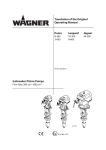
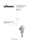
Original Service Manual
Version 02/2015
Airless manual gun
B_5040
VERSION 02/2015
ORDER NUMBER DOC2355506
GM 1-350/530
SERVICE MANUAL
Table of Contents
1
1.1
1.2
1.3
1.4
ABOUT THESE INSTRUCTIONS
Preface
Warnings, Notices and Symbols in these Instructions
Languages
Abbreviations
3
3
3
4
4
2
2.1
2.2
2.3
2.4
2.4.1
2.4.2
2.5
2.5.1
2.5.2
2.5.3
2.5.4
REPAIR WORK
General Notices
Repair Staff
Safety Instructions
Replacing the Valve Rod
Disassembling
Assembly
Replacing the Filter Tube
Required Tools and Aids
Required Spare Parts
Safety Instructions
Disassembly/Assembly
5
5
5
6
7
7
8
9
9
9
10
10
3
FUNCTIONAL CHECK AFTER REPAIR
12
4
4.1
4.2
SPARE PARTS
How Can Spare Parts Be Ordered?
Spare Parts List GM 1-350/530
13
13
14
2
VERSION 02/2015
GM 1-350/530
ORDER NUMBER DOC2355506
SERVICE MANUAL
1
ABOUT THESE INSTRUCTIONS
1.1
PREFACE
This service manual contains information on the maintenance and repair of the devices.
This device can be hazardous if it is not operated in accordance with the information
provided in this service manual and the relevant operating manual.
1.2
WARNINGS, NOTICES AND SYMBOLS IN THESE INSTRUCTIONS
Warning instructions in this operating manual highlight particular dangers to users and to
the device and state measures for avoiding the hazard. These warning instructions fall into
the following categories:
DANGER
Danger - immediate risk of danger.
Non-observance will result in death or serious injury.
This notice warns you of a hazard!
Possible consequences of not observing the warning instructions.
The signal word indicates the hazard level.
The measures for preventing the danger and its
consequences.
Warning - possible imminent danger.
Non-observance may result in death or serious injury.
WARNING
This notice warns you of a hazard!
Possible consequences of not observing the warning instructions.
The signal word indicates the hazard level.
The measures for preventing the danger and its
consequences.
Caution - a possibly hazardous situation.
Non-observance may result in minor injury.
CAUTION
This notice warns you of a hazard!
Possible consequences of not observing the warning instructions.
The signal word indicates the hazard level.
The measures for preventing the danger and its
consequences.
Notice - a possibly hazardous situation.
Non-observance may result in damage to property.
NOTICE
This notice warns you of a hazard!
Possible consequences of not observing the warning instructions. The signal word
indicates the hazard level.
The measures for preventing the danger and its consequences.
Note - provides information about particular characteristics and how to proceed.
3
VERSION 02/2015
ORDER NUMBER DOC2355506
GM 1-350/530
SERVICE MANUAL
1.3
LANGUAGES
The service manual is available in the following languages:
Language:
Order No.
Language:
German
2355505
English
The operating manual is available in the following languages:
Language:
Order No.
Language:
German
2348756
English
French
2355489
Italian
Spanish
2355493
Russian
Chinese
2356565
Order No.
2355506
Order No.
2349369
2355491
2356564
Additional languages on request or at:
1.4
ABBREVIATIONS
Order No.
DN
Order number
Spare part
Marking in the spare parts lists
Position
Number of pieces
Wrench size
Manual gun (gun, manual)
Nominal diameter
4
VERSION 02/2015
ORDER NUMBER DOC2355506
GM 1-350/530
SERVICE MANUAL
2
REPAIR WORK
2.1
GENERAL NOTICES
The following points must be noted for every repair carried out on the device:
• Observe the safety instructions in Chapter 4 of the associated operating manual (see
Chapter 1).
• Decommissioning and cleaning as in Chapter 8.1.3 of the operating manual.
• Loosening of the various connections using the appropriate tools (product hoses and
air hoses).
• Defective product hoses may not be repaired, but must instead be replaced as a complete
part for safety reasons.
• After assembly, the repaired components and complete system must be checked in
accordance with Chapter 3.
2.2
REPAIR STAFF
Repair work must be carried out carefully by qualified and trained staff. They should be
informed of specific hazards during their training.
The following hazards may arise during repair work:
- Health hazard from inhaling solvent vapors
- Use of unsuitable tools and aids
A skilled person must ensure that the device is checked for being in a reliable state after
repair work is completed.
5
VERSION 02/2015
ORDER NUMBER DOC2355506
GM 1-350/530
SERVICE MANUAL
2.3
SAFETY INSTRUCTIONS
Observe the safety instructions in Chapter 4 and in Chapter 8.1.2 of the corresponding
operating manual.
Before repair work
- Flush and clean the system.
Chapter 8.1.3 in the operating manual.
After repair work
- Carry out safety checks in accordance with Chapter 8.2.3. of the operating manual.
- Commission the system and check for leaks as described in Chapter 6.8 of the
operating manual.
- Function test in accordance with Chapter 3.
In accordance with the guideline for liquid ejection devices (ZH 1/406 and BGR 500
Part 2 Chapter 2.29 and Chapter 2.36):
- The liquid ejection devices should be checked by an expert (e.g. Wagner service
technician) for their safe working conditions as required and at least every
12 months.
- For shut down devices, the examination can be suspended until the next start-up.
DANGER
Incorrect maintenance/repair!
Danger to life and equipment damage.
Only a WAGNER service center or a suitably trained person may
carry out repairs and replace parts.
Only repair and replace parts that are listed in the Chapter
"Spare parts" and that are assigned to the unit.
Before all work on the device and in the event of work
interruptions:
- Switch off the energy and compressed air supply.
- Relieve the pressure from the spray gun and device.
- Secure the spray gun against actuation.
Observe the operating manual and service manuals at all times
when carrying out work.
6
VERSION 02/2015
GM 1-350/530
ORDER NUMBER DOC2355506
SERVICE MANUAL
2.4 REPLACING THE VALVE ROD
2.4.1 DISASSEMBLING
1. Flush and clean the spray gun as described in Chapter 8.1.3.
2. Relieve the pressure on the spray gun and product pressure generator in
accordance with Chapter 7.3.2.
3. Secure the spray gun with the locking device.
4. Unscrew preload nut (A) using open-end wrench (wrench size 30 mm; 1.18 inches)
and remove pressure springs (B).
5. The valve rod (D) is unscrewed on the pressure plate (C) using wrench size 10.
Attention: when unscrewing, ensure that the pressure plate is pushed fully onto the
valve rod.
6. Carefully remove the pressure plate (C) and valve rod (D) from the gun housing,
replace the valve rod (D).
Note:
The valve rod can only be ordered as a module; individual valve rod parts are not
available.
A
B
C
D
B_5050
7
VERSION 02/2015
GM 1-350/530
ORDER NUMBER DOC2355506
SERVICE MANUAL
2.4.2
ASSEMBLY
1.
The valve rod (D) is screwed into the gun housing using the pressure plate (C). Here,
ensure that the pressure plate with the recess is pushed completely onto the valve
rod's wrench size (drive coupler) in order to transfer the torque (see Detail 1).
2.
Using a wrench size 6 on the pressure plate (C), screw the pressure plate and valve
rod (D) into the gun housing, tightening torque 6 Nm ± 1 Nm; 4.43 lbft.
3.
Insert the pressure spring (B) and tighten the preload nut (A).
4.
Adjust the valve rod (D) using the Allen wrench (size 3) so that no actuation occurs
in the secured position. Opening stroke 1.2 ± 0.1 mm.
NOTICE
Unsuitable tool!
Damage to seals and sealing surfaces
Do not hold the valve rod with pliers or a similar tool.
A
B
3 Nm; 2.2 lbft
C
D
1
1
1
Drive coupler
B_5053
Drive coupler
C
Wrench
size SW 3
D
B_5052
B_5309
8
VERSION 02/2015
ORDER NUMBER DOC2355506
GM 1-350/530
SERVICE MANUAL
2.5
REPLACING THE FILTER TUBE
2.5.1
REQUIRED TOOLS AND AIDS
The following tools and aids are required for carrying out the repair work on the spray
gun described below:
Description
- Allen wrench SW 6
- Hot-air gun
- Suitable oven for curing the adhesive
2.5.2
REQUIRED SPARE PARTS
The following spare parts are required for carrying out the repair work on the spray gun
described below:
Description
- Filter socket with seal
- Loctite 648
Order No.
2353611
9992804
9
VERSION 02/2015
ORDER NUMBER DOC2355506
GM 1-350/530
SERVICE MANUAL
2.5.3
SAFETY INSTRUCTIONS
WARNING
Incompatibility of cleaning agent and working medium!
Risk of explosion and danger of poisoning by toxic gases
Examine the compatibility of the cleaning agents and working
media on the basis of the safety data sheets.
2.5.4
DISASSEMBLY/ASSEMBLY
Disassembly:
1. Flush and clean the spray gun as described in Chapter 8.1.3 of the operating
manual.
2. Relieve the pressure on the spray gun and product pressure generator in
accordance with Chapter 7.3.2 of the operating manual.
3. Secure the spray gun with the locking device.
4. Use the guard bracket (B) with integrated hex tool to loosen and unscrew the filter
housing (A) (counterclockwise).
5. Remove the filter insert (C) from the filter housing (A).
6. Remove gun handle (D).
7. The filter socket (E) is secured with Loctite 648. Heat the area around the filter
socket to approx. 150 °C; 302 °F.
8. Remove the filter socket (E) using an Allen wrench (size 6).
9. Remove and replace the seal of the filter socket (F).
10. Thoroughly clean all parts with flushing agent.
Assembly:
11. Screw the filter socket (E) with the new seal (F) back into the gun housing and
secure the screw connection with Loctite 648. Place the spray gun into a suitable
oven to cure the adhesive (max. 70 °C; 158 °F).
12. Reassemble the spray gun in reverse order.
Note:
The filter socket seal (F) becomes unusable by heating. When replacing the filter socket,
also replace the seal.
10
VERSION 02/2015
ORDER NUMBER DOC2355506
GM 1-350/530
SERVICE MANUAL
SW6
F
16 Nm ; 11.8 lbft
Loctite 648
E
D
C
A
B
B_5055
11
VERSION 02/2015
ORDER NUMBER DOC2355506
GM 1-350/530
SERVICE MANUAL
3
FUNCTIONAL CHECK AFTER REPAIR
After all repairs, the gun must be checked for safe condition before recommissioning. The
necessary scope of inspection and testing depends on the repair carried out and must be
documented by the repair staff.
Injection and final inspection
Activities
1. Trigger lever function test
- The trigger lever must be pulled as far as it will go.
Make sure that the trigger lever can move slightly in its rest position.
- Put the trigger lever locking device into locking position, configure
product pressure and pull the trigger lever.
(Beware of the the recoil; ensure firm footing and hold gun tight)
No product may not leak out or escape.
- Check that the trigger lever locking device is not reset by the trigger
lever when pulling in the locking position.
2. Leak test
- Connect the spray gun and gradually increase the pressure until the
maximum pressure specified on the type plate has been reached.
- Trigger and flush the spray gun multiple times.
- Make sure that:
The product connection is sealed when the spray gun is closed.
The product valve is sealed.
Product does not discharge at the valve rod seal.
Aid tools
Manual inspection
Visual inspection
350 bar or 530 bar product
connection
3. Flush the spray gun
- Stop the material supply, open the flushing valve, pull the trigger
lever, and flush the spray gun or blow it out with air.
Flush the spray gun without nozzle.
- Close the flushing valve. When almost no material is escaping any
longer, remove the product connection hose and blow the rest of the
test medium out of the spray gun using an air gun.
12
VERSION 02/2015
ORDER NUMBER DOC2355506
GM 1-350/530
SERVICE MANUAL
4
SPARE PARTS
4.1
HOW CAN SPARE PARTS BE ORDERED?
Always supply the following information to ensure delivery of the right spare part:
Order number, designation and quantity
The quantity need not be the same as the number given in the quantity column " "
on the list. This number merely indicates how many of the respective parts are used in
each component.
The following information is also required to ensure smooth processing of your order:
- Address for the invoice
- Address for delivery
- Name of the person to be contacted in the event of any queries
- Type of delivery (normal mail, express delivery, air freight, courier, etc.)
Identification in spare parts lists.
Explanation of column "K" (labeling) in the following spare parts lists:
Wearing parts
Note: These parts are not covered by warranty terms.
Not part of standard equipment, available, however, as additional extra.
DANGER
Incorrect maintenance/repair!
Danger to life and equipment damage.
Only a WAGNER service center or a suitably trained person may
carry out repairs and replace parts.
Only repair and replace parts that are listed in the Chapter
"Spare parts" and that are assigned to the unit.
Before all work on the device and in the event of work
interruptions:
- Switch off the energy and compressed air supply.
- Relieve the pressure from the spray gun and device.
- Secure the spray gun against actuation.
Observe the operating manual and service manuals at all times
when carrying out work.
13
VERSION 02/2015
GM 1-350/530
ORDER NUMBER DOC2355506
SERVICE MANUAL
4.2
SPARE PARTS LIST GM 1-350/530
6
3 Nm;
2.2 lbft
5
1
7
13
6
12
9
70 Nm;
51.6 lbft
8
18
16
10
9
17
16 Nm ;
11.8 lbft
11
19
4
4
2
15
14
3
B_5046
14
VERSION 02/2015
ORDER NUMBER DOC2355506
GM 1-350/530
SERVICE MANUAL
Spare parts list GM 1
1
2
3
4
4
5
6
6
7
8
9
10
11
12
13
14
15
35 MPa
Order No.
2347536
2346614
2353559
2353600
347335
2353607
2353556
2353546
9910403
2343085
2353611
2353613
43411
364340
2315723
2315724
2315725
2315726
2353548
2353549
9992590
9992804
2353551
53 MPa
Order No.
2346856
2346614
2353559
2353599
347335
2353606
2353556
2353546
9910403
2343085
2353611
2353613
43411
364340
2315723
2315724
2315725
2315726
2353548
2353549
9992590
9992804
2353551
Designation
1
GM1
1
Handle
1
Filter housing with guard bracket
1
Trigger guard 4F, complete
1
Trigger guard 2F, complete
1
Pressure spring
1
Preload nut, 530 bar
1
Preload nut, 350 bar
1
Valve rod unit
1
Intermediate piece "G" 7/8-14-UNF
2
Cap nut
1
Bolt
1
Filter socket with seal
1
Spray gun body
2
Actuating pins
1
Seal, filter
1
Filter insert, yellow (middle), 100 mesh per inch *
1
* Filter insert, red (fine), 200 mesh per inch – 10 pieces
1
* Filter insert, blue (middle), 150 mesh per inch – 10 pieces
1
* Filter insert, yellow (middle), 100 mesh per inch – 10 pieces
1
* Filter insert, white (coarse), 50 mesh per inch – 10 pieces
16
1
Seal kit PT-HD GM1 – 5 pieces
17
1
Nozzle holder PT-HD GM1
18
1
Loctite 222
19
1
Loctite 648
1
Service set GM1
20
Wearing parts
= Included in service set
Not part of the standard equipment, but available as a special accessory
15
ED
FI
CERT
I
Order No.
Edition
2355506
02/2015
Germany
Phone
Telefax
E-mail
Switzerland
Document No. 11170009
Version -
Phone
Telefax
More contact addresses on the internet at:
Company/Locations/WAGNER worldwide
Subject to changes without notice