1
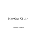
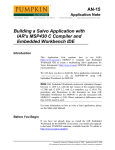
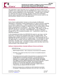
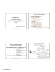
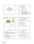
Texas Instruments MSP-FET430P140 Flash Emulation Tool
User’s Guide
Introduction
Thank you for purchasing a Texas Instruments MSP-FET430P140 Flash Emulation Tool for our
MSP430F13x/14x ultra-low power microcontroller.
This tool contains the most up-to-date materials available at the time of packaging. For the latest materials
(data sheets, software, applications, etc.), please visit our MSP430 web site at www.ti.com/sc/msp430, or
contact your local TI sales office.
This document supplements the existing TI and IAR documentation. This document does not fully teach
the MSP430 or the IAR systems. For details of these systems, please refer to the appropriate TI and IAR
documents listed in “Sources of Additional Information” within the Appendices.
Get Started Now!
Kit Contents
1.
One Product Disclaimer document.
2.
One READ ME FIRST document.
3.
One MSP430 CD-ROM.
4.
One MSP-FETP430IF FET Interface module. This is the unit that has a 25-pin male D-Sub connector
on one end of the case, and a 2x7 pin male connector on the other end of the case.
5.
One MSP-TS430PM64 Target Socket module. This is the PCB on which is mounted a clam-shell-style
socket for the MSP430F149. A 2x7 pin male connector is also present on the PCB.
6.
One 25-conductor cable.
7.
One 14-conductor cable.
8.
Eight PCB 2x7 pin connectors (Four male and four female).
9.
One small, black box containing two PMS430F149PM devices. PMS devices are preliminary devices.
Please consult the data sheet for device specifications. A list of device errata can be found at
http://www.ti.com/sc/cgi-bin/buglist.cgi
Version 2.02
1/30
08/31/00
MSP-FET430P140 Flash Emulation Tool User’s Guide
Software Installation
1.
Follow the instructions on the supplied READ ME FIRST document to install the IAR Workbench
(assembler and C project development environment) and IAR C-SPY (assembler and C debugger).
Please read the file ew430ks.htm for the latest information about the Workbench, and read the file
cw430.pdf for the latest information about C-SPY. For simplicity, the term KickStart is used to refer to
the development environment that consists of the Workbench and C-SPY.
KickStart is compatible with WINDOWS ’95, ’98, and NT4.0.
Significant Changes from Software Version 2.00
1.
Numerous bugs in the C-SPY/FET driver have been corrected. The performance and robustness of the
driver has been greatly improved.
2.
FLASH memory is always checked for erasure prior to programming, and correct FLASH
programming is always verified. The C-SPY options that previously enabled and disabled these
operations have been removed.
3.
Numerous bugs in KickStart (assembler, compiler, etc.) have been corrected.
4.
The KickStart support file (*.h, *.xcl, *.ddf) structure has been changed. Previously, generic support
files were provided that supported the MSP430 device present at that time. With the introduction of the
FLASH devices (F110, F1101, F112, F1121, F133, F135, F147, F148, F149) these generic support
files became too complex and unmanageable. A decision was made to provide .xcl and .ddf files for
each MSP430 device, and .h files for each device family (11x, 11x1, 13x, 14x, 31x, 32x, 33x). The
generic support files are no longer provided. Consequently, programs and projects that make use of
these generic support files will have to be reworked to make use of these new device-specific support
files. The required modifications should be miniscule (change the file #included, and change the linker
and C-SPY project settings).
Hardware Installation
1.
Use the 25-conductor cable to connect the FET Interface module to the parallel port of your PC.
2.
Use the 14-conductor cable to connect the FET Interface module to the Target Socket module.
3.
Ensure that the MSP430F149 is securely seated in the socket, and that its pin 1 (indicated with a
circular indentation on the top surface) aligns with the “1” mark on the PCB.
4.
Ensure that jumpers JP1 and JP2 (near the 2x7 pin male connector) are in place. A picture of the Target
Socket module and its parts is presented later in this document.
Important MSP430 Documents on the CD-ROM
The MSP430 CD-ROM supplied with the FET contains a wealth of information.
From the MSP430 main page on the CD-ROM, Literature->MSP430 Literature->Data Sheets presents the
MSP430 device data sheets.
From the MSP430 main page on the CD-ROM, Literature->MSP430 Literature->User’s Guides” presents
User’s Guides for our suite of MSP430 tools.
Version 2.02
2/30
08/31/00
MSP-FET430P140 Flash Emulation Tool User’s Guide
“FLASH”ing the LED (an example in assembler and C)
This section demonstrates on the FET the equivalent of the C-language “Hello, world!”; assembler and C
applications that flash the LED are developed and downloaded to the FET, and then run.
Assembler Example
1.
Start the Workbench (START->PROGRAMS->IAR SYSTEMS->IAR EMBEDDED WORKBENCH
FOR MSP430 KICKSTART->IAR EMBEDDED WORKBENCH).
2.
Use FILE->OPEN to open the project file at:
430->FET_examples->F149->Assembler->Fet_1->Fet_1.prj
3.
Use PROJECT->BUILD ALL to assemble and link the source code. You can view the source code by
double-clicking Common Sources, and then double-clicking on the file Fet_1.s43 in the Fet_1.prj
window.
4.
Ensure that C-SPY is properly configured (With DEBUG selected, PROJECT->OPTIONS, C-SPY);
1. SETUP, DRIVER, Flash Emulation Tool
2. SETUP, CHIP DESCRIPTION, $TOOLKIT_DIR$\cw430\msp430F149.ddf
3. PARALLEL PORT, PARALLEL PORT, LPT1 or LPT2 or LPT3
5.
Use PROJECT->DEBUGGER to start C-SPY. C-SPY will erase the device FLASH, and then
download to the device FLASH the application object file.
6.
In C-SPY, use EXECUTE->GO to start the application. The LED should flash!
7.
In C-SPY, use FILE-EXIT to exit C-SPY.
8.
In the Workbench, use FILE-EXIT to exit the Workbench.
Congratulations, you’ve just developed and tested your first MSP430F149 assembler application!
C Example
1.
Start the Workbench (START->PROGRAMS->IAR SYSTEMS->IAR EMBEDDED WORKBENCH
FOR MSP430 KICKSTART->IAR EMBEDDED WORKBENCH).
2.
Use FILE->OPEN to open the project file at: 430->FET_examples->F149->C->Fet_1->Fet_1.prj
3.
Use PROJECT->BUILD ALL to compile and link the source code. You can view the source code by
double-clicking Common Sources, and then double-clicking on the file Fet_1.c in the Fet_1.prj
window.
4.
Ensure that C-SPY is properly configured (With DEBUG selected, PROJECT->OPTIONS, C-SPY);
1. SETUP, DRIVER, Flash Emulation Tool
2. SETUP, CHIP DESCRIPTION, $TOOLKIT_DIR$\cw430\msp430F149.ddf
3. PARALLEL PORT, PARALLEL PORT, LPT1 or LPT2 or LPT3
5.
Use PROJECT->DEBUGGER to start C-SPY. C-SPY will erase the device FLASH, and then
download to the device FLASH the application object file.
6.
In C-SPY, use EXECUTE->GO to start the application. The LED should flash!
7.
In C-SPY, use FILE-EXIT to exit C-SPY.
8.
In the Workbench, use FILE-EXIT to exit the Workbench.
Congratulations, you’ve just developed and tested your first MSP430F149 “C” application!
Version 2.02
3/30
08/31/00
MSP-FET430P140 Flash Emulation Tool User’s Guide
Development Flow
Overview
Applications are developed in assembler and/or C using the Workbench, and they are debugged using CSPY. C-SPY can be configured to operate with the FET (i.e., an actual MSP430F149), or with a software
simulation of the device.
Documentation for the MSP430 family and KickStart is extensive. The CD-ROM supplied with this tool
contains a large amount of documentation describing the MSP430. The MSP430 home page on the world
wide web (www.ti.com/sc/msp430) is another source of MSP430 information. The components of
KickStart (assembler, compiler, workbench, debugger) are fully documented in 430\doc under the
KickStart installation directory root (see readme.htm). Additional files located throughout the KickStart
directory tree contain the most up to date information and supplement the .pdf files. In addition, KickStart
documentation is available on-line via HELP. Please ignore the references in the KickStart documentation
to DOS and “Command Line” commands. The IAR User’s Guides (.pdf) do not make reference to the FET
or the MSP430F13x/14x devices.
430\doc\FET_Doc_Overview.htm conveniently organizes the IAR and TI documents.
Tool
User’s Guide
Most Up To Date Information
Workbench
ew430.pdf
ew430ks.htm
Assembler
a430.pdf
a430.htm
Compiler
icc430.pdf
icc430.htm
C library
clib.txt
Linker
Xlink.txt
Linker
Xman.txt
C-SPY Debugger
cw430.pdf
cw430.pdf
Using KickStart
The KickStart development environment is limited. The following restrictions are in place:
1.
The C compiler supports a maximum of 1kb generated code and has no support for floating-point
arithmetic. It will not generate any assembly code output. The assembler is not restricted.
2.
The linker will link a maximum of 1kb originating from C source code, but an unlimited amount of
code originating from assembler source.
3.
C-SPY does not support code profiling.
A “full” (i.e., unrestricted) version of the software tools can be purchased from IAR. A “mid-featured” tool
set – called Baseline, with a 4K code size limitation – is also available. Please consult the IAR web site
(www.iar.se) for more information. FET drivers for these software tools are available.
Unlike the full version of the IAR tools, KickStart does not require a security “dongle” to operate.
Version 2.02
4/30
08/31/00
MSP-FET430P140 Flash Emulation Tool User’s Guide
Project Settings
The settings required to configure the Workbench and C-SPY are numerous and detailed. Please read and
understand the supplied KickStart documentation thoroughly when dealing with project settings. Please
review the project files (.prj) supplied with the assembler and C examples; use these files as templates
when developing your own project files. The project options are accessed using: PROJECT->OPTIONS
Some noteworthy items are:
1.
Choose the –v1 330 Processor Configuration with support for hardware multiply when developing
with the MSP430F14x. Choose the –v0 310/320 Processor Configuration without support for hardware
multiply when developing with the MSP430F13x. (GENERAL, TARGET)
2.
Enable Debug Information in the compiler. (ICC430, DEBUG)
3.
Enable Generate Debug Information in the assembler. (A430, CODE GENERATION)
4.
Enable Debug Info in the linker Format section. (XLINK, OUTPUT)
5.
Override the XCL File Name. See System Files below. (XLINK, INCLUDE)
6.
Select the C-SPY driver: Select Simulator to debug on the simulator. Select Flash Emulation Tool to
debug on the FET. (C-SPY, SETUP). Select the active parallel port in PARALLEL PORT.
7.
Override and select the correct Chip Description for C-SPY. See System Files below. (C-SPY,
SETUP)
System Files
The following configuration and special files are provided to facilitate development of MSP430
applications under KickStart/MSP-FET430P140. In each category, choose the file corresponding to the
specific device being developed for.
1.
Linker control files for point 5. above that support assembler development:
$TOOLKIT_DIR$\icc430\msp430F133A.xcl
$TOOLKIT_DIR$\icc430\msp430F135A.xcl
$TOOLKIT_DIR$\icc430\msp430F147A.xcl
$TOOLKIT_DIR$\icc430\msp430F148A.xcl
$TOOLKIT_DIR$\icc430\msp430F149A.xcl
2.
Linker control files for point 5. above that support C development:
$TOOLKIT_DIR$\icc430\msp430F133C.xcl
$TOOLKIT_DIR$\icc430\msp430F135C.xcl
$TOOLKIT_DIR$\icc430\msp430F147C.xcl
$TOOLKIT_DIR$\icc430\msp430F148C.xcl
$TOOLKIT_DIR$\icc430\msp430F149C.xcl
3.
Chip Description files for point 7. above that support debugging:
$TOOLKIT_DIR$\cw430\msp430F133.ddf
$TOOLKIT_DIR$\cw430\msp430F135.ddf
$TOOLKIT_DIR$\cw430\msp430F147.ddf
$TOOLKIT_DIR$\cw430\msp430F148.ddf
$TOOLKIT_DIR$\cw430\msp430F149.ddf
4.
Device definition “#include” files:
$TOOLKIT_DIR$\inc\msp430x13x.h
$TOOLKIT_DIR$\inc\msp430x14x.h
5.
C library files:
$TOOLKIT_DIR$\lib\cl430ks.r43
$TOOLKIT_DIR$\lib\cl430ksm.r43
// For MSP430F13x (without hardware multiplier)
// For MSP430F14x (with hardware multiplier)
System files are also provided for all other MSP430 devices.
Version 2.02
5/30
08/31/00
MSP-FET430P140 Flash Emulation Tool User’s Guide
Realtime/Non-Realtime Debugging
C-SPY supports two fundamental modes of debugging: Realtime and Non-Realtime. During Realtime
debugging, the device operates at full device speed and makes use of a limited number of on-chip
debugging resources (specifically, three address breakpoint registers). During Non-Realtime debugging, the
device executes under the control of the host PC; the system operates at a much slower speed, but offers a
software breakpoint at every instruction address. During Non-Realtime mode, the PC effectively repeatedly
single steps the device and interrogates the program counter after each operation. Realtime is the default
mode. CONTROL->REALTIME selects or deselects Realtime mode.
Attention: When Realtime is selected, (single) STEP is disabled and GO can only be executed with a
maximum of three breakpoints active. If more than three breakpoints are active in Realtime mode and GO
is selected, a message is output that informs the user that the operation is not possible.
Using Breakpoints
If there are three or fewer breakpoints active, C-SPY will always operate in Realtime mode (regardless of
the setting of CONTROL->REALTIME).
If there are four or more breakpoints active, C-SPY will only operate in Non-Realtime mode (regardless of
the setting of CONTROL->REALTIME).
The GO TO CURSOR operation implicitly requires a breakpoint.
RESET’ing a C program implicitly requires a breakpoint.
If, during a breakpoint, an interrupt becomes pending, the current instruction is completed and the first
instruction of the interrupt service routine becomes the next instruction (i.e,. C-SPY breaks at the start of
the interrupt service routine).
Note: Only address breakpoints on instruction fetches are supported; data breakpoints are not yet supported.
Using Single Step
Non-Realtime mode must be selected to enable single stepping.
A single step operation within an assembler file executes the next assembler instruction. Thus, it is not
possible to step over a CALL (i.e., a single step within an assembler file operates as a STEP INTO). The
instruction executes at full device speed. A true Step (i.e, stepping around a function CALL) can be
synthesized in assembler files by placing a breakpoint after the CALL and GO’ing (to the breakpoint).
A single step operation within a C file executes the next C statement. Thus, it is possible to step over a
function reference. Statements are executed in Non-Realtime mode. STEP INTO is supported.
It is only possible to single step when source statements are present. Breakpoints must be used when
running code for which there is no source code (i.e., place the breakpoint after the CALL to the function for
which there is no source, and then GO to the breakpoint [in Realtime mode]).
If, during a single step operation, an interrupt becomes pending, the current instruction is completed and the
first instruction of the interrupt service routine becomes the next instruction (i.e,. C-SPY steps to the start
of the interrupt service routine).
Version 2.02
6/30
08/31/00
MSP-FET430P140 Flash Emulation Tool User’s Guide
FET Specific Menus
Control->Real Time
Select Realtime mode or deselect Realtime mode (i.e., Non-Realtime mode).
FET Options->Download Options
•
Erase Flash Memory before Download
•
Main and Information Memory
Erase both FLASH memories before download.
•
Main Memory only
Erase the Main FLASH memory only before download. The Information memory is not
erased.
•
Retain Unchanged Memory
The Information and Main FLASH memories are read into a buffer. The FLASH
memories are then erased. The data to be written is written to the buffer (overwriting the
previous buffer contents at those selected locations). The new data effectively replaces
the old data, and unaffected old data is retained. The buffer is then written to the FLASH
memories.
FET Options->Release JTAG on Go
This option has no effect.
FET Options->Resynchronize JTAG
Regain control of the device.
FET Options->Init New Device
Initialize the device according to the settings in the Download Options. Basically, the current program file
is downloaded to the device memory. The device is then reset. This option can be used to program multiple
devices with the same program from within the same C-SPY session.
Version 2.02
7/30
08/31/00
MSP-FET430P140 Flash Emulation Tool User’s Guide
Appendices
Sources of Additional Information
The primary sources of MSP430 device information include the following TI documents: the Architecture
Guide, the Software User’s Guide (TI), tool manuals, and the specific device datasheet. The most up to date
versions of these documents available at the time of production have been provided on the CD-ROM
included with this tool. The MSP430 web site (www.ti.com/sc/msp430) will contain the latest version of
these documents.
The .pdf files in the 430\doc directory document KickStart. A copy of the .pdf file are include on the
MSP430 CD-ROM. The IAR User’s Guides (.pdf) do not make reference to the FET or the
MSP430F13x/14x devices.
Sources of Assistance
Support for the MSP430 device and the FET is provided by the Texas Instruments Product Information
Group (PIC). Contact information for the PIC can be found on the TI web site at www.ti.com. Additional
device-specific information can be found on the MSP430 web site at www.ti.com/sc/msp430.
Note: Although KickStart is a product of IAR, Texas Instruments provides the support for it. Therefore,
please do not request support for KickStart from IAR. Please consult the extensive documentation provided
with the product before requesting assistance.
Design Considerations for In-Circuit Programming
Boot Strap Loader
The JTAG pins provide access to the FLASH memory of the current MSP430F13x/14x device. In addition,
future versions of MSP430 FLASH devices will contain a program (a “Boot Strap Loader”) that permits the
FLASH memory to be erased and programmed simply. Only port pins P1.1 and P2.2 are required to
support this functionality. An Application Note that fully describes this interface is being developed. Texas
Instruments suggests that customers of the MSP430 FLASH devices design their circuits with this
capability in mind (i.e., we suggest that the customer provide easy access to these two pins (say, via a
header)).
How to generate Texas Instrument .TXT (and other format) files
The KickStart linker can be configured to output objects in TI .TXT format. Select OTHER in the
FORMAT section of the OUPUT tab of the XLINK option, and scroll to select msp430-txt. Intel and
Motorola formats can also be selected.
Note: At this time C-SPY cannot input a .TXT file.
Version 2.02
8/30
08/31/00
MSP-FET430P140 Flash Emulation Tool User’s Guide
Miscellaneous
1.
The state of the machine (registers, memory, etc.) is undefined following a reset, or (re)programming
of the FLASH. The only exception to the above statement is that the PC is loaded with the word at
0xfffe (i.e., the reset vector).
2.
The break-on-data capability of the MSP430F13x/14x is not utilized. At this time, breakpoints can
only be set to occur during an instruction fetch. Future versions of C-SPY may provide this additional
functionality.
3.
A common MSP430 “mistake” is to fail to disable the Watchdog mechanism; the Watchdog is enabled
by default, and it will reset the device if not disabled or properly handled by your application.
4.
C-SPY is capable of downloading data into RAM, INFORMATION, and FLASH MAIN memories.
5.
C-SPY is incapable of downloading data that originates from a full-featured IAR system.
6.
C-SPY is capable of debugging applications that utilize interrupts and low power modes. It is not
possible to single step beyond an instruction that enables a low power mode as the instruction
effectively turns off the device. The user is warned if such an operation is attempted.
7.
C-SPY is incapable of accessing the device registers and memory while the device is running. The user
is warned if such an operation is attempted. The user must stop the device in order to access device
registers and memory.
8.
When C-SPY is started, the FLASH memory is erased and the opened file programmed in accordance
with the previous Download Options. This initial erase and program operation can be disabled from
within the Workbench by selecting PROJECT->OPTIONS, C-SPY, EMULATOR, CODE, Suppress
Load. Programming of the FLASH can be initiated manually with FET OPTIONS->INIT NEW
DEVICE.
9.
The parallel port designators (LPTx) have the following physical addresses: LPT1: 378h, LPT2: 278h,
LPT3: 3BCh.
10. When adding source files to a project, do not add files that are #include’ed by source files that have
already been added to the project (say, an .h file within a .c or .S43 file). These files will be added to
the project file hierarchy automatically.
11. In assembler, enclosing a string in double-quotes (“string”) automatically prepends a zero byte to the
string. Enclosing a string in single-quotes (‘string’) does not.
12. When using the compiler or the assembler, if the last character of a source line is backslash (\), the
subsequent carriage return/line feed is ignored (i.e., it is as if the current line and the next line are a
single line). When used in this way, the backslash character is a “Line Continuation” character.
13. The 14-conductor cable connecting the MSP-FETP430IF and the MSP-TS430PM64 must not exceed 8
inches (20 centimeters) in length.
14. To utilize the on-chip ADC voltage reference, C6 (10uF, 6.3V, low leakage) must be installed on the
MSP-TS430PM64.
15. Crystals/resonators Q1 and Q2 are not provided on the MSP-TS430PM64.
Overview of Example Programs
Example programs for the FET are provided in 430\FET_examples\F149. Both assembler and C examples
are provided in their respective sub-directories. 430\FET_examples\Content.txt describes each of the
example programs.
430\FET_examples\F1121 contains many assembler and C example programs for the MSP430F1121.
These programs can be easily modified to work with the MSP430F149. Note that the MSP-TS430PM64
does not provide a 32KHz crystal; many of the MSP430F1121 examples assume the presence of such a
crystal.
Version 2.02
9/30
08/31/00
MSP-FET430P140 Flash Emulation Tool User’s Guide
Known Problems
1.
When debugging in C with three or more breakpoints active and in Realtime mode, a RESET
causes the source window to go blank. A breakpoint is implicitly required following the RESET of a
C program; the breakpoint is used to halt on main(). If zero or one or two breakpoints are active when
RESET is asserted, there is no problem (since one or two or three breakpoints total are needed) and the
application executes in Realtime mode to main(). However, following a RESET when three or more
breakpoints are active, the debugger enters Non-Realtime mode (since four or more breakpoints are
needed). In Non-Realtime mode, the debugger will execute the single instruction at the first line of the
C set-up routine cstartup.s43. And since there is no source file for this routine in the project, a blank
screen is displayed. If the system is set to display mixed C and assembler (VIEW->TOGGLE
SOURCE/DISASSEMBLY), the assembler statements can be viewed. If the debugger was in NonRealtime mode when the RESET was asserted, the CPU will automatically single step until it
eventually reaches main(). At this time the source window will be refreshed with the cursor positioned
on the first statement of main().
2.
Note: The CONTROL->FILL MEMORY utility of C-SPY requires hexadecimal values for starting
address and length to be prefaced with “0x”. Otherwise the values are interpreted as decimal.
3.
The MEMORY utility of C-SPY can be used to view the RAM, the INFORMATION memory, and the
FLASH MAIN memory. The MEMORY utility of C-SPY can be used to modify the RAM; the
INFORMATION memory and FLASH MAIN memory cannot be modified using the MEMORY
utility. The INFORMATION memory and FLASH MAIN memory can only be programmed when a
project is opened and the data is downloaded to the device, or when FET OPTIONS->INIT NEW
DEVICE is selected.
4.
The GO TO CURSOR operation implicitly requires one breakpoint. Therefore, only one or two
additional breakpoints can be supported while in Realtime mode when this feature is used. However,
C-SPY will permit any number of breakpoints to be set, and it will indicate that the GO TO CURSOR
function is available for use. C-SPY will output an error message indicating that too many breakpoints
are set (either explicitly or implicitly) if program execution is then attempted.
5.
C-SPY does not permit the individual segments of the INFORMATION memory and the FLASH
MAIN memory to be manipulated separately; consider the INFORMATION memory to be one
contiguous memory, and the FLASH MAIN memory to be a second contiguous memory.
6.
The MEMORY window correctly displays the contents of memory where it is present. However, the
MEMORY window incorrectly displays the contents of memory where there is none present.
Memory should only be used in the address ranges as specified by the device data sheet.
7.
Do not use C-SPY to single-step instructions that program the FLASH memory; the time delays
that C-SPY and the user introduce during the programming process may destroy the FLASH memory.
Use Realtime mode to ensure that the FLASH is programmed at full CPU speed.
8.
C-SPY utilizes the system clock to control the device during debugging. Therefore, device counters,
etc., that are clocked by the system clock (SMCLK, MCLK) will be effected when C-SPY has
control over the device. Special precautions are taken to minimize the effect upon the Watchdog
Timer. The CPU core registers are preserved. All other clock sources and peripherals continue to
operate during emulation. In other words, the Flash Emulation Tool is a partially intrusive tool.
9.
The Workbench is capable of producing an object file in Texas Instruments .TXT format. C-SPY is
incapable of inputting an object file in Texas Instruments .TXT format. A utility program will
soon be made available that programs the device memory with a .TXT file.
10. The example programs giving in the KickStart documentation (i.e., demo, tutor, etc.) are not
correct. The programs will work in the KickStart simulator. However, the programs will not function
correctly on the actual device because the Watchdog mechanism is active. The programs need to be
modified to disable the Watchdog mechanism. Disable the Watchdog mechanism with the C statement:
“WDTCTL = 0x5a80;”, or “mov #5a80h,&WDTCTL” in assembler. Note: Many of the examples
Version 2.02
10/30
08/31/00
MSP-FET430P140 Flash Emulation Tool User’s Guide
assume the LCD version of the MSP430. The FET is provided with an MSP430 device that does not
directly drive an LCD.
11. There is a time after C-SPY performs a hard reset of the device (when the C-SPY session is first
started, when the FLASH is reprogrammed (via Init New Device), when JTAG is resynchronized
(Resynchronize JTAG)) and before C-SPY has regained control of the device that the device will
execute normally. This behavior may have side effects. Once C-SPY has regained control of the
device, it will perform a soft reset of the device and retain control.
12. It is not possible to step beyond a low power mode instruction. While debugging in C, it is
necessary to have a meaningful C statement following the LPM instruction so that C-SPY can
synchronize the returned PC with the C source (else C-SPY will repeatedly single step). Following the
LPM with a _NOP(); works well in this case.
13. GO OUT is not available while debugging assemler files. GO OUT operates like GO while
debugging assembler files.
14. Information Memory may not be blank (erased to 0xff) when the device is delivered from TI.
Customers should erase the Information Memory before its first usage. Main Memory of packaged
devices is blank when the device is delivered from TI.
15. For IBM Thinkpads, change R6 from 330ohms to 100ohms. This change will increase the power
requirements of the FET. If the parallel port is incapable of sourcing this additional current, the user
may supply power from an external source via J4.
16. When C-SPY is invoked, the Tutor (or Demo) project will always be opened. This can be very
annoying (especially considering that C-SPY is capable of opening the last project opened). Edit the
system shortcut to C-SPY and delete the reference to the Tutor (or Demo) project.
17. Within C-SPY, MEMORY->EDIT is used to read and write memory. Be aware that MEMORY>EDIT always operates upon sixteen bytes of memory (xxx0h->xxxfh). These unintended accesses
may have undesirable side effects (especially when working with peripheral registers, etc.).
18. When using the Advanced FLASH Programming sequence to program the FLASH, do not set a
breakpoint on the instruction immediately following the write to FLASH operation. A simple
work-around to this limitation is to follow the write to FLASH operation with a NOP, and set a
breakpoint on the instruction following the NOP.
19. In assembler, “#define string value” should not be followed with an assembler-style (;) comment
(as the comment will become part of “string” [since, by definition of #define, “value” extends to the
end of the current line]). C-style (/*, */) and C++-style (//) comments can be used with #define without
problem.
20. When defining modules, special function definitions (SFRB, SFRW) are cleared from the
assembler/compiler when a new module is started. Consequently, it is required to re-#include the .h
file that contains the SFR definitions. However, to enable this operation one must first circumvent the
prevent-multiple-file-inclusion mechanism by use of the following statement prior to the #include
operation: #undef __msp430xxxx (where xxxx is the device identification). If this operation is not
done, the .h file will not be included, and the SFR definitions will be unknown.
21. The following cryptic error message is output by the linker when a C.xcl file is incorrectly used in
an assembler project:
Error[e46]: Undefined external “main” referred in CSTARTUP
Warning[w52]: More than one definition for the byte at address 0xfffe in common segment INTVEC. It
is defined in module “CSTARTUP” as well as in module “…”
The solution to this problem is to use the correct A.xcl file (for assembler).
Version 2.02
11/30
08/31/00
MSP-FET430P140 Flash Emulation Tool User’s Guide
22. Do not set a breakpoint (either explicitly or implicitly [using GO TO CURSOR]) on the instruction
immediately following an instruction that causes the device to enter a low-power mode. A simply
work-around to this limitation is to follow the low-power mode instruction with NOP (or _NOP();),
and set the breakpoint on the instruction following the NOP.
Version 2.02
12/30
08/31/00
MSP-FET430P140 Flash Emulation Tool User’s Guide
Schematics and PCB Pictorials
Version 2.02
13/30
08/31/00
MSP-FET430P140 Flash Emulation Tool User’s Guide
Version 2.02
14/30
08/31/00
MSP-FET430P140 Flash Emulation Tool User’s Guide
Version 2.02
15/30
08/31/00
MSP-FET430P140 Flash Emulation Tool User’s Guide
Version 2.02
16/30
08/31/00
MSP-FET430P140 Flash Emulation Tool User’s Guide
LED3 connected to P1.0
Jumper JP1
Open to measure current
Jumper JP2
Open to disconnect LED3
Orient Pin 1 of
MSP430F13x/14x
Version 2.02
17/30
08/31/00
MSP-FET430P140 Flash Emulation Tool User’s Guide
TI-to-IAR Assembler Directive Conversion
Texas Instruments makes a suite of development tools for the MSP430, including a comprehensive
assembler and device simulator. The source of the TI assembler and the source of the KickStart assembler
are not 100% compatible; the instruction mnemonics are identical, while the assembler directives are
somewhat different. The following section documents the differences between the TI assembler directives
and the KickStart assembler directives.
Translating Asm430 Assembler Directives to A430 Directives
1 Introduction
The following sections describe, in general, how to convert assembler directives for Texas Instruments’
Asm430 assembler (Asm430) to assembler directives for IAR’s A430 assembler (A430). These sections
are only intended to act as a guide for translation. For detailed descriptions of each directive, refer to either
the MSP430 Assembly Language Tools User’s Guide, SLAUE12, from Texas Instruments, or the MSP430
Assembler User’s Guide from IAR.
Note:
Only the assembler directives require conversion - not the assembler instructions. Both assemblers use the
same instruction mnemonics, operands, operators, and special symbols such as the section program counter
($), and the comment delimiter (;).
The A430 assembler is not case sensitive by default. These sections show the A430 directives written in
uppercase to distinguish them from the Asm430 directives, which are shown in lower case.
2 Character strings
In addition to using different directives, each assembler uses different syntax for character strings. A430
uses C syntax for character strings: A quote is represented using the backslash character as an escape
character together with quote (\”) and the backslash itself is represented by two consecutive backslashes
(\\). In Asm430 syntax, a quote is represented by two consecutive quotes (“”). See examples below:
Character String
PLAN “C”
\dos\command.com
Concatenated string (i.e. Error 41)
Version 2.02
Asm430 Syntax (TI)
“PLAN “”C”””
“\dos\command.com”
-
18/30
A430 Syntax (IAR)
“PLAN \”C\””
“\\dos\\command.com”
“Error ” “41”
08/31/00
MSP-FET430P140 Flash Emulation Tool User’s Guide
3 Section Control Directives
Asm430 has three predefined sections into which various parts of a program are assembled. Uninitialized
data is assembled into the .bss section, initialized data into the .data section and executable code into the
.text section.
A430 also uses sections or segments, but there are no predefined segment names. Often, it is convenient to
adhere to the names used by the C compiler: UDATA0 for uninitialized data, CONST for constant
(initialized) data and CODE for executable code. The table below uses these names.
A pair of segments can be used to make initialized, modifiable data PROM-able. The ROM segment would
contain the initializers and would be copied to RAM segment by a start-up routine. In this case, the
segments must be exactly the same size and layout.
Description
Asm430 Directive (TI)
A430 Directive (IAR)
Reserve size bytes in the .bss
.bss
(1)
(uninitialized data) section
Assemble into the .data (initialized data)
.data
RSEG const
section
Assemble into a named (initialized)
.sect
RSEG
section
Assemble into the .text (executable code)
.text
RSEG code
section
Reserve space in a named (uninitialized)
.usect
(1)
section
Alignment on byte boundary
.align
(2)
Alignment on word boundary
.even
EVEN
(1) Space is reserved in an uninitialized segment by first switching to that segment, then defining the
appropriate memory block, and then switching back to the original segment. For example:
RSEG UDATA0
DS
16
RSEG CODE
(2) Initialization of bit-field constants (.field) is not supported, therefore, the section counter is always
byte-aligned.
LABEL:
Additional A430 Directives (IAR)
Switch to an absolute segment
Switch to a relocatable segment
Switch to a common segment
Switch to a stack segment (high-to-low allocation)
Alignment on specified address boundary (power of two)
Set the location counter
Version 2.02
19/30
A430 Directive (IAR)
ASEG
RSEG
COMMON
STACK
ALIGN
ORG
08/31/00
MSP-FET430P140 Flash Emulation Tool User’s Guide
4 Constant Initialization Directives
Description
Asm430 Directive (TI)
A430 Directive (IAR)
Initialize one or more successive bytes or
.byte or .string
DB
text strings
Initialize a 48-bit MSP430 floating-point
.double
(1)
constant
Initialize a variable-length field
.field
(2)
Initialize a 32-bit MSP430 floating-point
.float
DF (3)
constant
Reserve size bytes in the current section
.space
DS
Initialize one or more text strings
.string
DB
Initialize one or more 16-bit integers
.word
DW
(1) The 48-bit MSP430 format is not supported
(2) Initialization of bit-field constants (.field) is not supported. Constants must be combined into complete
words using DW.
; Asm430 code
; A430 code
.field 5,3
\
.field 12,4
|!
DW (30<<(4+3)) | (12<<3) | 5 ; equals 3941
.field 30,8
/
(3) The 32-bit IEEE floating-point format, used by the C Compiler, is supported in the A430 assembler.
Additional A430 Directives (IAR)
Initialize one or more 32-bit integers
Version 2.02
A430 Directive (IAR)
DL
20/30
08/31/00
MSP-FET430P140 Flash Emulation Tool User’s Guide
5 Listing Control Directives
Description
Allow false conditional code block listing
Inhibit false conditional code block listing
Set the page length of the source listing
Set the page width of the source listing
Restart the source listing
Stop the source listing
Allow macro listings and loop blocks
Asm430 Directive (TI)
.fclist
.fcnolist
.length
.width
.list
.nolist
.mlist
Inhibit macro listings and loop blocks
.mnolist
A430 Directive (IAR)
LSTCNDLSTCND+
PAGSIZ
COL
LSTOUT+
LSTOUTLSTEXP+ (macro)
LSTREP+ (loop blocks)
LSTEXP- (macro)
LSTREP- (loop blocks)
(1)
PAGE
(2)
Select output listing options
.option
Eject a page in the source listing
.page
Allow expanded substitution symbol
.sslist
listing
Inhibit expanded substitution symbol
.ssnolist
(2)
listing
Print a title in the listing page header
.title
(3)
(1) No A430 directive directly corresponds to .option. The individual listing control directives (above) or
the command-line option -c (with suboptions) should be used to replace the .option directive.
(2) There is no directive that directly corresponds to .sslist/.ssnolist.
(3) The title in the listing page header is the source file name.
Additional A430 Directives (IAR)
Allow/inhibit listing of macro definitions
Allow/inhibit multi-line code listing
Allow/inhibit partitioning of listing into pages
Generate cross reference table
Version 2.02
A430 Directive (IAR)
LSTMAC (+/-)
LSTCOD (+/-)
LSTPAG (+/-)
LSTXREF (+/-)
21/30
08/31/00
MSP-FET430P140 Flash Emulation Tool User’s Guide
6 File Referencing Directives
Description
Asm430 Directive (TI)
A430 Directive (IAR)
Include source statements from another
.copy or .include
#include or $
file
Identify one or more symbols that are
.def
PUBLIC or EXPORT
defined in the current module and used in
other modules
Identify one or more global (external)
.global
(1)
symbols
Define a macro library
.mlib
(2)
.ref
EXTERN or IMPORT
Identify one or more symbols that are
used in the current module but defined in
another module
(1) The directive .global functions as either .def if the symbol is defined in the current module, or .ref
otherwise. PUBLIC or EXTERN must be used as applicable with the A430 assembler to replace the
.global directive.
(2) The concept of macro libraries is not supported. Include files with macro definitions must be used for
this functionality.
Modules may be used with the Asm430 assembler to create individually linkable routines. A file may
contain multiple modules or routines. All symbols except those created by DEFINE, #define (IAR
preprocessor directive) or MACRO are “undefined” at module end. Library modules are, furthermore,
linked conditionally. This means that a library module is only included in the linked executable if a public
symbol in the module is referenced externally. The following directives are used to mark the beginning and
end of modules in the A430 assembler.
Additional A430 Directives (IAR)
Start a program module
Start a library module
Terminate the current program or library module
Version 2.02
A430 Directive (IAR)
NAME or PROGRAM
MODULE or LIBRARY
ENDMOD
22/30
08/31/00
MSP-FET430P140 Flash Emulation Tool User’s Guide
7 Conditional-Assembly Directives
Description
Asm430 Directive (TI)
A430 Directive (IAR)
Optional repeatable block assembly
.break
(1)
Begin conditional assembly
.if
IF
Optional conditional assembly
.else
ELSE
Optional conditional assembly
.elseif
ELSEIF
End conditional assembly
.endif
ENDIF
End repeatable block assembly
.endloop
ENDR
Begin repeatable block assembly
.loop
REPT
(1) There is no directive that directly corresponds to .break. However, the EXITM directive can be used
with other conditionals if repeatable block assembly is used in a macro, as shown:
SEQ
MACRO
LOCAL X
FROM,TO
; Initialize a sequence of byte constants
X
SET
REPT
IF
EXITM
ENDIF
DB
SET
ENDR
ENDM
FROM
TO-FROM+1
X>255
; Repeat from FROM to TO
; Break if X exceeds 255
X
X+1
; Initialize bytes to FROM...TO
; Increment counter
X
Additional A430 Directives (IAR)
Repeatable block assembly: Formal argument is substituted by each
character of a string.
Repeatable block assembly: formal argument is substituted by each string
of a list of actual arguments.
See also Preprocessor Directives
Version 2.02
23/30
A430 Directive (IAR)
REPTC
REPTI
08/31/00
MSP-FET430P140 Flash Emulation Tool User’s Guide
8 Symbol Control Directives
The scope of assembly-time symbols differs in the two assemblers. In Asm430, definitions are global to a
file, but can be undefined with the .newblock directive. In A430, symbols are either local to a macro
(LOCAL), local to a module (EQU) or global to a file (DEFINE). In addition, the preprocessor directive
#define can also be used to define local symbols.
Description
Asm430 Directive (TI)
A430 Directive (IAR)
Assign a character string to a substitution
.asg
SET or VAR or ASSIGN
symbol
Undefine local symbols
.newblock
(1)
Equate a value with a symbol
.equ or .set
EQU or =
Perform arithmetic on numeric
.eval
SET or VAR or ASSIGN
substitution symbols
End structure definition
.endstruct
(2)
Begin a structure definition
.struct
(2)
Assign structure attributes to a label
.tag
(2)
(1) No A430 directive directly corresponds to .newblock. However, #undef may be used to reset a symbol
that was defined with the #define directive. Also, macros or modules may be used to achieve the
.newblock functionality because local symbols are implicitly undefined at the end of a macro or
module.
(2) Definition of structure types is not supported. Similar functionality is achieved by using macros to
allocate aggregate data and base address plus symbolic offset, as shown below:
MYSTRUCT:MACRO
DS 4
ENDM
LO
DEFINE 0
HI
DEFINE 2
X
RSEG UDATA0
MYSTRUCT
RSEG
MOV
...
CODE
X+LO,R4
Additional A430 Directives (IAR)
Define a file-wide symbol
Definition of special function registers (byte size)
Definition of special function registers (word size)
Version 2.02
A430 Directive (IAR)
DEFINE
SFRB
SFRW
24/30
08/31/00
MSP-FET430P140 Flash Emulation Tool User’s Guide
9 Macro Directives
Description
Define a macro
Exit prematurely from a macro
End macro definition
Asm430 Directive (TI)
.macro
.mexit
.endm
Additional A430 Directives (IAR)
Create symbol, local to a macro
(1) In Asm430 local symbols are suffixed by a question mark (?).
Version 2.02
25/30
A430 Directive (IAR)
MACRO
EXITM
ENDM
A430 Directive (IAR)
LOCAL (1)
08/31/00
MSP-FET430P140 Flash Emulation Tool User’s Guide
10 Miscellaneous Directives
Description
Asm430 Directive (TI)
A430 Directive (IAR)
Send user-defined error messages to the
.emsg
#error
output device
Send user-defined messages to the output
.mmsg
#message (XXXXXX)
device
Send user-defined warning messages to
.wmsg
(1)
the output device
Define a load address label
.label
(2)
Directive produced by absolute lister
.setsect
ASEG (3)
Directive produced by absolute lister
.setsym
EQU or = (3)
Program end
.end
END
(1) Warning messages cannot be user-defined. #Message may be used, but the warning counter will not
be incremented.
(2) The concept of load-time addresses is not supported. Run-time and load-time addresses are assumed to
be the same. To achieve the same effect, labels can be given absolute (run-time) addresses by the EQU
directives.
; Asm430 code
; A430 code
.label load_start
load_start:
Run_start:
<code>
<code>
load_end:
Run_end:
run_start:EQU 240H
.label load_end
run_end: EQU run_start+load_end-load_start
(3) Although not produced by the absolute lister ASEG defines absolute segments and EQU can be used to
define absolute symbols.
MYFLAG
EQU
23EH
ASEG 240H
MAIN:
MOV #23CH, SP
...
Additional A430 Directives (IAR)
Set the default base of constants
Enable case sensitivity
Disable case sensitivity
; MYFLAG is located at 23E
; Absolute segment at 240
; MAIN is located at 240
A430 Directive (IAR)
RADIX
CASEON
CASEOFF
XXXXXXX: The #message directive may not be documented. I need to check to make sure and
document it here, if not. The syntax is:
#message
“the message” OR
#message
‘the message’
These cause the following to be sent to standard out:
#message: the message
Version 2.02
26/30
08/31/00
MSP-FET430P140 Flash Emulation Tool User’s Guide
11 Preprocessor Directives
The A430 assembler includes a preprocessor similar to that used in C programming. The following
preprocessor directives can be used in include files which are shared by assembly and C programs.
Additional A430 Directives (IAR)
Assign a value to a preprocessor symbol
Undefine a preprocessor symbol
Conditional assembly
Assemble if a preprocessor symbol is defined (not defined)
End a #if, #ifdef or #ifndef block
Includes a file
Generate an error
Version 2.02
27/30
A430 Directive (IAR)
#define
#undef
#if, #else, #elif
#ifdef, #ifndef
#endif
#include
#error
08/31/00
MSP-FET430P140 Flash Emulation Tool User’s Guide
12 Alphabetical Listing and Cross Reference of Asm430 Directives
Asm430 directive
.align
.asg
.break
.bss
.byte or .string
.copy or .include
.data
.def
.double
.else
.elseif
.emsg
.end
.endif
.endloop
.endm
.endstruct
.equ or .set
.eval
.even
.fclist
.fcnolist
.field
.float
.global
.if
.label
.length
.list
Version 2.02
A430 directive
See Section control directives
SET or VAR or ASSIGN
See Conditional-Assembly Directives
See Symbol Control Directives
DB
#include or $
RSEG
PUBLIC or EXPORT
Not supported
ELSE
ELSEIF
#error
END
ENDIF
ENDR
ENDM
See Symbol Control Directives
EQU or =
SET or VAR or ASSIGN
EVEN
LSTCNDLSTCND+
See Constant Initialization Directives
See Constant Initialization Directives
See File Referencing Directives
IF
See Miscellaneous Directives
PAGSIZ
LSTOUT+
28/30
Asm430 directive
.loop
.macro
.mexit
.mlib
.mlist
.mmsg
.mnolist
.newblock
.nolist
.option
.page
.ref
.sect
.setsect
.setsym
.space
.sslist
.ssnolist
.string
.struct
.tag
.text
.title
.usect
.width
.wmsg
.word
A430 directive
REPT
MACRO
EXITM
See File Referencing Directives
LSTEXP+ (macro)
LSTREP+ (loop blocks)
#message (XXXXXX)
LSTEXP- (macro)
LSTREP- (loop blocks)
See Symbol Control Directives
LSTOUTSee Listing Control Directives
PAGE
EXTERN or IMPORT
RSEG
See Miscellaneous Directives
See Miscellaneous Directives
DS
Not supported
Not supported
DB
See Symbol Control Directives
See Symbol Control Directives
RSEG
See Listing Control Directives
See Symbol Control Directives
COL
See Miscellaneous Directives
DW
08/31/00
MSP-FET430P140 Flash Emulation Tool User’s Guide
13 Additional A430 Directives (IAR)
Conditional-Assembly Directives
REPTC
REPTI
Constant Initialization Directives
DL
Macro Directives
LOCAL
File Referencing Directives
NAME or PROGRAM
MODULE or LIBRARY
ENDMOD
Miscellaneous Directives
RADIX
CASEON
CASEOFF
Symbol Control Directives
DEFINE
SFRB
SFRW
Listing Control Directives
LSTMAC (+/-)
LSTCOD (+/-)
LSTPAG (+/-)
LSTXREF (+/-)
Preprocessor Directives
#define
#undef
#if, #else, #elif
#ifdef, #ifndef
#endif
#include
#error
Symbol Control Directives
ASEG
RSEG
COMMON
STACK
ALIGN
ORG
Version 2.02
29/30
08/31/00
MSP-FET430P140 Flash Emulation Tool User’s Guide
IMPORTANT NOTICE
Texas Instruments and its subsidiaries (TI) reserve the right to make changes to their products or to
discontinue any product or service without notice, and advise customers to obtain the latest version of
relevant information to verify, before placing orders, that information being relied on is current and complete.
All products are sold subject to the terms and conditions of sale supplied at the time of order
acknowledgement, including those pertaining to warranty, patent infringement, and limitation of liability.
TI warrants performance of its semiconductor products to the specifications applicable at the time of sale in
accordance with TI’s standard warranty. Testing and other quality control techniques are utilized to the
extent TI deems necessary to support this warranty. Specific testing of all parameters of each device is not
necessarily performed, except those mandated by government requirements.
CERTAIN APPLICATIONS USING SEMICONDUCTOR PRODUCTS MAY INVOLVE POTENTIAL RISKS
OF DEATH, PERSONAL INJURY, OR SEVERE PROPERTY OR ENVIRONMENTAL DAMAGE (“CRITICAL
APPLICATIONS”). TI SEMICONDUCTOR PRODUCTS ARE NOT DESIGNED, AUTHORIZED, OR
WARRANTED TO BE SUITABLE FOR USE IN LIFE-SUPPORT DEVICES OR SYSTEMS OR OTHER
CRITICAL APPLICATIONS. INCLUSION OF TI PRODUCTS IN SUCH APPLICATIONS IS UNDERSTOOD
TO BE FULLY AT THE CUSTOMER’S RISK.
In order to minimize risks associated with the customer’s applications, adequate design and operating
safeguards must be provided by the customer to minimize inherent or procedural hazards.
TI assumes no liability for applications assistance or customer product design. TI does not warrant or
represent that any license, either express or implied, is granted under any patent right, copyright, mask work
right, or other intellectual property right of TI covering or relating to any combination, machine, or process in
which such semiconductor products or services might be or are used. TI’s publication of information
regarding any third party’s products or services does not constitute TI’s approval, warranty or endorsement
thereof.
Copyright © 2000, Texas Instruments Incorporated
Version 2.02
30/30
08/31/00