1
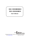
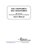
Supplementary instructions
Plug connector ISO 4400
for continuously measuring sensors
Contents
Contents
1 For your safety
1.1 Appropriate use................................................................................................................. 3
1.2 Impermissible use............................................................................................................. 3
1.3 General safety instructions................................................................................................ 3
1.4 Safety instructions for Ex areas......................................................................................... 3
2 Connecting to power supply
2.1 Wiring plan........................................................................................................................ 4
3Supplement
3.1 Technical data................................................................................................................... 5
30375-EN-140801
2
Plug connector ISO 4400 • for continuously measuring sensors
1 For your safety
1 For your safety
1.1 Appropriate use
Plug connectors belong to the accessories for level, switching and
pressure sensors. They provide a detachable connection to power
supply/signal processing for two-wire sensors. Those are sensors
whose power supply as well as measurement signal are transmitted
over one pair of wires.
1.2 Impermissible use
As a rule, plug connectors are not allowed to be used with four-wire
instruments. Those are sensors whose power supply and measurement signal are transmitted over two separate pairs of wires.
1.3 General safety instructions
The safety information in the operating instructions manual of the
respective sensor must be noted.
1.4 Safety instructions for Ex areas
Please note the Ex-specific safety information for installation and operation in Ex areas. These safety instructions are part of the operating
instructions manual and come with the Ex-approved instruments.
30375-EN-140801
For instruments with Exd or StEx approval, the use of plug connectors
is not allowed.
Plug connector ISO 4400 • for continuously measuring sensors
3
2 Connecting to power supply
2 Connecting to power supply
2.1 Wiring plan
Each respective wiring plan shows the assignment of the individual
pins of the plug connector. The chart shows the assignment of the
individual contact pins to the terminals of the sensor electronics.
1
3
3
1
2
4
2
Fig. 1: Top view of the plug connector
1
2
3
4
+ (Pin 1)
- (Pin 2)
free (Pin 3)
Screen (Pin 4)
Contact pin
Colour - connection
cable
Terminal, electronics
module
Pin 1
Black
1
Pin 2
Blue
2
Pin 3
free
free
Pin 4
Green/yellow
30375-EN-140801
4
Plug connector ISO 4400 • for continuously measuring sensors
3 Supplement
3Supplement
3.1
Technical data
Materials
Contact support
Polyamide
Housing
Polyamide
Contact surface
Housing seal
Sn
NBR
Temperature range
Plug connector - separate
-25 … +125 °C (-13 … +257 °F)
Electrical data
Rated current
16 A
Plug - mounted on the sensor
Reference voltage
Protection rating
Plug connector - separate (connected
status)
the lowest temperature is applicable
250 V AC
IP 65
30375-EN-140801
Plug connector - mounted on the sensor The lowest protection category applies
(connected status)
Plug connector ISO 4400 • for continuously measuring sensors
5
Notes
30375-EN-140801
6
Plug connector ISO 4400 • for continuously measuring sensors
30375-EN-140801
Notes
Plug connector ISO 4400 • for continuously measuring sensors
7
All statements concerning scope of delivery, application, practical use and operating conditions of the sensors and processing systems correspond to the information
available at the time of printing.
Subject to change without prior notice
© VEGA Grieshaber KG, Schiltach/Germany 2014
VEGA Grieshaber KG
Am Hohenstein 113
77761 Schiltach
Germany
Phone +49 7836 50-0
Fax +49 7836 50-201
E-mail: [email protected]
www.vega.com
30375-EN-140801
Printing date: