1
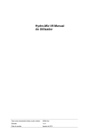
Hydro-Probe
Orbiter
User Guide
For model ORB1 – static mounting
This guide is for model ORB1 with standard sensor cable
FOR STATIC MOUNTING IN ROTATING PAN MIXERS OR ON CONVEYOR BELT
APPLICATIONS
Typical applications:
D type Eirich, Croker or Turmac mixers
Conveyor belts and material in free flow
To re-order quote part number: HD0215
Revision: 1.1.0
Revision date: March 2004
Copyright
Neither the whole or any part of the information contained in nor the product described in this documentation may be
adapted or reproduced in any material form except with the prior written approval of Hydronix Limited, hereinafter
referred to as Hydronix.
© 2004
Hydronix Limited
7 Riverside Business Centre
Walnut Tree Close
Guildford
Surrey GU1 4UG
United Kingdom
All rights reserved
CUSTOMER RESPONSIBILITY
The customer in applying the product described in this documentation accepts that the product is a programmable
electronic system which is inherently complex and which may not be completely free of errors. In doing so the customer
therefore undertakes responsibility to ensure that the product is properly installed commissioned operated and
maintained by competent and suitably trained persons and in accordance with any instructions or safety precautions
made available or good engineering practice and to thoroughly verify the use of the product in the particular application.
ERRORS IN DOCUMENTATION
The product described in this documentation is subject to continuous development and improvement. All information of a
technical nature and particulars of the product and its use including the information and particulars contained in this
documentation are given by Hydronix in good faith.
Hydronix welcomes comments and suggestions relating to the product and this documentation
ACKNOWLEDGEMENTS
Hydronix, Hydro-Probe, Hydro-Mix, Hydro-Skid, Hydro-View and Hydro-Control are Registered Trade Marks of Hydronix
Limited
TABLE OF CONTENTS
1
Introduction ................................................................................................................................ 7
1.1
Applications ....................................................................................................................... 7
1.2
Typical Mixers ................................................................................................................... 7
1.3
Description ........................................................................................................................ 7
1.4
Measuring techniques ....................................................................................................... 8
1.5
Sensor configuration ......................................................................................................... 8
1.6
Sensing arms .................................................................................................................... 8
2 Installation process for mixers ................................................................................................... 9
2.1
Assembly of sensing arm and body .................................................................................. 9
2.2
Selecting the best position for mounting sensor.............................................................. 11
2.3
Fitting the square mounting bar....................................................................................... 12
2.4
Mounting sensor and final adjustments when running .................................................... 13
2.4.1 Height adjustment ....................................................................................................... 13
2.4.2 Sensing head angle adjustment for optimum performance......................................... 14
3 Cabling to the sensor............................................................................................................... 17
4 Conveyor belt or free-fall applications ..................................................................................... 19
4.1
Hydro-Probe Orbiter for conveyor belt applications ........................................................ 19
4.2
Hydro-Probe Orbiter for free-fall applications.................................................................. 20
5 Wiring connections .................................................................................................................. 21
5.1
Analogue output .............................................................................................................. 21
5.2
RS485 multi-drop connection .......................................................................................... 22
5.3
Compatibility mode.......................................................................................................... 23
5.4
Connecting to a PC ......................................................................................................... 23
6 Configuring the sensor............................................................................................................. 25
6.1
Calibration parameters .................................................................................................... 26
6.2
Average/Hold Delay ........................................................................................................ 26
6.3
Smoothing time ............................................................................................................... 26
6.4
Slew rate + and slew rate -.............................................................................................. 26
6.5
Temperature coefficient................................................................................................... 26
6.6
Digital input/output........................................................................................................... 27
7 Sensor care ............................................................................................................................. 29
7.1
Keeping the sensing head clean ..................................................................................... 29
8 Replaceable parts.................................................................................................................... 31
8.1
Changing the sensing arm .............................................................................................. 31
8.1.1 Removing the sensing head and arm.......................................................................... 31
8.1.2 Fitting the Hydro-Probe Orbiter back into the mixer .................................................... 31
8.2
Calibrating a new arm to the sensor electronics ............................................................. 31
8.2.1 Autocal – Hydro-Probe Orbiter used in mixer applications.......................................... 31
8.2.2 Air and water calibration.............................................................................................. 33
9 Troubleshooting tips ................................................................................................................ 35
9.1
Installation ....................................................................................................................... 35
9.2
Electrical.......................................................................................................................... 35
9.3
Mixer................................................................................................................................ 35
9.4
Ingredients....................................................................................................................... 36
9.5
Workability....................................................................................................................... 36
9.6
Calibration ....................................................................................................................... 36
9.7
Mixing .............................................................................................................................. 37
10
Sensor performance............................................................................................................ 39
10.1 Adjustment of the blades................................................................................................. 39
10.2 Cement addition .............................................................................................................. 39
10.3 Water addition ................................................................................................................. 39
11
Technical specification ........................................................................................................ 41
HYDRO-PROBE ORBITER USER GUIDE
HD0215 REV 1.1.0
3
TABLE OF FIGURES
Figure 1 - The Hydro-Probe Orbiter .................................................................................................. 6
Figure 2 - Installation of sensing arm into sensor body .................................................................... 9
Figure 3 - Sensor mounted above the mixer on cross-beam .......................................................... 11
Figure 4 - Sensor mounted inside the mixer ................................................................................... 11
Figure 5 - Protective ‘roof’ placed over the sensor body................................................................. 12
Figure 6 - Removing the mounting bar clamp blocks ready for fitting to the mixer ......................... 13
Figure 7 - Height setting of the sensing arm ................................................................................... 13
Figure 8 - Adjusting the sensing head angle................................................................................... 14
Figure 9 - Setting the sensor angle for optimum performance........................................................ 14
Figure 10 - The Hydronix angle aligner for sensing face alignment................................................ 15
Figure 11 - Cabling to the sensor.................................................................................................... 17
Figure 12 - Mounting the Hydro-Probe Orbiter for conveyor belt applications ................................ 19
Figure 13 - Mounting the Hydro-Probe Orbiter for free-fall applications (conveyor and silo) .......... 20
Figure 14 - Sensor cable (0090A) connection ................................................................................ 22
Figure 15 - Multi-drop connection ................................................................................................... 22
Figure 16 - Compatibility mode ....................................................................................................... 23
Figure 17 - RS232/485 converter connections ............................................................................... 24
Figure 18 - Din rail mounting RS232/RS485 converter................................................................... 24
Figure 19 - The Hydronix Autocal Dongle....................................................................................... 32
Figure 20 - Connecting the Hydronix Autocal Dongle for calibration .............................................. 32
Figure 21 - Air-water calibration...................................................................................................... 33
HYDRO-PROBE ORBITER USER GUIDE
4
HD0215 REV 1.1.0
HYDRO-PROBE ORBITER USER GUIDE
HD0215 REV 1.1.0
5
Hose clamp
tube
Cable
25-35mm square
mounting bar
(provided by
customer)
Protective hose
for cable
Clamp block
Sensor body
Arm clamp
Replaceable
sensing arm
Ceramic face plate
Sensing head
225mm
Rapid response
temperature sensor
156mm
Two lengths
of arm are
available –
Overall length
560mm or
700mm
Figure 1 - The Hydro-Probe Orbiter
HYDRO-PROBE ORBITER USER GUIDE
6
HD0215 REV 1.1.0
Chapter 1
1 Introduction
1.1
Applications
The Hydro-Probe Orbiter may be used for three different types of application:
Type 1:
For static mounting of the Hydro-Probe Orbiter sensor (ORB1) in rotating mixers or
for conveyor belts or material in free fall applications
Type 2:
For a rotating mounting in static pan mixers, using a rotating connector for
connecting the cable to the Hydro-Probe Orbiter
Type 3:
Also, for a rotating mounting using a battery-powered sensor (ORB1MB) with radio
modem communication. This is for applications where it is not possible to
electrically connect the sensor to the outside of the mixer via a rotating connector.
This manual is written for Application Type 1:
FOR THE STATIC MOUNTING OF THE HYDRO-PROBE ORBITER IN ROTATING PAN
MIXER OR CONVEYOR BELT APPLICATIONS USING THE STANDARD SENSOR CABLE
(PART NO 0090A)
1.2
Typical Mixers
D type Eirich, Croker and Turmac mixers
1.3
Description
The Hydro-Probe Orbiter is the most innovative sensor ever to reach the market. With an easily
replaceable sensing head that slices through the mix, the Hydro-Probe Orbiter provides a rapid
and representative measurement of both moisture content and temperature of the material.
Utilising the latest digital technology, the Hydro-Probe Orbiter combines accuracy and speed to
provide a meaningful reading that is unachievable with static mounted sensors.
The main sensor electronics are housed in the sensor body, separate from the hard wearing
replaceable sensing arm and head. This provides many distinct advantages with the following
key features and benefits:
•
Small streamlined sensing head cuts cleanly and smoothly through the material
without a build-up, providing a smooth and clean signal.
•
Rapid response temperature measurement provided from a thermally ‘insulated’
temperature sensor in sensing head end plate.
•
Easily replaceable sensing arm and hardened wear head, with easy calibration
procedure for matching new microwave sensing head and arm to main electronics.
HYDRO-PROBE ORBITER USER GUIDE
HD0215 REV 1.1.0
7
1.4
Measuring techniques
The Hydro-Probe Orbiter uses the very latest digital microwave techniques that provide a more
sensitive measurement compared with other analogue techniques. The frequency has been
selected to provide the optimum compromise between penetration of measurement and
accuracy. The penetration of measurement is approximately 100mm in dry materials such as
sand.
The output is linear for most materials with the ability to measure up to the point of saturation for
the material concerned.
1.5
Sensor configuration
As with other Hydronix digital microwave sensors, the Hydro-Probe Orbiter may be remotely
configured using the Hydro-Link or Hydro-Com diagnostics software.
1.6
Sensing arms
The Hydro-Probe Orbiter is available in various lengths. Standard lengths are 560mm or
700mm, note that this length refers to the overall height of the Hydro-Probe Orbiter, as shown in
Figure 1. Other lengths can be made to order.
An additional feature with the longer (700mm) sensing arm is a reinforcing collar that fits over
the top of the arm, see Figure 2. This is included to increase the strength of the arm.
CAUTION – NEVER HIT THE SENSING ARM
HYDRO-PROBE ORBITER USER GUIDE
8
HD0215 REV 1.1.0
Chapter 2
2 Installation process for mixers
The Hydro-Probe Orbiter may be clamped to a vertically or horizontally mounted 25-35mm
square bar. The bar should be supplied and suitably mounted by the customer or agent
installing the sensor.
The installation involves the following processes:
•
Assembly of sensing arm and body (Section: 2.1)
•
Selecting the best position for mounting the sensor (Section: 2.2)
•
Fitting of the square mounting bar (Section: 2.3)
•
Mounting the sensor and final adjustments when running (Section: 2.4)
•
Cabling to the sensor (Chapter 3)
2.1
Assembly of sensing arm and body
The sensing arm and electronics body are shipped unattached. They need to be connected
before installation into the mixer.
•
Lay the main electronics body on a clean, flat surface
•
Loosen the 4 arm clamp bolts on the electronics body and remove the locking bolt (A).
•
Fit the two ‘O’ rings. These need to be located inside the clamp blocks up against the
step as shown in Figure 2
•
Ensure that the red mark on the electrical connector at the top of the sensing arm is
on the same side of the arm as the ceramic faceplate. The connector can easily be
rotated by hand if required.
Clamp block –
4 bolts
Two ‘O’ rings have to
be installed to the end
of the barrel
Strengthening
collar
Locking bolt ‘A’ to
be removed
Figure 2 - Installation of sensing arm into sensor body
HYDRO-PROBE ORBITER USER GUIDE
HD0215 REV 1.1.0
9
•
Lay the sensing arm on the same clean, flat surface with the ceramic faceplate facing
upwards, aligned with the hole in the head unit.
•
For ease of fitting, apply a small amount of silicone grease to the connector end of the
arm or around the two ‘O’ rings.
•
Gently locate the connector at the top of the sensing arm in the hole in the head unit,
such that the connector lines up with its socket in the head unit. Push the sensing
head home into the main body unit.
•
Tighten the arm clamp nuts up to a point where it is still possible to rotate the arm by
hand – these are not fully tightened until the sensing head has been aligned at the
correct angle after the Hydro-Probe Orbiter has been installed in the mixer.
•
If the arm is a replacement then a recalibration procedure will need to be carried out.
See section 8.2 - Calibrating the new arm to the sensor electronics
HYDRO-PROBE ORBITER USER GUIDE
10
HD0215 REV 1.1.0
2.2
Selecting the best position for mounting sensor
Depending on the mixer type, the sensor may need to be fitted either inside (Figure 4), or above
the mixer (Figure 3).
A square support bar needs to be fitted securely and rigidly to a cross member or the static side
wall of the mixer to provide solid support for the Hydro-Probe Orbiter.
A protective ‘roof’ may be provided over the sensor body to protect the sensor from falling
materials and prevent unnecessary build up of materials on the sensor body (Figure 5).
The sensing head is to be positioned in an area where the flow of material is the smoothest.
Normally this is a quarter or a third of the distance in from the outer edge of the mixer wall.
(Figure 9).
Supporting cross
member (supplied
by customer)
Figure 3 - Sensor mounted above the mixer on cross-beam
Reinforcement
may be required
Figure 4 - Sensor mounted inside the mixer
HYDRO-PROBE ORBITER USER GUIDE
HD0215 REV 1.1.0
11
Protective
‘roof’
Figure 5 - Protective ‘roof’ placed over the sensor body
2.3
Fitting the square mounting bar
A 25-35mm square bar should be very firmly welded to the appropriate cross member, or static
side wall of the mixer. It should be suitably reinforced to provide a rigid fixing that will withstand
the thrust generated on the sensor head and body from the moving material. Ensure that the
bar is perpendicular to the floor in both planes.
Undo and remove the 4 bolts securing the pair of clamp blocks to the head unit (for clamping
the unit to the square bar), and remove the pair of clamp blocks as shown in Figure 6.
Depending on the configuration, the clamp blocks may need to be rotated for either vertical or
horizontal fixing to the square bar.
HYDRO-PROBE ORBITER USER GUIDE
12
HD0215 REV 1.1.0
Figure 6 - Removing the mounting bar clamp blocks ready for fitting to the mixer
2.4
Mounting sensor and final adjustments when running
2.4.1
Height adjustment
The height may be adjusted by slackening the clamp blocks and sliding the body up and
down the square support bar.
The recommended height for typical applications is 50mm above the floor of the mixer
(Figure 7). This height can be set using the angle aligner, which has a width of 50mm.
The correct length of arm should be selected to allow the sensing head to sit a minimum of
50mm above the floor of the mixer and to ensure that the ceramic faceplate is in the full flow
of the mix
When adjusted to the desired height, securely tighten the clamp block bolts to a torque of
60Nm (44lb/ft). It is essential to ensure the Nordlock washers are fitted to the clamp bolts
so that the sensor is securely retained on the square bar.
Sensing head
Minimum level of material
Ceramic
faceplate
50mm
Mixer floor
Figure 7 - Height setting of the sensing arm
HYDRO-PROBE ORBITER USER GUIDE
HD0215 REV 1.1.0
13
2.4.2
Sensing head angle adjustment for optimum performance
With the 4 arm clamp nuts loose, the sensing arm can be rotated through an angle of
approximately 300º (Figure 8). The sensing arm is fitted with a mechanical stop to protect
the internal cables from being over-rotated. If this stop prevents the faceplate from being
adjusted properly, then remount the Hydro-Probe Orbiter main body on the square bar at a
different angle. This will then allow the arm to be adjusted correctly.
Figure 8 - Adjusting the sensing head angle
The angle of the sensing head face should be adjusted to provide consistent compaction of
material against the ceramic measuring face and at an angle that avoids build up of material
on the sensing head.
Figure 9 - Setting the sensor angle for optimum performance
HYDRO-PROBE ORBITER USER GUIDE
14
HD0215 REV 1.1.0
•
An angle of 55º generally provides good results. Use the angle aligner provided to set
the angle (Figure 10).
•
It has been found in some rotating pan mixers an angle of approximately 65° to the
mixer centre is more appropriate to prevent too much build up of material.
•
Ensure all clamp bolts are tightened to a torque of 28Nm (21lb/ft) after adjustment.
Aligner positioned against face plate
pointed towards the mixer centre.
Figure 10 - The Hydronix angle aligner for sensing face alignment
IMPORTANT:
Once the alignment of the sensing arm is changed inside a mixer, the resultant density
change of material passing the sensing head will have an effect on the measurement. It
is therefore advisable to recalibrate the recipes before continuing batching.
HYDRO-PROBE ORBITER USER GUIDE
HD0215 REV 1.1.0
15
Notes:
HYDRO-PROBE ORBITER USER GUIDE
16
HD0215 REV 1.1.0
Chapter 3
3 Cabling to the sensor
The cable to the sensor must be protected from the actions of the mixer and from damage that
may be caused by the loading of aggregates into the mixer. It is recommended that the cable
be sheathed in a heavy-duty rubber hose that is firmly secured at either end using hose clamps.
Securing along the underside of the mixer arm, as shown in Figure 11, will also protect the
cable from the incoming load.
Hose clamp
32mm ID
Protective Rubber
Hose
Hose clamp
Figure 11 - Cabling to the sensor
HYDRO-PROBE ORBITER USER GUIDE
HD0215 REV 1.1.0
17
Notes:
HYDRO-PROBE ORBITER USER GUIDE
18
HD0215 REV 1.1.0
Chapter 4
4 Conveyor belt or free-fall applications
THE HYDRO-PROBE II IS VERY POPULAR IN FREE-FALL AND CONVEYOR BELT
APPLICATIONS. IF THE MATERIAL IS VERY ABRASIVE, THEN THE HYDRO-PROBE
ORBITER PROVIDES A GOOD ALTERNATIVE.
4.1
Hydro-Probe Orbiter for conveyor belt applications
In concept, the sensor may be fitted in a similar manner, with the sensing face angled at
approximately 35º to the flow of material or 55º to line perpendicular to the direction of the flow.
Flow of material
25 – 45 º
Figure 12 - Mounting the Hydro-Probe Orbiter for conveyor belt applications
HYDRO-PROBE ORBITER USER GUIDE
HD0215 REV 1.1.0
19
4.2
Hydro-Probe Orbiter for free-fall applications
Fitting should be as indicated in the drawings below
Sensing arm
(end-on view)
Hydro-Probe
Orbiter body
Hydro-Probe
Orbiter body
Sensing arm in
flow of material
Figure 13 - Mounting the Hydro-Probe Orbiter for free-fall applications (conveyor and silo)
HYDRO-PROBE ORBITER USER GUIDE
20
HD0215 REV 1.1.0
Chapter 5
5 Wiring connections
The Hydro-Probe Orbiter is connected using a 4 metre cable (part no 0090A). An extension
cable (twisted pairs) from the plant control room should be provided by the customer or agent
installing the sensor. Up to 6 twisted pairs may be required dependent on installation
requirements. It is recommended that a high quality cable with a good braid and foil screen is
used to minimise electrical interference, containing 22 AWG, 0.35mm2 conductors.
Recommended cable types are Belden 8306 or Alpha 6377. The cable screen must be
connected at the sensor end only, and therefore it is essential that the sensor body has a good
connection to an electrical earth.
The extension cable run from the sensor to the control unit must be separate from any heavy
equipment power cables, particularly the power cable for the mixer. Failure to separate the
cable runs can lead to signal interference.
5.1
Analogue output
A DC current source generates an analogue signal proportional to any of a number of
selectable parameters (e.g. filtered unscaled, filtered moisture, average moisture, etc. See
section 6, or Hydro-Link manual for details). Using Hydro-Link, Hydro-Com or direct computer
control the output may be selected to be:
•
4 – 20 mA
•
0 – 20 mA
This may be configured as a 0 – 10 V DC voltage output if a 500 ohm
resistor is connected across the analogue output and return wires (see
Figure 14)
NOTE: If a 0-10V signal is required, connect the resistor at the control room end.
Twisted Pair
Number
1
1
2
2
3
3
4
4
5
5
6
6
MIL spec
pins
A
B
C
-D
E
F
G
J
-D
K
H
Sensor connections
Cable colour
+15-30V DC
0V
1st Digital input
1st Analogue Positive (+)
1st Analogue Return (-)
RS485 A
RS485 B
2nd Digital input
2nd Analogue Positive (+)
2nd Analogue Return (-)
Screen
Red
Black
Yellow
Black (Cut back)
Blue
Black
White
Black
Green
Black (Cut back)
Brown
Black
Screen
Table 1 – Sensor cable (0090A) connection
Applies to analogue and multi-drop connections
HYDRO-PROBE ORBITER USER GUIDE
HD0215 REV 1.1.0
21
D
K
J
G
F
D
E
brown blk green blk white blue
B
A
blk yellow blk
C
red
H
Junction box
screen
Do not connect shield
at control cabinet.
500R resistor for
0-10V
Positive Return
+
-
2nd Analogue Output
D2
2nd Digital
Input
B
A
RS485
Postive
Return
+
-
1st Analogue Output
D1
1st Digital
Input
0V
+VE
-
+
Supply (15-30V DC)
Control Room Wiring
Figure 14 - Sensor cable (0090A) connection
NOTE: The cable screen is grounded at the sensor and therefore should not be
connected at the control system end. It is important to ensure that the plant where the
sensor is installed is properly grounded. If there is any doubt, a connection from the
cable screen to ground should be provided at the junction box.
5.2
RS485 multi-drop connection
The RS485 serial interface allows up to 16 sensors to be connected together via a multi-drop
network. Each sensor is connected using a waterproof junction box.
The control system is generally connected to the nearest junction box
Cable – 0090A (4m)
H J G F
E
DC
B
A
To PC or plant
control device
From other
sensors
Digital inputs (optional)
Figure 15 - Multi-drop connection
HYDRO-PROBE ORBITER USER GUIDE
22
HD0215 REV 1.1.0
5.3
Compatibility mode
Compatibility mode allows a Hydro-Probe Orbiter to connect to a Hydro-Control IV or HydroView. To operate in this mode the ‘output type’ needs to be set to compatibility using HydroLink or Hydro-Com, see section 6. The 500 ohm resistor is required to convert the analogue
current output to a voltage signal. This should be fitted as shown at the Hydro-Control IV/
Hydro-View. The required connections are shown below in Figure 16.
Cable – 0090A (4m)
H
JG
F
E
D
C
B
A
+15V
0V
Signal
Return
500 Ohm resistor
Hydro-Control IV or
Hydro-View Connector
1
2
3
4
5
6
7
8
9
10
11
12
Figure 16 - Compatibility mode
5.4
Connecting to a PC
An RS232-485 converter is required to connect one or more sensors to a PC. There are three
types of converter supplied by Hydronix. All operate identically, but come in a different package
to suit a variety of connection types and applications.
For single sensor applications, the twisted pair RS485 wires from the sensor can be either
terminated in a 9-pin male D-type converter (part no 0049) or a terminal block connected
converter (part no 0049B). These two converters are shown in Figure 17.
For multi-sensor applications, it is recommended that a converter that has an external power
supply is used, such as the converter show in Figure 18, which is designed for industrial
applications and is DIN-rail mounted. Note that this unit has an additional RJ-11 type RS232
port if the customer wishes to connect to a PC using a suitable cable.
RS485 line termination will not normally be required in applications with up to 300m of cable.
For longer lengths, connect a resistor (approximately 100 ohm) in a series with a 1000 pF
capacitor across each end of the cable.
It is recommended that the RS485 signals be run to the control room even if they are unlikely to
be used. This is because it will facilitate the use of diagnostic software should the need arise.
HYDRO-PROBE ORBITER USER GUIDE
HD0215 REV 1.1.0
23
RS485
RS485 (A)
5
9
4
8
Connect to
PC serial
port
3
7
2
6
RS485 (B)
RS232
1
Hydronix Part No 0049
RS485
RS485 (A)
RS232
1
Connect to
PC serial
port
2
RS485 (B)
3
4
5
Hydronix Part No 0049B
6 dipswitches control the configuration of the converter. For both
the 0049 and 0049B these should be set to:
Switch 1 ON
Switch 2 OFF
Switch 3 ON
Switch 4 OFF
Switch 5 OFF
Switch 6 OFF
Figure 17 - RS232/485 converter connections
KD485 – STD
Hydronix Part No
0049A
P1
PC
or
Control System
RS232
(full-duplex)
Host System
9-way D-Type PC
connector
3
TX
2
RX
7
RTS
5
GND
Power Supply
7 – 35V DC
Hydro-Probe
Orbiter
P2
1
1
F RS485(A)
F RS485(A)
2
2
G RS485(B)
G RS485(B)
3
3
4
4
H
H
5
5
6
6
Dip Switch
Settings
7 +
8 -
RJ11
RS232
port
Figure 18 - Din rail mounting RS232/RS485 converter
HYDRO-PROBE ORBITER USER GUIDE
24
HD0215 REV 1.1.0
Hydro-Probe
Orbiter
1 2 3 4
Chapter 6
6 Configuring the sensor
The Hydro-Probe Orbiter may be configured using the Hydro-Link or Hydro-Com software.
The complete set of default parameters is shown in the table below:
Hydro-Probe Orbiter
Parameter
Range/options
Standard Default
Moisture calibration
A
B
C
SSD
0.0000
0.2857
-4.0000
0.00
Signal processing
configuration
Smoothing time
Slew rate +
Slew rate -
7.5 sec
Light
Light
1.0, 2.5, 5.0, 7.5, 10
Light, Medium, Heavy, Unused
Light, Medium, Heavy, Unused
Averaging configuration
Average hold delay
High limit (m%)
Low limit (m%)
High limit (us)
Low limit (us)
0 sec
30.00
0.00
100.00
0.00
0.0, 0.5, 1.0, 1.5, 2.0, 5.0
0 – 100
0 – 100
0 – 100
0 – 100
Input/output configuration
Output type
Output variable 1
0 – 20 mA (0 – 10V)
Filtered unscaled
Output variable 2
Material temperature
High %
Low %
Input Use 1
20.00
0.00
Average/hold
Input/output Use 2
Unused
0-20mA, 4-20mA, Compatibility
Filtered moisture %, Average
moisture %, Raw moisture %, Raw
unscaled, filtered unscaled, Average
unscaled, Material temperature
Filtered moisture %, Average
moisture %, Raw moisture %, Raw
unscaled, filtered unscaled, Average
unscaled, Material temperature
0 – 100
0 – 100
Average/hold, Average/filtered,
Moisture/temp, Unused
Unused, Moisture/temp, Bin empty,
Data invalid, Probe OK
Temperature compensation
Electronics temp. coeff
Resonator temp. coeff
0.002
0.0075
Table 2 - Hydro-Probe Orbiter default parameters
Note: When connected to a Hydro-Control IV or Hydro-View the output type should be
set to compatibility.
HYDRO-PROBE ORBITER USER GUIDE
HD0215 REV 1.1.0
25
6.1
Calibration parameters
The default calibration parameters in Table 2 are Hydronix standard sand calibration set.
These values will be used to convert the unscaled reading to a moisture reading according to
the formula:
Moisture (%) = A x (unscaled reading)2 + B x (unscaled reading) + C
The A, B and C coefficients are only active when either:
•
The analogue output is set to give Raw, Filtered or Average moisture.
•
Raw, Filtered or Average moistures are read from the RS485 link
The recommended analogue output type is ‘Filtered Unscaled’. In this case the calibration
parameters will have no effect.
NOTE: The analogue and RS485 output work independently of each other. Therefore if
Raw, Filtered or Average moisture levels are requested via the RS485 link, the analogue
output can still be set to give an unscaled output (which will not use the A, B and C
values) and visa versa.
6.2
Average/Hold Delay
This parameter would only be used for applications where the Hydro-Probe Orbiter is replacing
the Hydro-Probe II, for example in high wear environments. In mixer applications this should be
set to zero (0) for the Hydro-Probe Orbiter.
6.3
Smoothing time
This defines the amount of filtering on the output signal. The smoothing time defines the time
taken to get 50% of the final value in response to a step input. A value of 7.5 seconds is normal
for most mixer situations
6.4
Slew rate + and slew rate -
These slew rates are used to limit the effect of rapid transient signals due to mixing action.
There are three settings available: Light, Medium and Heavy, these correspond to 5, 2.5 and
1.25 unscaled units per second.
6.5
Temperature coefficient
This parameter is used to correct for thermal drifts in the electronics when used in hot
environments or with hot materials. It should not normally be altered.
HYDRO-PROBE ORBITER USER GUIDE
26
HD0215 REV 1.1.0
6.6
Digital input/output
The Hydro-Probe Orbiter has two digital lines. One line can be configured as an input and the
other can be either an input or output.
Input Use 1
1.
2.
3.
4.
Unused – the status of the line is ignored
Average/hold (default) – the readings are averaged and when switched the analogue
output holds the average value.
Average/filtered – the readings are averaged and when switched the analogue output
returns to the filtered output.
Moisture/temperature – switch the analogue output between a signal proportional to
moisture and a signal proportional to external (material) temperature.
Input/output Use 2
1.
2.
3.
4.
5.
Unused (default) – the status of the line is ignored
Moisture/temperature - Switch the analogue output between a signal proportional to
moisture and a signal proportional to external (material) temperature.
Bin empty (output)
Data invalid (output)
Probe OK (output)
HYDRO-PROBE ORBITER USER GUIDE
HD0215 REV 1.1.0
27
Notes:
HYDRO-PROBE ORBITER USER GUIDE
28
HD0215 REV 1.1.0
Chapter 7
7 Sensor care
7.1
Keeping the sensing head clean
Ensure there is no permanent build up of material over the sensing head and arm. If the angle
of the face of the sensing head is correctly adjusted, then the continual movement of fresh
material against it should normally keep it clean.
At the end of the shift, or if there is a significant gap in production, it is advisable to hose or wipe
the arm and head to ensure no hard build-up occurs.
It is recommended that a high pressure water cleaning system is used to clean the sensor.
However, although the Hydro-Probe Orbiter is waterproof, its seals will not prevent the ingress
of water from high pressure equipment nozzles that are held in close proximity to the sensor.
Keep all high pressure water sprays at least 300mm away from the sensor.
CAUTION – NEVER HIT THE SENSING ARM
HYDRO-PROBE ORBITER USER GUIDE
HD0215 REV 1.1.0
29
Notes:
HYDRO-PROBE ORBITER USER GUIDE
30
HD0215 REV 1.1.0
Chapter 8
8 Replaceable parts
8.1
Changing the sensing arm
The sensing arm is a replaceable item. The wear life of the arm is dependent on the materials
in which it is used, the mixer, and of course on the amount of use.
Wear life may be extended by taking precautions as set out in the previous chapter. However,
periodically, either through accidental damage or excessive wear, it may be necessary to
replace the head and arm.
8.1.1
Removing the sensing head and arm
•
Undo the clamp bolts securing the sensor body to the square support bar.
•
Remove the entire sensor body and arm and take to a clean environment.
•
Lay the sensing arm on a clean flat surface.
•
Undo the arm clamp nuts on the sensor body and pull out the worn sensing arm.
•
Attach the new sensing arm by following the installation instructions in this guide (See
section 2.1)
8.1.2
Fitting the Hydro-Probe Orbiter back into the mixer
Follow the instructions in Chapter 2, ensuring both the height from the mixer floor and the
angle of the sensing head are set correctly.
8.2
Calibrating a new arm to the sensor electronics
Recalibration is necessary after fitting a new arm to the sensor electronics. For mixer
applications, a calibration called AUTOCAL is sufficient, although there are other ways in case
the customer has no facility for this. For conveyor belts or freefall applications, a separate AIR
and WATER calibration is needed.
8.2.1
Autocal – Hydro-Probe Orbiter used in mixer applications
During any Autocal, the ceramic face must be clean, dry and free from obstruction.
This calibration can be performed in three ways
•
Using Hydro-Com PC utility
The sensor should be connected to a computer (see section 5.4) running a suitable
Hydronix PC utility such as Hydro-Com. The configuration section of these programs
has an Autocal facility. Once selected, the Autocal will be completed in approximately
60 seconds and the sensor is ready for use in the mixer. Note that Hydro-Link does
not have Autocal feature.
•
Using the Hydro-Control V
The Hydro-Control V has the capability to perform an Autocal calibration in the sensor
configuration page. From the main window this can be accessed by the following:
MORE > SETUP > (enter pass-code 3737) > DIAG > CONF > CALIB. Note this
feature is only available on Hydro-Control V firmware versions 4.1 and later, and
Autocal will only work for the Hydro-Probe Orbiter, no other Hydronix sensors.
HYDRO-PROBE ORBITER USER GUIDE
HD0215 REV 1.1.0
31
•
Using the Hydronix Autocal Dongle
The Autocal Dongle as shown in Figure 19, has been designed for applications where
there is no RS485 serial link and the customer is using the analogue output from the
sensor. This calibration is completed by connecting the dongle in-line between the
cable and the sensor body, as shown in Figure 20.
Figure 19 - The Hydronix Autocal Dongle
Cable
Dongle
Sensor body
Figure 20 - Connecting the Hydronix Autocal Dongle for calibration
The simple procedure outlined below should take less than one minute to complete:
1.
2.
3.
4.
Ensure the ceramic face plate is facing upwards and is completely clean and dry
Connect the Autocal Dongle to the sensor body and cable as shown in Figure 20. The
Autocal Dongle should begin flashing (red) bright-dim-bright for 30 seconds
After 30 seconds the Autocal Dongle should start flashing on-off-on
At this stage it is important to keep away from the ceramic faceplate
After approximately 20 seconds the Autocal Dongle should illuminate constantly. The
calibration is finished and the Hydro-Probe Orbiter is ready to be fitted back into the
mixer. Disconnect the Autocal Dongle and reattach the cable for normal use.
If the Autocal Dongle continues to flash on-off-on as in stage 3, then the calibration was
unsuccessful due to variation during its measurement stage (stage 4). If this is the case,
disconnect the Autocal Dongle from the sensor body and cable, and repeat steps 1 – 4.
HYDRO-PROBE ORBITER USER GUIDE
32
HD0215 REV 1.1.0
8.2.2
Air and water calibration
Can be used for mixer applications; required when the Hydro-Probe Orbiter is used on
conveyor belts and freefall applications
Using any of the available Hydronix configuration utilities (Hydro-Link, HydroNet-View, HydroCom).
The calibration is performed by making separate readings in air and water. With the sensor
connected to a computer (see section 5.4), the Hydronix PC-based utility can be used to
make the measurements and update the sensor in the configuration section.
The air reading should be made with the face-plate clean, dry and free from obstructions. On
the appropriate tab of the application software press the New Air or High button. The software
will make a new air measurement.
The water reading should be carried out in a bucket filled with a clean brine solution. This
solution should be made up from water with 0.5% by weight of salt (e.g. 10 liters of water to
be mixed with 50gm of salt). The level of water needs to cover the ceramic face-plate, and at
least 200mm of water is needed in front of the ceramic. It is suggested that the sensor is held
in the bucket offset to one side with the face towards the centre of the bucket (see Figure 21),
hence the measurement is carried out with a full bucket of water in front. Press the New
Water or Low button. The software will make a new water measurement.
Once both readings are made, the sensor can be updated by pressing the update button in
the application software and it is then ready for use.
`
200mm min.
Sensor in
the water
bath
Sensor
Minimum water depth 200mm
Figure 21 - Air-water calibration
IMPORTANT:
Once the alignment of the sensing arm is changed inside a mixer, the resultant density
change of material passing the sensing head will have an effect on the recipe. This
would apply when a new arm is fitted, despite pointing the faceplate in the same
approximate direction as the previous installed arm. It is therefore advisable to
recalibrate the recipes before continuing batching.
HYDRO-PROBE ORBITER USER GUIDE
HD0215 REV 1.1.0
33
Notes:
HYDRO-PROBE ORBITER USER GUIDE
34
HD0215 REV 1.1.0
Chapter 9
9 Troubleshooting tips
These tips are intended as suggestions for troubleshooting when problems occur with the water
control system.
9.1
Installation
•
Fit the sensor with a 50 mm gap between the bottom of the Hydro-Probe Orbiter and
the mixer floor.
•
Fit away from the water, cement and aggregate inlets.
•
If the Hydro-Probe Orbiter performance is suspect, if possible compare the signal from
the sensor (using Hydro-Com or Hydro-Link) to the calculated moisture content. This
will identify if the problem is with the Hydro-Probe Orbiter or the control system.
9.2
Electrical
•
Ensure that the cable is of suitable quality – the minimum specification is twisted pairs
of 22 AWG (0.35mm2) conductors, screened with aluminium/polyester foil and 65%
minimum coverage braid – Belden 8306 or equivalent.
•
When using the analogue output, it is advisable to take the RS485 cable back into the
control cabin. This can be particularly useful over the life of the equipment for
diagnostic purposes and takes the minimum of effort and cost at the time of
installation.
•
Route the signal cable away from power cables, in particular the mixer power supply.
•
Check the mixer is properly grounded.
•
The signal cable should only be grounded at the mixer end.
•
Ensure the cable shield is not connected at the control cabin end.
•
Ensure there is continuity of the shield through any junction boxes.
•
Keep the number of joints in the cable to a minimum.
•
Note that there is a M4 threaded hole provided on the back plate of the Hydro-Probe
Orbiter body for a ground connection.
9.3
Mixer
•
Look at the mixing process. Check how the water disperses. If water sits on top of
the aggregates for a time before dispersing, then spray bars will be required to get it
into the mixer quicker to shorten the mix time.
•
Spray bars are far better than single water inlets. The greater the area of water inlet,
the faster it mixes in.
HYDRO-PROBE ORBITER USER GUIDE
HD0215 REV 1.1.0
35
9.4
Ingredients
•
If the aggregate masses are not corrected for high moisture contents, the
aggregate/cement ratio will change considerably, having a bad effect on workability
and concrete performance.
•
If the aggregates are very wet, then there may be more water in the aggregates than
the mix requires. This could be the case at the beginning of the day due to water
drainage in the storage bin.
•
The moisture content of the aggregates must be above their saturated surface dry
(SSD) moisture content before loading into the mixer. Microwave sensors measure
moisture content accurately above the SSD value of a material because measurement
loses linearity below SSD. Mixing performance is also increased when the
aggregates are above their SSD value upon loading, as the cement can absorb free
moisture prior to water addition.
•
Beware of hot cement, it can affect water demand and hence moisture content.
•
Changes in ambient temperature also affect water demand.
9.5
Workability
•
The Hydro-Probe Orbiter measures moisture, it does not measure workability, or
someone’s perception of workability.
•
Changes in many factors affect workability but these changes may not affect moisture
content:
o
o
o
o
o
o
o
9.6
Aggregate grading.
Aggregate/cement ratio.
Admixture dosage and dispersion.
Ambient temperature.
Coarse/fine ratio.
Water/cement ratio.
Ingredient temperatures.
Calibration
•
Leave out the admixtures when calibrating.
•
If the wet mix time is shortened for production, ensure the full time is used during
calibration.
•
Different batch recipes may be required for large variations in batch volume.
•
Calibrate when conditions/ingredients are typical e.g., not first thing in the morning
when the aggregates are very wet, or when the cement is hot.
•
When using a calibration-based water addition method, obtaining a correct dry
reading is essential.
o
o
o
Signal must be stable.
Dry mix time must be long enough to obtain signal stability.
Good measurement requires time.
HYDRO-PROBE ORBITER USER GUIDE
36
HD0215 REV 1.1.0
9.7
Mixing
•
Minimum mix times are a function of the mix design (ingredients and mixer) not just
the mixer.
•
Different mixes need different mix times.
•
Keep batch sizes as consistent as possible e.g. three batches of 2.5m3 + 2.5m3 +
1.0m3 is not as good as 3 batches of 2.0m3.
•
Keep the premix time as long as possible, at the detriment of the wet mix time if
necessary.
•
The shortest mix time is generally obtained from this mix order:
o
o
o
o
o
o
o
o
o
Load aggregates (including steel or rigid plastic fibres if used).
Load microsilica slurry, if used.
Load cement just after aggregates start (and after micro silica slurry, if used).
Run cement and aggregates together (and silica fume powder, if used).
Finish cement before aggregates.
Allow sufficient dry mix time to obtain a good stable signal.
Measure moisture content.
Load water and admixtures.
Wet mix until the signal is stable.
REMEMBER – DO NOT HIT THE CERAMIC – IT IS EXTREMELY WEAR RESISTANT, BUT
BRITTLE
HYDRO-PROBE ORBITER USER GUIDE
HD0215 REV 1.1.0
37
Notes:
HYDRO-PROBE ORBITER USER GUIDE
38
HD0215 REV 1.1.0
Chapter 10
10 Sensor performance
The moisture reading from the sensor can only indicate what is happening in your mixer. The
speed of reading or the time taken to reach a steady reading when the materials are
homogenous reflects the effectiveness of the mixer. By taking some simple precautions, the
overall performance can be considerably improved and the cycle time reduced with consequent
financial savings
10.1 Adjustment of the blades
•
Ensure the mixer blades are regularly adjusted to comply with the manufacturers
recommendations (normally 2mm clear of the floor), with the consequent benefits:
o
o
o
All the residual mix is discharged when emptying the mix
Mixing action close to the floor of the mixer is improved, thereby improving the
reading of the sensor
Reduced wear on mixer floor plates
10.2 Cement addition
•
Mixing the fine cement particles in with the relatively coarse particle size of the sand
and aggregates is a tough job. When possible cement addition should commence a
few seconds after the loading of the sand and aggregates. Folding in the materials
together in this way will greatly assist the mixing process.
10.3 Water addition
•
To facilitate the mixing action, the water should be sprayed in over as wide an area as
possible, rather than discharged at one point. Remember excessively rapid water
addition will increase the wet mix time required to reach homogeneity. Therefore
there is an optimum rate of water addition for achieving minimum mix cycle time.
•
Commencement of water addition should only start after the cement has been
substantially mixed in with the aggregates. Cement powder lying on the surface of
the aggregates will absorb the water turning into a wet paste which will be more
difficult to disperse uniformly throughout the mix
HYDRO-PROBE ORBITER USER GUIDE
HD0215 REV 1.1.0
39
Notes:
HYDRO-PROBE ORBITER USER GUIDE
40
HD0215 REV 1.1.0
Chapter 11
11 Technical specification
11.1 Mechanical Dimensions
•
ORB1 Housing: 156 x 225 mm
•
Sensing arm: 104.5 x 34 mm (length of arm to suit mixer, usually 560 mm or 700mm)
11.2 Construction
•
Body: stainless steel (AISI 304)
•
Sensing head: Hardened stainless steel (wear resistant surface coating also available)
•
Faceplate: Alumina ceramic
11.3 Penetration of field
•
Approximately 75 – 100 mm dependent on the material
11.4 Operating temperature range
•
0 – 60º C. The sensor will not measure in frozen materials
11.5 Supply Voltage
•
+15V to 30 V DC, 4 watt max.
11.6 Connections
11.6.1
Sensor cable
•
6 pairs twisted (12 cores total) screened (shielded) cable with 22 AWG, 0.35mm2
conductors
•
Screen (shield): Braid with 65% minimum coverage plus aluminium/polyester foil
•
Recommended cable types: Belden 8306, Alpha 6373
•
Maximum cable run: 100 m separate to any heavy equipment power cables
11.6.2
•
Digital (serial) communications
Opto-isolated RS485 2 wire port – for communications including changing operating
parameters and sensor diagnostics
11.7 Analogue output
•
Two configurable outputs 0 - 20mA or 4 - 20mA current loop source available for moisture
and temperature. Also may be converted to 0 – 10 V DC
11.8 Digital inputs/outputs
•
Two lines available for batch averaging, start/stop, or temperature multiplexing. One line
may also be used as an output status flags indicating ‘out of range’, ‘bin empty’ or ‘probe
ok’
11.9 Grounding
•
Ensure equipotential bonding of all exposed metalwork. In areas of high lightning risk,
correct and adequate protection should be used.
HYDRO-PROBE ORBITER USER GUIDE
HD0215 REV 1.1.0
41