1
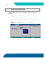
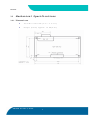
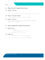
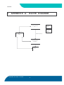
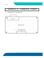
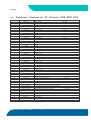
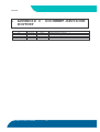
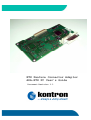
ETX Feature Connector Adaptor
ADA-ETX FC User’s Guide
Document Revision 1.1
Kontron
CONTENTS
1. USER INFORMATION ............................................2
1.1 About This Manual ........................................2
1.2 Copyright Notice .........................................2
1.3 Trademarks ...............................................2
1.4 Standards ................................................3
1.5 Warranty .................................................3
Technical Support ............................................3
2. INTRODUCTIONS ...............................................5
2.1 ADA-ETX FC3 ..............................................5
3. SPECIFICATION ...............................................6
3.1 ADA-ETX FC3 with Texas Instruments TFP410 ................6
3.2 Mechanical Specifications ................................7
3.2.1. Dimensions ............................................7
3.3 Electrical Specifications ................................8
3.3.1. Supply Voltage ........................................8
3.3.2. Supply Voltage Ripple .................................8
3.3.3. Supply Current ........................................8
3.4 Environmental Specifications .............................8
3.4.1. Temperature ...........................................8
3.4.2. Humidity ..............................................8
4. APPENDIX A: BLOCK DIAGRAM ...................................9
5. APPENDIX B: CONNECTOR PINNOUT ..............................10
5.1 Connector Locations .....................................10
5.2 Feature Connector X1 Pinout ADA-ETX FC3 .................11
5.3 DVI Connector X2 Pinout on ADA-ETX FC3 ..................12
6. APPENDIX C: DOCUMENT-REVISION HISTORY ......................13
ADA-ETX FC User’s Guide
1
Kontron
1.
USER INFORMATION
1.1
About This Manual
This document provides information about products from
Kontron Embedded Computers AG and/or its subsidiaries. No
warranty of suitability, purpose, or fitness is implied.
While every attempt has been made to ensure that the
information in this document is accurate, the information
contained within is supplied “ as-is ” and is subject to
change without notice.
For the circuits, descriptions and tables indicated, Kontron
assumes no responsibility as far as patents or other rights
of third parties are concerned.
1.2
Copyright Notice
Copyright © 2003 Kontron Embedded Computers AG.
All rights reserved. No part of this manual may be
reproduced, transmitted, transcribed, stored in a retrieval
system, or translated into any language or computer
language, in any form or by any means (electronic,
mechanical, photocopying, recording, or otherwise), without
the express written permission of Kontron.
JUMPtec Industrielle Computertechnik AG and Kontron Embedded
Computers AG merged in July 2002. JUMPtec is now known as
Kontron Embedded Modules GmbH. Products labeled and sold
under the Kontron Embedded Modules name (formerly JUMPtec)
are now considered Kontron products for all practical
purposes, including warranty and support.
DIMM-PC®, PISA®, ETX Components SBC, JUMPtec®, and Kontron
Embedded Modules are registered trademarks of Kontron
Embedded Modules GmbH©.
1.3
Trademarks
The following lists the trademarks of components used in
this board.
IBM, XT, AT, PS/2 and Personal System/2 are trademarks of
International Business Machines Corp.
Microsoft is a registered trademark of Microsoft Corp.
ADA-ETX FC User’s Guide
2
Kontron
Intel is a registered trademark of Intel Corp.
All other products and trademarks mentioned in this
manual are trademarks of their respective owners.
1.4
Standards
Kontron Embedded Modules is certified to ISO 9000 standards.
1.5
Warranty
This Kontron Embedded Modules product is warranted against
defects in material and workmanship for the warranty period
from the date of shipment. During the warranty period,
Kontron Embedded Modules will at its discretion decide to
repair or replace defective products.
Within the warranty period, the repair of products is free
of charge as long as warranty conditions are observed.
The warranty does not apply to defects resulting from
improper or inadequate maintenance or handling by the buyer,
unauthorized modification or misuse, operation outside of
the product’s environmental specifications or improper
installation or maintenance.
Kontron Embedded Modules will not be responsible for any
defects or damages to other products not supplied by Kontron
Embedded Modules that are caused by a faulty Kontron
Embedded Modules product.
Technical Support
Technicians and engineers from Kontron Embedded Modules
and/or its subsidiaries are available for technical support.
We are committed to making our product easy to use and will
help you use our products in your systems.
Before contacting Kontron Embedded Modules technical
support, please consult our Web site at http://www.kontronem.com/index-en.html for the latest product documentation,
utilities, and drivers. If the information does not help
solve the problem, contact us by telephone.
Asia
Europe
North/South America
Kontron Asia
Kontron Embedded Modules
Kontron America
ADA-ETX FC User’s Guide
3
Kontron
5F-1, 341, Sec 4
Chung Hsiao E. Road
Taipei, Taiwan
Brunnwiesenstr. 16
94469 Deggendorf – Germany
3988 Trust Way
Hayward, CA 94545
Tel: +886 2 2751 7192
Tel: +49 (0) 991-37024-0
Tel: +1 (510)-732-6900
Fax: +886 2 2772 0314
Fax: +49 (0) 991-37024-109
Fax: +1 (510)-732-7655
ADA-ETX FC User’s Guide
4
Kontron
2.
INTRODUCTIONS
2.1
ADA-ETX FC3
The ADA-ETX FC3 is a small adaptor board to convert the
signals from DVO to DVI. The DVO signals are available on
Kontron boards which has implemented the “ feature
connector ” ´.
The ADA-ETX FC3 is supported by the following Board:
ETX PM
ADA-ETX FC User’s Guide
5
Kontron
SPECIFICATION
3.
3.1
ADA-ETX FC3 with Texas Instruments
TFP410
-
The ADA-ETX FC3 supports DVI resolutions from VGA to
SXGA@60Hz
-
Programmable by Using the I2C Serial Interface
-
To activate the ADA-ETX FC3 please enable in the Phoenix
Bios Setup:
-> Advanced -> Display Control :
CRT+EFP
ADA-ETX FC User’s Guide
6
EFP Only
or
Kontron
3.2
Mechanical Specifications
3.2.1.
Dimensions
63.0 mm x 106.0 mm (2.2 ” x 4.17 ” )
Height (total) approx. 15 mm(0.6 ” )
ADA-ETX FC User’s Guide
7
Kontron
3.3
Electrical Specifications
3.3.1.
Supply Voltage
5V DC +/- 5%
5V rise time from <10% to nominal within 0.1 ms to 20 ms
3.3.2.
Supply Voltage Ripple
Maximum 100 mV peak to peak 0 – 20 MHz
3.3.3.
Supply Current
Power-consumption tests were executed during different
applications conducted.
3.4
Environmental Specifications
3.4.1.
Temperature
Operating:
•
Ambient temperature: 0 to +60 °C
Non-operating: -40 to +85 °C
3.4.2.
Humidity
Operating: 10% to 90% (non condensing)
Non operating: 5% to 95% (non condensing)
ADA-ETX FC User’s Guide
8
Kontron
4.
APPENDIX A: BLOCK DIAGRAM
Feature Connector
X1
1.5V
Regulator
(LDO)
1.5V
I2C
Levelshifter
5V
3.3V
Regulator
(LDO)
12bit DVO (Port B)
3.3V
Texas Instruments
TFP 410
DVI
X2
ADA-ETX FC User’s Guide
9
Kontron
5.
APPENDIX B: CONNECTOR PINNOUT
5.1
Connector Locations
ADA-ETX FC User’s Guide
10
Kontron
Feature Connector X1 Pinout ADA-ETX FC3
5.2
Pin
1
2
3
4
5
6
7
8
9
10
11
12
13
14
15
16
17
18
19
20
21
22
23
24
25
26
27
28
29
30
31
32
33
34
35
36
37
38
39
40
41
42
43
44
45
46
47
48
49
50
Pin on ETX-PM
DVOC_D0
DVOB_D0
DVOC_D1
VCC
DVOB_D1
DVOC_D2
DVOB_D2
VCC
DVOC_D3
DVOB_D3
DVOC_D4
GND
DVOB_D4
DVOC_D5
DVOB_D5
GND
DVOC_D6
DVOB_D6
DVOC_D7
GND
DVOB_D7
DVOC_D8
DVOB_D8
GND
DVOC_D9
DVOB_D9
DVOC_D10
GND
DVOB_D10
DVOC_D11
DVOB_D11
GND
DVOB_CLK
DVOB_CLK#
GND
DVOC_CLK
DVOC_CLK#
GND
DVOB_VSYNC
DVOB_HSYNC
DVOB_BLANK#
NC
DVOC_VSYNC
DVOC_HSYNC
DVOC_BLANK#
DVOC_FLDSTL
NC
MI2CDATA
MI2CCLK
GVREF
ADA-ETX FC User’s Guide
Description
DVOC Data D0
DVOB Data D0
DVOC Data D1
Supply +5V
DVOB Data D1
DVOC Data D2
DVOB Data D2
Supply +5V
DVOC Data D3
DVOB Data D3
DVOC Data D4
Ground
DVOB Data D4
DVOC Data D5
DVOB Data D5
Ground
DVOC Data D6
DVOB Data D6
DVOC Data D7
Ground
DVOB Data D7
DVOC Data D8
DVOB Data D8
Ground
DVOC Data D9
DVOB Data D9
DVOC Data D10
Ground
DVOB Data D10
DVOC Data D11
DVOB Data D11
Ground
Differential DVO Clock Output
Differential DVO Clock Output
Ground
Differential DVO Clock Output
Differential DVO Clock Output
Ground
VSYNC signal for the DVOB interface
HSYNC signal for the DVOB interface
Flicker Blank or Border Period Indication for DVOB
Not supported now.
VSYNC signal for the DVOC interface
HSYNC signal for the DVOC interface
Flicker Blank or Border Period Indication for DVOC
TV Field and Flat Panel Stall Signal for DVOC
Not supported now.
DVO I2C Clock
DVO I2C Data
Input buffer VREF
11
not used
not used
not used
not used
not used
not used
not used
not used
not used
not used
not used
not used
not used
not used
not used
not used
not used
not used
Kontron
5.3
DVI Connector X2 Pinout on ADA-ETX FC3
Pin
Name
Pin
Name
1
2
3
TMDS Data2TMDS Data2+
GND
13
14
15
Not connected
+5 V Power
GND
4
5
6
Not connected
Not connected
DDC Clock [SCL]
16
17
18
Hot Plug Detect
TMDS Data0TMDSData0+
7
8
9
DDC Data [SDA]
Not connected
TMDS Data1-
19
20
21
GND
Not connected
Not connected
10
11
12
TMDS Data1+
GND
Not connected
22
23
24
GND
TMDS Clock +
TMDS Clock -
C1
C2
C3
Not connected
Not connected
Not connected
C4
C5
Not connected
GND
Legend:
DDC = Display Data Channel
T.M.D.S. = Transition Minimized Differential Signal
Please refer to following link for detailed information
about DVI specification: http://www.ddwg.org
On VCC pins: To protect the external powerlines of peripheral devices the customer has to take care about:
that the wires have the right diameter to withstand the maximum available current
that the enclosure of the peripheral device fulfils the fire protecting requirements of IEC/EN 60950.
ADA-ETX FC User’s Guide
12
Kontron
6.
APPENDIX C: DOCUMENT-REVISION
HISTORY
Revision
Date
Edited by
0.1
0.2
1.0
1.1
02.11.04
03.07.05
24.07.05
05.12.05
HMA
TJO
TJO
TJO
ADA-ETX FC User’s Guide
Changes
Created preliminary manual.
Added new drawings
First public release
Layout reworked
13