1
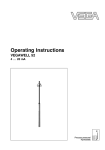
Operating Instructions
Submersible pressure transmitter with
ceramic measuring cell
VEGAWELL 52
4 … 20 mA/HART Pt 100
Document ID: 35402
Contents
Contents
1
About this document
1.1 Function ........................................................................................................................... 4
1.2 Target group ..................................................................................................................... 4
1.3 Symbols used................................................................................................................... 4
2
For your safety
2.1 Authorised personnel ....................................................................................................... 5
2.2 Appropriate use ................................................................................................................ 5
2.3 Warning about incorrect use............................................................................................. 5
2.4 General safety instructions ............................................................................................... 5
2.5 Safety label on the instrument .......................................................................................... 6
2.6 CE conformity................................................................................................................... 6
2.7 NAMUR recommendations .............................................................................................. 6
2.8 Safety instructions for Ex areas ........................................................................................ 6
2.9 Environmental instructions ............................................................................................... 6
3
Product description
3.1 Configuration .................................................................................................................... 7
3.2 Principle of operation........................................................................................................ 8
3.3 Operation ......................................................................................................................... 9
3.4 Packaging, transport and storage ..................................................................................... 9
3.5 Accessories and replacement parts ............................................................................... 10
4
Mounting
4.1 General instructions ....................................................................................................... 12
4.2 Mounting steps with straining clamp............................................................................... 13
4.3 Mounting steps with screwed connection ....................................................................... 14
4.4 Mounting steps with threaded connection or housing .................................................... 15
5
Connecting to power supply
5.1 Preparing the connection ............................................................................................... 16
5.2 Connection procedure .................................................................................................... 18
5.3 Wiring plan ..................................................................................................................... 18
5.4 Switch-on phase............................................................................................................. 20
6
Set up with VEGADIS 82
6.1 Principle of operation and connection ............................................................................ 22
6.2 Adjustment volume ......................................................................................................... 22
6.3 Setup steps .................................................................................................................... 23
7
Setup with PACTware
7.1 Connect the PC .............................................................................................................. 24
7.2 Parameter adjustment with PACTware ............................................................................ 25
7.3 Saving the parameter adjustment data ........................................................................... 26
9
2
Dismount
VEGAWELL 52 • 4 … 20 mA/HART Pt 100
35402-EN-140801
8 Maintenanceandfaultrectification
8.1 Maintenance .................................................................................................................. 27
8.2 Rectify faults ................................................................................................................... 27
8.3 Shorten suspension cable .............................................................................................. 28
8.4 Shorten suspension cable - Version with housing .......................................................... 28
8.5 How to proceed if a repair is needed .............................................................................. 30
Contents
9.1
9.2
Dismounting steps.......................................................................................................... 31
Disposal ......................................................................................................................... 31
35402-EN-140801
10 Supplement
10.1 Technical data ................................................................................................................ 32
10.2 Dimensions .................................................................................................................... 38
Supplementary documentation
Information:
Supplementary documents appropriate to the ordered version come
withthedelivery.Youcanfindthemlistedinchapter"Product description".
Editing status:2014-07-07
VEGAWELL 52 • 4 … 20 mA/HART Pt 100
3
1 About this document
1
About this document
1.1
Function
1.2
Target group
1.3
Symbols used
This operating instructions manual provides all the information you
need for mounting, connection and setup as well as important instructionsformaintenanceandfaultrectification.Pleasereadthisinformation before putting the instrument into operation and keep this manual
accessible in the immediate vicinity of the device.
This operating instructions manual is directed to trained specialist
personnel. The contents of this manual should be made available to
these personnel and put into practice by them.
Information, tip, note
This symbol indicates helpful additional information.
Caution: If this warning is ignored, faults or malfunctions can result.
Warning: If this warning is ignored, injury to persons and/or serious
damage to the instrument can result.
Danger: If this warning is ignored, serious injury to persons and/or
destruction of the instrument can result.
Ex applications
This symbol indicates special instructions for Ex applications.
•
→
1
SIL applications
This symbol indicates instructions for functional safety which must be
taken into account particularly for safety-relevant applications.
List
The dot set in front indicates a list with no implied sequence.
Action
This arrow indicates a single action.
Sequence of actions
Numbers set in front indicate successive steps in a procedure.
Battery disposal
This symbol indicates special information about the disposal of batteries and accumulators.
35402-EN-140801
4
VEGAWELL 52 • 4 … 20 mA/HART Pt 100
2 For your safety
2
2.1
For your safety
Authorised personnel
All operations described in this operating instructions manual must
be carried out only by trained specialist personnel authorised by the
plant operator.
During work on and with the device the required personal protective
equipment must always be worn.
2.2
Appropriate use
Model VEGAWELL 52 is a pressure transmitter for level and gauge
measurement.
Youcanfinddetailedinformationabouttheareaofapplicationin
chapter"Product description".
Operational reliability is ensured only if the instrument is properly
usedaccordingtothespecificationsintheoperatinginstructions
manual as well as possible supplementary instructions.
For safety and warranty reasons, any invasive work on the device
beyond that described in the operating instructions manual may be
carried out only by personnel authorised by the manufacturer. Arbitraryconversionsormodificationsareexplicitlyforbidden.
2.3
Warning about incorrect use
2.4
General safety instructions
Inappropriate or incorrect use of the instrument can give rise to
application-specifichazards,e.g.vesseloverfillordamagetosystem
components through incorrect mounting or adjustment.
This is a state-of-the-art instrument complying with all prevailing
regulations and guidelines. The instrument must only be operated in a
technicallyflawlessandreliablecondition.Theoperatorisresponsible
for the trouble-free operation of the instrument.
During the entire duration of use, the user is obliged to determine the
compliance of the necessary occupational safety measures with the
current valid rules and regulations and also take note of new regulations.
35402-EN-140801
The safety instructions in this operating instructions manual, the national installation standards as well as the valid safety regulations and
accident prevention rules must be observed by the user.
For safety and warranty reasons, any invasive work on the device
beyond that described in the operating instructions manual may be
carried out only by personnel authorised by the manufacturer. Arbitraryconversionsormodificationsareexplicitlyforbidden.
The safety approval markings and safety tips on the device must also
be observed.
VEGAWELL 52 • 4 … 20 mA/HART Pt 100
5
2 For your safety
2.5
Safety label on the instrument
2.6
CE conformity
2.7
NAMUR recommendations
The safety approval markings and safety tips on the device must be
observed.
ThisdevicefulfillsthelegalrequirementsoftheapplicableECguidelines.ByattachingtheCEmark,VEGAprovidesaconfirmationof
successfultesting.YoucanfindtheCEconformitydeclarationinthe
downloadareaof"www.vega.com".
NAMUR is a user association for automation technology in the
processindustriesinGermany.Severalofitskeyactivitiesaredefining standards as well as setting user requirements on new devices,
systems and technologies. The published NAMUR recommendations
(NE)areacceptedasthestandardinfieldinstrumentation.
ThedevicefulfillstherequirementsofthefollowingNAMURrecommendations:
•
•
•
NE 21 – Electromagnetic compatibility of equipment
NE 43 – Signal level for malfunction information from measuring
transducers
NE53–Compatibilityoffielddevicesanddisplay/adjustment
components
2.8
Safety instructions for Ex areas
2.9
Environmental instructions
PleasenotetheEx-specificsafetyinformationforinstallationandoperation in Ex areas. These safety instructions are part of the operating
instructions manual and come with the Ex-approved instruments.
Protection of the environment is one of our most important duties.
That is why we have introduced an environment management system
with the goal of continuously improving company environmental protection.Theenvironmentmanagementsystemiscertifiedaccording
to DIN EN ISO 14001.
Pleasehelpusfulfillthisobligationbyobservingtheenvironmental
instructions in this manual:
•
•
Chapter"Packaging, transport and storage"
Chapter"Disposal"
35402-EN-140801
6
VEGAWELL 52 • 4 … 20 mA/HART Pt 100
3 Product description
3
Scope of delivery
3.1 Configuration
The scope of delivery encompasses:
•
•
•
Constituent parts
Product description
VEGAWELL 52 pressure transmitter with suspension cable
optionally available with straining clamp, screwed connection or
housing with cable locking
Documentation
– this operating instructions manual
– Testcertificate
– Supplementaryinstructions"Suitable for drinking water"
(optional)
– Ex-specific"Safety instructions"(withExversions)
– ifnecessary,furthercertificates
VEGAWELL 52 with suspension cable consists of the following
components:
•
•
•
Transmitter
Suspension cable
Optionalfasteningelementorhousingwiththreadedfitting
Thecomponentsareavailableindifferentversions.
2
1
Fig. 1: Example of a VEGAWELL 52 with transmitter 22 mm
35402-EN-140801
1
2
Type label
Transmitter
Suspension cable
Thetypelabelcontainsthemostimportantdataforidentificationand
use of the instrument:
VEGAWELL 52 • 4 … 20 mA/HART Pt 100
7
3 Product description
1
2
3
4
5
6
7
8
9
14
13
12
10
11
Fig. 2: Structure type label VEGAWELL 52 (example)
1
2
3
4
5
6
7
8
9
10
11
12
13
14
Serial number - Instrument search
Instrument type
Product code
Approvals
Process temperature
Signal output/Operating voltage
Materials Transmitter/Measuring cell/Measuring cell seal/Suspension cable
Measuring range
Cable length
Order number
Protection rating
Serial number of the instrument
Assignment suspension cable, temperature
ID numbers, instrument documentation
Assignment suspension cable, level
The type label contains the serial number of the instrument. With it
youcanfindthefollowinginstrumentdataonourhomepage:
•
•
•
•
•
Product code (HTML)
Delivery date (HTML)
Order-specificinstrumentfeatures(HTML)
Operating instructions at the time of shipment (PDF)
Testcertificate(PDF)-optional
Go to www.vega.com,"VEGA Tools"and"Instrument search".Enter
the serial number.
Alternatively, you can access the data via your smartphone:
•
•
•
8
3.2
Principle of operation
Model VEGAWELL 52 is suitable for continuous level measurement of
liquids. Typical applications are measurements in water/waste water
facilities, deep wells and in the shipbuilding industry.
VEGAWELL 52 • 4 … 20 mA/HART Pt 100
35402-EN-140801
Application area
Downloadthesmartphoneapp"VEGA Tools"fromthe"Apple App
Store"orthe"Google Play Store"
Scan the Data Matrix code on the type label of the instrument or
Enter the serial number manually in the app
3 Product description
Functional principle
The actual sensor element is the CERTEC® measuring cell with rugged ceramic diaphragm. The hydrostatic pressure causes a capacitance change in the measuring cell via the ceramic diaphragm. This
change is converted into an appropriate output signal.
The CERTEC® measuring cell is also equipped with a temperature
sensor Pt 100 in four-wire technology. The resistance value is accessed via the wires of the suspension cable. The power supply or the
processing is carried out via an external temperature transducer.
Seal concept
As a standard feature, the CERTEC® measuring cell is equipped with
a lateral, recessed seal.
Instruments with double seal have an additional front seal.
1
2
3
4
5
Fig. 3: Front-flush installation of the CERTEC® measuring cell with double seal
1
2
3
4
5
Voltage supply
Housing, transmitter
Measuring cell
Lateral seal for measuring cell
Additional, front seal for measuring cell
Diaphragm
4 … 20 mA/HART two-wire electronics for voltage supply and measured value transmission on the same cable.
Thedataforpowersupplyarespecifiedinchapter"Technical data".
3.3
Operation
The instrument can be adjusted with the following adjustment media:
•
•
•
With the external display and adjustment instrument VEGADIS 82
an adjustment software according to FDT/DTM standard, e.g.
PACTware and PC
With a HART handheld
35402-EN-140801
The type of adjustment and the adjustment options depend on the
selected adjustment component. The entered parameters are generally saved in the respective sensor, when adjusting with PACTware™
and PC optionally also in the PC.
Packaging
3.4
Packaging, transport and storage
Your instrument was protected by packaging during transport. Its
capacity to handle normal loads during transport is assured by a test
based on ISO 4180.
VEGAWELL 52 • 4 … 20 mA/HART Pt 100
9
3 Product description
The packaging of standard instruments consists of environmentfriendly, recyclable cardboard. For special versions, PE foam or PE
foil is also used. Dispose of the packaging material via specialised
recycling companies.
Transport
Transport must be carried out in due consideration of the notes on the
transport packaging. Nonobservance of these instructions can cause
damage to the device.
Transport inspection
The delivery must be checked for completeness and possible transit
damage immediately at receipt. Ascertained transit damage or concealed defects must be appropriately dealt with.
Storage
Up to the time of installation, the packages must be left closed and
stored according to the orientation and storage markings on the
outside.
Unless otherwise indicated, the packages must be stored only under
the following conditions:
Storage and transport
temperature
VEGABOX 03
•
•
•
•
•
•
•
Not in the open
Dry and dust free
Not exposed to corrosive media
Protected against solar radiation
Avoiding mechanical shock and vibration
Storageandtransporttemperatureseechapter"Supplement Technical data - Ambient conditions"
Relative humidity 20 … 85 %
3.5
Accessories and replacement parts
The VEGABOX 03 is a breather housing for VEGAWELL 52. The
housingcontainsafilterelementforventilation.
Youcanfindfurtherinformationintheoperatinginstructions"Breather
housing with ventilation filter"(Document-ID45925).
Interface adapter
The interface adapter VEGACONNECT 4 enables the connection of
communication-capable instruments to the USB interface of a PC. For
parameter adjustment of these instruments, an adjustment software
such as PACTware with VEGA-DTM is required.
Youcanfindfurtherinformationintheoperatinginstructions"Interface
adapter VEGACONNECT"(Document-ID32628).
VEGADIS 82
VEGADIS 82 is suitable for measured value indication and adjustment
of sensors with HART protocol. It is looped into the 4 … 20 mA/HART
signal cable.
Measuring instrument
holder
10
The measuring instrument holder is used for wall/tube mounting of
VEGABAR series 80 pressure transmitters and VEGAWELL 52 submersible pressure transmitters. Supplied reducers enable the adaptationtodifferentinstrumentdiameters.Thematerialusedis316L.
VEGAWELL 52 • 4 … 20 mA/HART Pt 100
35402-EN-140801
Youcanfindfurtherinformationintheoperatinginstructions"VEGADIS 82"(Document-ID45300).
3 Product description
Youcanfindadditionalinformationintheoperatinginstructions
"Mounting accessory pressure"(Document-ID43478).
The robust, heavy-duty bracket of 1.4301/304 is designed for wall
mounting VEGA instruments. The required fastening elements are
included in the shipment.
35402-EN-140801
Mounting bracket
VEGAWELL 52 • 4 … 20 mA/HART Pt 100
11
4 Mounting
4
4.1
Mounting
General instructions
Suitability for the process Make sure that all parts of the instrument coming in direct contact
conditions
with the process, especially the sensor element, process seal and
processfitting,aresuitablefortheexistingprocessconditions,such
as process pressure, process temperature as well as the chemical
properties of the medium.
Youcanfindthespecificationsinchapter"Technical data"andonthe
nameplate.
Installation position
Lateral movements of the transmitter can cause measurement errors.
For this reason, mount the instrument in a calm area or in a suitable
protective tube.
Pressure compensation
The suspension cable has a capillary for atmospheric pressure compensation. Therefore lead the cable end into a dry environment or a
suitable terminal housing, for example VEGABOX 03 or VEGADIS 82.
Mounting example
Fig. 4: Mounting example: VEGAWELL 52 in an open basin with breather housing VEGABOX 03
35402-EN-140801
12
VEGAWELL 52 • 4 … 20 mA/HART Pt 100
4 Mounting
4.2
Mounting steps with straining clamp
1
2
3
Fig. 5: Straining clamp
1
2
3
Suspension cable
Suspension opening
Clamping jaws
Mount VEGAWELL 52 with straining clamp as follows:
1. Hang the straining clamp on a suitable wall hook
2. Lower VEGAWELL 52 to the requested height
3. Slide the clamping jaws upward and push the suspension cable
between them
4. Hold the suspension cable, push the clamping jaws downward
andfixthemwithalightblow
35402-EN-140801
Disassembly is carried out in reverse order.
VEGAWELL 52 • 4 … 20 mA/HART Pt 100
13
4 Mounting
4.3
Mounting steps with screwed connection
1
2
3
4
5
6
Fig. 6: Threaded fitting
1
2
3
4
5
6
Suspension cable
Sealing screw
Cone bushing
Seal cone
Threaded fitting
Seal
Mount VEGAWELL 52 with screwed connection as follows:
1. Weld the welded socket into the vessel top
2. Lower VEGAWELL 52 to the requested height by means on the
welded socket G1½ or 1½ NPT on the vessel side
3. Shift the suspension cable from below through the opened
threadedfitting
4. Slide the sealing cone and the cone sleeve over the suspension
cable, fasten manually with the seal screw
5. Screw the screwed connection into the socket, tighten with
SW 30 and then tighten seal screw with SW 19
How to correct the height:
1. Loosen seal screw with SW 19
2. Slide seal cone and cone sleeve to the requested position on the
cable
3. Fasten the seal screw
Disassembly is carried out in reverse order.
35402-EN-140801
14
VEGAWELL 52 • 4 … 20 mA/HART Pt 100
4 Mounting
4.4
Mounting steps with threaded connection or
housing
1
2
3
Fig. 7: Plastic housing
1
2
3
Mount into the vessel
Housing
Seal
Thread
Mount VEGAWELL 52 as follows:
1. Weld the welded socket G1½ A or 1½ NPT to the vessel top
2. Shift transmitter through the mounting boss
3. Turn the thread with seal into the socket and tighten with SW 461)
Disassembly is carried out in reverse order.
Mounting into the basin
Mount VEGAWELL 52 as follows:
1. Fasten the mounting bracket at the suitable height on the basin
wall
2. Lead the transmitter through the opening of the mounting bracket
and the counter nut
35402-EN-140801
3. Fasten counter nut with SW 46 on the thread
1)
Seal with resistant material with thread 1½ NPT.
VEGAWELL 52 • 4 … 20 mA/HART Pt 100
15
5 Connecting to power supply
5
Safety instructions
Connecting to power supply
5.1
Preparing the connection
Generally connect the instrument only in the complete absence of line
voltage.
The instrument is equipped with an integrated overvoltage protection.
For additional protection of the signal circuit, we recommend further
external overvoltage arresters.
Take note of safety
instructions for Ex
applications
Select power supply
•
•
Type B63-48 (use with VEGAWELL 52 with plastic housing) or
Type ÜSB 62-36G.X (use in a separate housing)
Inhazardousareasyoumusttakenoteoftherespectiveregulations,
conformityandtypeapprovalcertificatesofthesensorsandpower
supply units.
Power supply and current signal are carried on the same two-wire
cable.Thevoltagesupplyrangecandifferdependingontheinstrument version.
Thedataforpowersupplyarespecifiedinchapter"Technical data".
Provide a reliable separation between the supply circuit and the
mains circuits according to DIN EN 61140 VDE 0140-1.
VEGA power supply units VEGATRENN 149AEx, VEGASTAB 690,
VEGADIS 371 as well as all VEGAMETs meet this requirement. When
using one of these instruments, protection class III is ensured for
VEGAWELL 52.
Keepinmindthefollowingadditionalfactorsthatinfluencetheoperating voltage:
•
•
Select installation cable
Output voltage of the power supply unit can be lower under nominal load (with a sensor current of 20.5 mA or 22 mA in case of fault
message)
Influenceofadditionalinstrumentsinthecircuit(seeloadvaluesin
chapter"Technical data")
The instrument is connected with standard two-wire installation cable
without screen. If electromagnetic interference is expected which
is above the test values of EN 61326 for industrial areas, screened
cable should be used.
Use cable with round cross-section. A cable outer diameter of
5…9mm(0.2…0.35in)ensuresthesealeffectofthecablegland.
Ifyouareusingcablewithadifferentdiameterorcross-section,
exchange the seal or use a suitable cable gland.
We generally recommend the use of screened cable for HART multidrop mode.
35402-EN-140801
16
VEGAWELL 52 • 4 … 20 mA/HART Pt 100
5 Connecting to power supply
1
2
3
Fig. 8: Connect VEGAWELL 52 to power supply
1
2
3
Cable screening and
grounding
Direct connection
Connection via VEGABOX 03
Connection via housing
If screened cable is required, we recommend connecting the cable
screen on both ends to ground potential. In the connection housing of
the sensor or in VEGABOX 03, the screen must be connected directly
to the internal ground terminal. The ground terminal on the outside of
the housing must be connected to the ground potential (low impedance).
In Ex systems, the grounding is carried out according to the installation regulations.
35402-EN-140801
In electroplating and CCP systems (cathodic corrosion protection) it
mustbetakenintoaccountthatsignificantpotentialdifferencesexist.
This can lead to unacceptably high currents in the cable screen if it is
grounded at both ends.
Information:
Themetallicpartsoftheinstrument(processfitting,transmitter,concentric tube, etc.) are conductively connected with the inner and outer
ground terminal on the housing. This connection exists either directly
via connecting metallic parts or, in case of instruments with external
electronics, via the screen of the special connection cable.
Youcanfindspecificationsonthepotentialconnectionsinsidethe
instrumentinchapter"Technical data".
VEGAWELL 52 • 4 … 20 mA/HART Pt 100
17
5 Connecting to power supply
Direct connection
5.2
Connection procedure
Proceed as follows:
1. Wire the suspension cable up to the connection compartment2)
2. Connect the wire ends to the screw terminals according to the
wiring plan
Connection via VEGABOX 03
Connect the VEGAWELL 52 according to the description in the operating instructions of VEGABOX 03.
Connection via housing
Proceed as follows:
1. Unscrew the housing cover
2. Insert the installation cable through the cable entry into the plastic
housing
3. Loosen the screws with a screwdriver
4. Insert the wire ends into the open terminals according to the wiring plan
5. Tighten the screws with a screwdriver
6. Check the hold of the wires in the terminals by lightly pulling on
them
7. Tighten the compression nut of the cable entry gland. The seal
ring must completely encircle the cable
8. Retighten the housing cover
Theelectricalconnectionisfinished.
5.3
Wiring plan
Direct connection
8
1
2
3
4
5
6
7
Fig. 9: Wire assignment, suspension cable
1
2
3
4
5
6
7
8
18
The suspension cable is already preconfectioned. After shortening the suspension cable, fasten the type plate with support again to the cable.
VEGAWELL 52 • 4 … 20 mA/HART Pt 100
35402-EN-140801
2)
Brown (+): to power supply or to the processing system
Blue (-): to power supply or to the processing system
White: for processing of the integrated Pt 100 (power supply)
Yellow: for processing of the integrated Pt 100 (measurement)
Red: for processing of the integrated Pt 100 (measurement)
Black: for processing of the integrated Pt 100 (power supply)
Shielding
Breather capillaries with filter element
5 Connecting to power supply
Connection via VEGABOX 03
3
–
+ 2
1
4
Fig. 10: Wiring plan VEGAWELL 52 for 4 … 20 mA/HART Pt 100
1
2
3
To power supply or the processing system (signal pressure transmitter)
To power supply or the processing system (connection cables resistance
thermometer Pt 100)
Shielding3)
Wire number
Wire colour/Polarity
Function
1
brown (+)
Power supply/signal
pressure transmitter
2
blue (-)
Power supply/signal
pressure transmitter
3
White
Power supply Pt 100
4
Yellow
Measurement Pt 100
5
Red
Measurement Pt 100
6
Black
Power supply Pt 100
Shielding
Grounding
Connection via housing
6
1
4
5
2
3
3
1
2
35402-EN-140801
Fig. 11: Wiring plan VEGAWELL 52 for 4 … 20 mA/HART Pt 100
1
2
To power supply or the processing system (signal pressure transmitter)
To the temperature transmitter (connection cables resistance thermometer
3)
Connect screen to ground terminal. Connect ground terminal on the outside
of the housing to ground as prescribed. The two terminals are galvanically
connected.
VEGAWELL 52 • 4 … 20 mA/HART Pt 100
19
5 Connecting to power supply
3
Pt 100)
Shielding4)
Terminal, housing
Wire colour/Polarity
Function
1
brown (+)
Power supply/signal
pressure transmitter
2
blue (-)
Power supply/signal
pressure transmitter
3
White
Power supply Pt 100
4
Yellow
Measurement Pt 100
5
Red
Measurement Pt 100
6
Black
Power supply Pt 100
Shielding
Grounding
Connection via VEGADIS 82
power supply
Sensor
HART
2
R
(+)1
2(-) off on
(+)3
4(-)
3
4
1
Fig. 12: Wiring plan VEGAWELL 52 4 … 20 mA/HART
1
2
3
4
To the sensor
Switch for communication resistor (on = activated, off = deactivated)
Terminal for connection of the cable screen
For power supply
Wire number
Wire colour/Polarity
Terminal VEGADIS 82
1
brown (+)
1
2
blue (-)
2
Shielding
Ground terminal
5.4
Switch-on phase
After connecting VEGAWELL 52 to power supply or after a voltage
recurrence, the instrument carries out a self-check:
•
•
Internal check of the electronics
4 … 20 mA output jumps to the failure signal
4)
20
Connect screen to ground terminal. Connect ground terminal on the outside
of the housing to ground as prescribed. The two terminals are galvanically
connected.
VEGAWELL 52 • 4 … 20 mA/HART Pt 100
35402-EN-140801
Aftertherun-upperiod(specificationsee"Technical data"),theinstrument delivers an output signal of 4 … 20 mA. The value corresponds
5 Connecting to power supply
35402-EN-140801
to the actual level as well as the settings already carried out, e.g.
factory setting.
VEGAWELL 52 • 4 … 20 mA/HART Pt 100
21
6 Set up with VEGADIS 82
6
Set up with VEGADIS 82
6.1
Principle of operation and connection
The VEGADIS 82 is an external display and adjustment unit without
additional external energy.
The instrument is suitable for measured value indication and adjustment of sensors with HART protocol. It can be connected at any point
to the 4 … 20 mA signal cable. A separate external energy is not
required.
=
2
~
3
1
Fig. 13: Connection of the VEGADIS 82 to the sensor, adjustment via the display and adjustment module
1
2
3
Sensor
VEGADIS 82
Voltage supply/Signal output
6.2
Adjustment volume
Main menu: Basic adjustment, Diagnosis, Service, Info
Basic adjustment: Settings, for example on position correction,
adjustment, damping
Diagnosis: Information, for example, on device status and peak value
Service: Reset
22
VEGAWELL 52 • 4 … 20 mA/HART Pt 100
35402-EN-140801
Info: Indication of instrument type and serial number
6 Set up with VEGADIS 82
6.3
Setup steps
35402-EN-140801
YoucanfindadetaileddescriptionofthesetupstepsforVEGAWELL
52intheoperatinginstructionsmanual"VEGADIS 82 - 4 … 20 mA/
HART".
VEGAWELL 52 • 4 … 20 mA/HART Pt 100
23
7 Setup with PACTware
7
Connecting the PC to the
signal cable
Setup with PACTware
7.1
Connect the PC
4
5
3
TWIST
OPEN
LOCK
USB
2
1
Fig. 14: Connection of the PC to VEGABOX 03 or communication resistor
1
2
3
4
5
PC with PACTware
USB interface
VEGACONNECT
Communication resistor 250 Ω
power supply unit
Necessary components:
•
•
•
•
•
VEGAWELL 52
PC with PACTware and suitable VEGA DTM
VEGACONNECT with HART adapter cable
HARTresistanceapprox.250Ω
power supply unit
24
VEGAWELL 52 • 4 … 20 mA/HART Pt 100
35402-EN-140801
Note:
With power supply units with integrated HART resistance (internal
resistanceapprox.250Ω),anadditionalexternalresistanceisnot
necessary (e. g. VEGATRENN 149A, VEGAMET 381/391/624/625,
VEGASCAN 693). In such cases, VEGACONNECT can be connected
parallel to the 4 … 20 mA cable.
7 Setup with PACTware
Prerequisites
7.2
Parameter adjustment with PACTware
For parameter adjustment of the instrument via a Windows PC, the
configurationsoftwarePACTwareandasuitableinstrumentdriver
(DTM) according to FDT standard are required. The latest PACTware
version as well as all available DTMs are compiled in a DTM Collection. The DTMs can also be integrated into other frame applications
according to FDT standard.
Note:
To ensure that all instrument functions are supported, you should
always use the latest DTM Collection. Furthermore, not all described
functionsareincludedinolderfirmwareversions.Youcandownload
the latest instrument software from our homepage. A description of
the update procedure is also available in the Internet.
Further setup steps are described in the operating instructions manual"DTM Collection/PACTware"attachedtoeachDTMCollectionand
which can also be downloaded from the Internet. Detailed descriptions are available in the online help of PACTware and the DTMs.
Fig. 15: Example of a DTM view
35402-EN-140801
Standard/Full version
All device DTMs are available as a free-of-charge standard version
and as a full version that must be purchased. In the standard version,
all functions for complete setup are already included. An assistant for
simpleprojectconfigurationsimplifiestheadjustmentconsiderably.
Saving/printing the project as well as import/export functions are also
part of the standard version.
In the full version there is also an extended print function for complete
project documentation as well as a save function for measured value
and echo curves. In addition, there is a tank calculation program as
well as a multiviewer for display and analysis of the saved measured
value and echo curves.
VEGAWELL 52 • 4 … 20 mA/HART Pt 100
25
7 Setup with PACTware
The standard version is available as a download under
www.vega.com/downloadsand"Software".Thefullversionisavailable on CD from the agency serving you.
7.3
Saving the parameter adjustment data
It is recommended to document or save the parameter adjustment
data. That way they are available for multiple use or service purposes.
The VEGA DTM Collection and PACTware in the licensed, professional version provide suitable tools for systematic project documentation
and storage.
35402-EN-140801
26
VEGAWELL 52 • 4 … 20 mA/HART Pt 100
8Maintenanceandfaultrectification
8 Maintenanceandfaultrectification
Maintenance
8.1
Maintenance
If the instrument is used properly, no special maintenance is required
in normal operation.
Insomeapplications,productbuilduponthediaphragmcaninfluence
the measuring result. Depending on the sensor and application, take
precautions to ensure that heavy buildup, and especially a hardening
thereof, is avoided.
Cleaning
If necessary, clean the diaphragm. Make sure that the materials are
resistantagainstthecleanig,seeresistancelistunder"Service"on
"www.vega.com".
Reaction when malfunctions occur
The operator of the system is responsible for taking suitable measures to rectify faults.
Causes of malfunction
VEGAWELL52offersmaximumreliability.Nevertheless,faultscan
occur during operation. These may be caused by the following, e.g.:
8.2
•
•
•
•
Sensor
Process
Voltage supply
Signal processing
Faultrectification
Thefirstmeasurestobetakenaretochecktheoutputsignalsaswell
as to evaluate the error messages via the display and adjustment
module. The procedure is described below. Further comprehensive
diagnostics can be carried out on a PC with the software PACTware
and the suitable DTM. In many cases, the causes can be determined
andthefaultsrectifiedthisway.
24 hour service hotline
Should these measures not be successful, please call in urgent cases
the VEGA service hotline under the phone no. +49 1805 858550.
Check the 4 … 20 mA
signal
35402-EN-140801
Rectify faults
Thehotlineismanned7daysaweekround-the-clock.Sinceweoffer
this service worldwide, the support is only available in the English
language. The service is free, only standard call charges are incurred.
Connect a multimeter in the suitable measuring range according to
the wiring plan.
Error code
Cause
Rectification
4 … 20 mA
signal not
stable
Levelfluctuations
– Set damping (integration time)
VEGAWELL 52 • 4 … 20 mA/HART Pt 100
No atmospheric pres- – Check the capillariy and cut it clean
sure compensation
– Check the pressure compensation
inthehousingandcleanthefilter
element, if necessary
27
8Maintenanceandfaultrectification
Error code
Cause
Rectification
4 … 20 mA
signal missing
Connection to voltage supply wrong
– Check connection according to
chapter"Connection steps"and
if necessary, correct according to
chapter"Wiring plan"
No power supply
– Check cables for breaks; repair if
necessary
– Check, adapt if necessary
Operating voltage
too low or load resistance too high
Current signal 3.6 mA;
22 mA
Electronics module
– Exchange the instrument or send it
or measuring cell dein for repair
fective
In Ex applications, the regulations for the wiring of intrinsically safe
circuits must be observed.
Reaction after fault rectification
Depending on the reason for the fault and the measures taken, the
stepsdescribedinchapter"Set up"mayhavetobecarriedoutagain.
8.3
Shorten suspension cable
Shorten the suspension cable individually. Proceed as follows:
1. Removethefilteradapterfromthecapillaryline
2. Cut the suspension cable to the requested length with side cutters
Caution:
Donotsqueezethecapillarycable,asthiswillimpairthepressure
compensation. If necessary, rework the capillary with a sharp knife.
3. Removeapprox.10cmofthecablemantle,stripoffapprox.1cm
of insulation from the ends of the wires
4. Insertthefilteradapter
Theworkstepsarefinished.
8.4
Shorten suspension cable - Version with
housing
The suspension cable can be shortened individually. For the version
with plastic or stainless steel housing proceed as follows:
1. Unscrew the housing cover
2. Loosen the screw terminals and remove the wire ends of the
suspension cable out of the screw terminals
Caution:
Seal screw is secured with Loctide pink, mote breakaway torque!
28
VEGAWELL 52 • 4 … 20 mA/HART Pt 100
35402-EN-140801
3. Hold the hexagon on the screwed socket with SW 46 and loosen
with seal screw SW 22
8Maintenanceandfaultrectification
1
2
Fig. 16: Step 4
1
2
SW 46
SW 22
4. Pull the suspension cable out of the screwed socket, remove the
pressure screw, cone sleeve and seal cone from the cable
5. Removethefilteradapterfromthecapillaryline
1
2
3
4
5
6
7
Fig. 17: Configuration of the cable seal
35402-EN-140801
1
2
3
4
5
6
7
Connection cable (up to 6 pieces depending on the version)
Cable screening
Breather capillaries with filter element
Seal cone
Suspension cable
Cone bushing
Sealing screw
6. Cut the suspension cable to the requested length with side cutters
7. Removeapprox.10cmofthecablemantle,stripoffapprox.1cm
ofthewireends,insertthefilteradapter
VEGAWELL 52 • 4 … 20 mA/HART Pt 100
29
8Maintenanceandfaultrectification
8. Shift the seal screw, cone sleeve and seal cone to the suspension
cable and insert the cable into the screwed socket, insert the wire
ends through the cable entry into the mounting plate
Theworkstepsarefinished.
8.5
How to proceed if a repair is needed
Youcanfindarepairformaswellasdetailedinformationonhowto
proceed at www.vega.com/downloadsand"Forms and certificates".
By doing this you help us carry out the repair quickly and without having to call back for needed information.
If a repair is necessary, please proceed as follows:
•
•
•
•
Printandfilloutoneformperinstrument
Clean the instrument and pack it damage-proof
Attach the completed form and, if need be, also a safety data
sheet outside on the packaging
Please contact the agency serving you to get the address for
thereturnshipment.Youcanfindtheagencyonourhomepage
www.vega.com.
35402-EN-140801
30
VEGAWELL 52 • 4 … 20 mA/HART Pt 100
9 Dismount
9
9.1
Dismount
Dismounting steps
Warning:
Before dismounting, be aware of dangerous process conditions such
as e.g. pressure in the vessel or pipeline, high temperatures, corrosive or toxic products etc.
Takenoteofchapters"Mounting"and"Connecting to power supply"
and carry out the listed steps in reverse order.
9.2
Disposal
The instrument consists of materials which can be recycled by specialised recycling companies. We use recyclable materials and have
designed the parts to be easily separable.
WEEE directive 2002/96/EG
This instrument is not subject to the WEEE directive 2002/96/EG and
the respective national laws. Pass the instrument directly on to a specialised recycling company and do not use the municipal collecting
points. These may be used only for privately used products according
to the WEEE directive.
Correctdisposalavoidsnegativeeffectsonhumansandtheenvironment and ensures recycling of useful raw materials.
Materials:seechapter"Technical data"
35402-EN-140801
If you have no way to dispose of the old instrument properly, please
contact us concerning return and disposal.
VEGAWELL 52 • 4 … 20 mA/HART Pt 100
31
10 Supplement
10 Supplement
10.1 Technical data
Materials and weights
Materials, wetted parts
Ʋ Transmitter
Ʋ Protective cap
316L, 1.4462 (Duplex), 1.4462 (Duplex) with PE coating,
PVDF, Titanium
PA, PE
Ʋ Diaphragm
sapphire ceramic® (99.9 % oxide ceramic)
Ʋ Measuring cell seal - single
FKM (VP2/A) - FDA and KTW approved, FFKM (Perlast
G75S),FFKM(Kalrez6375),EPDM(A+P75.5/KW75F)
Ʋ Joining material diaphragm/Basic ele- Glass solder
ment measuring cell
Ʋ Measuring cell seal - double
Ʋ Suspension cable
Ʋ Cable gland on the transmitter
FKM (VP2/A)+FKM (VP2/A), FFKM (Perlast
G75S)+FKM(V75J),FFKM(Kalrez6375)+FFKM
(Kalrez6375),EPDM(A+P75.5/KW75F)+EPDM(A+P
75.5/KW75F)
PE (FDA and KTW-approved), FEP, PUR
316L
Ʋ Cable seal with PE, PUR suspension
cable
FKM
Ʋ Straining clamp
316L
Ʋ Cable seal with FEP suspension cable FEP
Ʋ Unassembled screw connection
Ʋ Threaded connection on the housing
Materials, non-wetted parts
Ʋ Housing
Ʋ Type label support on suspension
cable
Ʋ transport protection net
Weight approx.
Ʋ Basic weight
Ʋ Suspension cable
316L, PVDF
316L
plastic PBT (Polyester), 316L
PE hard
PE
0.8 kg (1.764 lbs)
0.1 kg/m (0.07 lbs/ft)
Ʋ Straining clamp
0.2 kg (0.441 lbs)
Ʋ Plastic housing
0.8 kg (1.764 lbs)
Ʋ Threadedfitting
Ʋ Stainless steel housing
0.4 kg (0.882 lbs)
1.6 kg (3.528 lbs)
Adjustment range of the min./max. adjustment relating to the nominal measuring range:
Ʋ Percentage value
Ʋ Pressure value
32
-10 … 110 %
-20 … 120 %
VEGAWELL 52 • 4 … 20 mA/HART Pt 100
35402-EN-140801
Input variable
Adjustment
10 Supplement
Recommended max. turn down
10 : 1 (no limitation)
Nominal measuring ranges and overload capability in bar/kPa
Thespecificationsareonlyanoverviewandrefertothemeasuringcell.Limitationsduetothematerialandversionoftheprocessfittingarepossible.Thespecificationsonthenameplateapply.
Nominal range
Overload capacity, max.
pressure
Overload capacity, min.
pressure
15 bar/1500 kPa
-0.2 bar/-20 kPa
Gauge pressure
0 … 0.1 bar/0 … 10 kPa
0 … 0.2 bar/0 … 20 kPa
20 bar/2000 kPa
-0.4 bar/-40 kPa
0 … 0.4 bar/0 … 40 kPa
30 bar/3000 kPa
-0.8 bar/-80 kPa
0 … 1 bar/0 … 100 kPa
35 bar/3500 kPa
-1 bar/-100 kPa
0 … 2.5 bar/0 … 250 kPa
50 bar/5000 kPa
-1 bar/-100 kPa
0 … 5 bar/0 … 500 kPa
65 bar/6500 kPa
-1 bar/-100 kPa
0 … 10 bar/0 … 1000 kPa
90 bar/9000 kPa
-1 bar/-100 kPa
0 … 25 bar/0 … 2500 kPa
130 bar/13000 kPa
-1 bar/-100 kPa
Absolute pressure
0 … 1 bar/0 … 100 kPa
35 bar/3500 kPa
0 bar abs.
0 … 2.5 bar/0 … 250 kPa
50 bar/5000 kPa
0 bar abs.
0 … 5 bar/0 … 500 kPa
65 bar/6500 kPa
0 bar abs.
0 … 10 bar/0 … 1000 kPa
90 bar/9000 kPa
0 bar abs.
0 … 25 bar/0 … 2500 kPa
130 bar/13000 kPa
0 bar abs.
Nominal measuring ranges and overload capacity in psi
Thespecificationsareonlyanoverviewandrefertothemeasuringcell.Limitationsduetothematerialandversionoftheprocessfittingarepossible.Thespecificationsonthenameplateapply.
Nominal range
Overload capacity, max.
pressure
Overload capacity, min.
pressure
200 psig
-3 psig
Gauge pressure
35402-EN-140801
0 … 1.5 psig
0 … 3 psig
290 psig
-6 psig
0 … 6 psig
430 psig
-12 psig
0 … 15 psig
500 psig
-15 psig
0 … 35 psig
700 psig
-15 psig
0 … 70 psig
950 psig
-15 psig
0 … 150 psig
1300 psig
-15 psig
0 … 350 psig
1900 psig
-15 psig
0 … 900 psig
2900 psig
-15 psig
Absolute pressure
0 … 15 psi
500 psi
0 psi
0 … 35 psi
700 psi
0 psi
VEGAWELL 52 • 4 … 20 mA/HART Pt 100
33
10 Supplement
Nominal range
Overload capacity, max.
pressure
Overload capacity, min.
pressure
0 … 70 psi
900 psi
0 psi
0 … 150 psi
1300 psi
0 psi
0 … 350 psi
1900 psi
0 psi
Output variable
Output signal
4 … 20 mA/HART
HART output values according to HART standard 5.0
Ʋ Primary Value
Ʋ Secondary Value
Signal resolution
Fault signal
Max. output current
Run-up time approx.
Step response time
Pressure
Temperature
1 µA
< 3.6 mA; 20.5 mA; 22 mA; unchanged (adjustable via
PACTware)
22 mA
15 s
≤200ms(ti:0s,0…63%)
Additional output parameter - temperature
Integrated resistance thermometer
Pt 100 according to DIN EN 60751
Tolerance class
B
Adjustment, external temperature transmitter
4 … 20 mA/HART according to -20 … +80 °C
(-4 … +176 °F)
Range
-50 … +100 °C (-58 … +212 °F)
ThedataareanexcerptfromtheWIKAdatasheetTE32.04.Youcanfindthedatasheetunder
www.wika.com
Reference conditions and actuating variables (according to DIN EN 60770-1)
Reference conditions according to DIN EN 61298-1
Ʋ Temperature
Ʋ Relative humidity
Ʋ Air pressure
+15 … +25 °C (+59 … +77 °F)
45 … 75 %
860 … 1060 mbar/86 … 106 kPa (12.5 … 15.4 psig)
Determination of characteristics
Limit point adjustment according to IEC 61298-2
Reference installation position
upright, diaphragm points downward
Characterstic curve
Influenceoftheinstallationposition
Linear
< 0.2 mbar/20 Pa (0.003 psig)
Deviation with version < 0.2 %
Ʋ Turn down 1 : 1 up to 5 : 1
5)
34
< 0.2 %
Incl. non-linearity, hysteresis and non-repeatability.
VEGAWELL 52 • 4 … 20 mA/HART Pt 100
35402-EN-140801
Deviation determined according to the limit point method according to IEC 607705)
Applies to digital HART interface as well as to analoguecurrentoutput4…20mA.Specifications
refer to the set span. Turn down (TD) is the relation nominal measuring range/set span.
10 Supplement
Ʋ Turn down up to 10 : 1
< 0.04 % x TD
Ʋ Turn down 1 : 1 up to 5 : 1
< 0.1 %
Deviation with version < 0.1 %
Ʋ Turn down up to 10 : 1
< 0.02 % x TD
Influenceofthemediumorambienttemperature
Applies to digital HART interface as well as to analoguecurrentoutput4…20mA.Specifications
refer to the set span. Turn down (TD) is the relation nominal measuring range/set span.
Averagetemperaturecoefficientofthezerosignal
In the compensated temperature range of 0 … +80 °C (+32 … +176 °F), reference temperature
20 °C (68 °F).
Averagetemperaturecoefficientofthezerosignaluponexecution<0.2%
Ʋ Turn down 1 : 1
< 0.15 %/10 K
Ʋ Turn down up to 10 : 1
< 0.25 %/10 K
Ʋ Turn down up to 5 : 1
< 0.2 %/10 K
Averagetemperaturecoefficientofthezerosignaluponexecution<0.1%
Ʋ Turn down 1 : 1
< 0.05 %/10 K
Ʋ Turn down up to 10 : 1
< 0.15 %/10 K
Ʋ Turn down up to 5 : 1
< 0.1 %/10 K
Outside the compensated temperature range:
Averagetemperaturecoefficientofthezerosignal
Ʋ Turn down 1 : 1
typ. < 0.15 %/10 K
Long-term stability (according to DIN 16086, DINV 19259-1 and IEC 60770-1)
Applies to digital HART interface as well as to analoguecurrentoutput4…20mA.Specifications
refer to the set span. Turn down (TD) is the relation nominal measuring range/set span.
Long-termdriftofthezerosignal
< (0.1 % x TD)/year
Total deviation (acc. to DIN 16086)
The total deviation Ft, also called practical deviation, is the sum of the basic accuracy Fp and longterm stability:
Ft= Fp + Fs
Fperf=√((FT)2 + (FKl)2)
With
Ʋ Ft: Ftotal, total deviation
Ʋ Fp: Fperf, basic accuracy
35402-EN-140801
Ʋ Fs: Fstab, long-term drift
Ʋ FT:Temperaturecoefficient(influence
of medium or ambient temperature)
Ʋ FKl: Deviation
VEGAWELL 52 • 4 … 20 mA/HART Pt 100
35
10 Supplement
Ambient conditions
Ambient temperature
Ʋ Suspension cable PE
Ʋ Suspension cable PUR, FEP
Storage and transport temperature
Process conditions
Max. process pressure, transmitter6)
Ʋ Measuring range 0.1 bar (1.45 psig)
Ʋ Measuring range 0.2 bar (2.9 psig)
Ʋ Measuring ranges from 0.4 bar
(5.8 psig)
Pressurestage,processfitting
Ʋ Unassembled screw connection
Ʋ Thread on the housing
-40 … +60 °C (-40 … +140 °F)
-40 … +80 °C (-40 … +176 °F)
-40 … +80 °C (-40 … +176 °F)
15 bar (218 psig)
20 bar (290 psig)
25 bar (363 psig)
316L:PN3,PVDF:unpressurized
PN 3
Product temperature, depending on the version
Suspension cable
Transmitter
Product temperature
PE
All
-20 … +60 °C (-4 … +140 °F)
PUR
All
-20 … +80 °C (-4 … +176 °F)
PUR
PE coating
-20 … +60 °C (-4 … +140 °F)
FEP
All
-20 … +80 °C (-4 … +176 °F)
FEP
PE coating
-20 … +60 °C (-4 … +140 °F)
Vibration resistance
Electromechanical data
Suspension cable
Ʋ Configuration
Ʋ Wire cross-section
Ʋ Wire resistance
Ʋ Tensile strength
Ʋ Max. length
Ʋ Min. bending radius
Ʋ Diameter approx.
Ʋ Cable extraction force
Ʋ colour (non-Ex/Ex) - PUR, FEP
6)
7)
36
six wires, one suspension wire, one breather capillary,
screen braiding, foil, mantle
0.5 mm²
≤0.036Ω/m
≥1200N(270poundforce)
1000 m (3280 ft)
25 mm (with 25 °C/77 °F)
8 mm (0.315 in)
≥650N(146.1lbf)
black/blue
blue/blue
Limited by the overpressure resistance of the measuring cell.
Tested according to the guidelines of German Lloyd, GL directive 2.
VEGAWELL 52 • 4 … 20 mA/HART Pt 100
35402-EN-140801
Ʋ colour (non-Ex/Ex) - PE
mechanicalvibrationswith4gand5…100Hz7)
10 Supplement
Cable entry housing
Screw terminals for cable cross-section
up to
Voltage supply
Operating voltage UB
Ʋ Non-Ex instrument
Ʋ Ex-ia instrument
Permissible residual ripple
Ʋ <100Hz
Ʋ 100Hz…10kHz
Reverse voltage protection
Load resistor
Ʋ Calculation
Ʋ Example - Non-Ex instrument with
UB= 24 V DC
Integrated overvoltage protection
Nominal leakage current (8/20 µs)
Min. response time
1 x cable gland M20 x 1.5 (cable: ø 5 … 9 mm), 1 x blind
plug M20 x 1.5
1.5 mm² (AWG 16)
9.6 … 35 V DC
9.6 … 30 V DC
Uss < 1 V
Uss < 10 mV
Available
(UB - Umin)/0.022 A
(24V-9.6V)/0.022A=655Ω
5 kA
< 25 ns
Potential connections in the instrument
Electronics
Notnon-floating
Galvanic connection between
Electrical protective measures
Protection rating
Ʋ Transmitter
Ʋ Housing
Overvoltage category
Protection class
Transmitter, screen of the suspension cable as well as
metallichprocessfittingandgroundterminalonthe
housing
IP 68 (30 bar)
IP 66/IP 67
III
III
35402-EN-140801
Approvals
Instrumentswithapprovalscanhavedifferenttechnicalspecificationsdependingontheversion.
For that reason the associated approval documents of these instruments have to be carefully
noted. They are part of the delivery or can be downloaded under www.vega.comvia"VEGA Tools"
and"Instrument search"aswellasvia"Downloads"and"Approvals".
VEGAWELL 52 • 4 … 20 mA/HART Pt 100
37
10 Supplement
10.2 Dimensions
VEGAWELL 52, 316L/Titanium 22 mm
48 mm
(1.89")
175 mm (6.89")
52 mm
(2.05")
38,5 mm
(1.52")
22 mm
(0.87")
SW27
(1.06")
L
14 mm
(0.55")
G1 A/
NPT1
ø 22 mm
(0.87")
220 mm (8.66")
220 mm (8.66")
ø 8 mm
(0.32")
1
ø 22 mm
(0.87")
2
Fig. 18: VEGAWELL 52, with transmitter 316L/Titanium 22 mm
1
2
Transmitter with straining clamp
Transmitter with unassembled threaded fitting
35402-EN-140801
38
VEGAWELL 52 • 4 … 20 mA/HART Pt 100
10 Supplement
VEGAWELL 52, Titanium 33 mm
112 mm (4.41")
~ 69 mm
(2.72")
ø 77 mm
(3.03")
M20x1,5/
½ NPT
SW46
(1.81")
22 mm
(0.87")
G1 ½A/
NPT1 ½
316 L
SW 30 mm
(1.18")
14 mm
(0.55")
175 mm (6.89")
38,5 mm
(1.52")
48mm
(1.89")
G1½ A
1
L
ø 35 mm
(1.38")
ø 33 mm
(1.30")
2
ø 35 mm
(1.38")
210 mm (8.27")
ø 33 mm
(1.30")
210 mm (8.27")
210 mm (8.27")
ø 8 mm
(0.32")
ø 33 mm
(1.30")
3
ø 35 mm
(1.38")
35402-EN-140801
Fig. 19: VEGAWELL 52, with transmitter 316L/Titanium 33 mm
1
2
3
Transmitter of titanium with straining clamp
Transmitter of titanium with unassembled threaded fitting
Transmitter of titanium with thread and plastic housing
VEGAWELL 52 • 4 … 20 mA/HART Pt 100
39
10 Supplement
VEGAWELL 52, Duplex/PVDF
112 mm (4.41")
~ 69 mm
(2.72")
ø 77 mm
(3.03")
M20x1,5/
½ NPT
SW46
(1.81")
G1 ½A/
NPT1 ½
316 L
22 mm
(0.87")
67 mm
(2.64")
SW 30 mm
(1.18")
14 mm
(0.55")
G1½ A
SW 46
G1 ½A/
NPT1 ½
20 mm
(0.79")
175 mm (6.89")
38,5 mm
(1.52")
48 mm
(1.89")
1
ø 35 mm
(1.38")
ø 36 mm
(1.42")
3
ø 44 mm
(1.73")
4
206 mm (8.11") / 208 mm (8.19")
L
2
218 mm (8.58")
ø 32 mm
(1.26")
227 mm (8.94")
ø 32 mm
(1.26")
217 mm (8.54")
206 mm (8.11") / 208 mm (8.19")
ø 8 mm
(0.32")
ø 32 mm
(1.26")
5
ø 35 mm
(1.38")
Fig. 20: VEGAWELL 52, with transmitter Duplex/PVDF
40
Transmitter Duplex standard/double seal with straining clamp
Transmitter Duplex for deep wells (end cap) with unassembled threaded fitting
Transmitter Duplex with PE coating
Transmitter with screwed connection of PVDF
Transmitter Duplex standard/double seal with thread and plastic housing
VEGAWELL 52 • 4 … 20 mA/HART Pt 100
35402-EN-140801
1
2
3
4
5
10 Supplement
VEGAWELL52,Duplexthreadedfitting
ø 8 mm
(0.32")
20 mm
(0.79")
SW 27 mm
(1.06")
ø 40 mm
(1.58")
SW 41 mm
(1.61")
G½
G¼
G1
18 mm
(0.71")
74 mm
(2.91")
ø 40 mm
(1.58")
ø 32 mm
(1.26")
230 mm (9.06")
ø 32 mm
(1.26")
45 mm
(1.77")
234 mm (9.21")
L
ø 8 mm
(0.32")
1
ø 22 mm
(0.87")
2
Fig. 21: VEGAWELL 52, with threaded fitting and transmitter Duplex
Threaded fitting G½ inner G¼
Threaded fitting G1
35402-EN-140801
1
2
VEGAWELL 52 • 4 … 20 mA/HART Pt 100
41
10 Supplement
10.3 Industrial property rights
VEGA product lines are global protected by industrial property rights. Further information see
www.vega.com.
Only in U.S.A.: Further information see patent label at the sensor housing.
VEGA Produktfamilien sind weltweit geschützt durch gewerbliche Schutzrechte.
Nähere Informationen unter www.vega.com.
Les lignes de produits VEGA sont globalement protégées par des droits de propriété intellectuelle. Pour plus d'informations, on pourra se référer au site www.vega.com.
VEGA lineas de productos están protegidas por los derechos en el campo de la propiedad industrial. Para mayor información revise la pagina web www.vega.com.
Линии продукции фирмы ВЕГА защищаются по всему миру правами на интеллектуальную
собственность. Дальнейшую информацию смотрите на сайте www.vega.com.
VEGA系列产品在全球享有知识产权保护。
进一步信息请参见网站<www.vega.com。
10.4 Trademark
All the brands as well as trade and company names used are property of their lawful proprietor/
originator.
35402-EN-140801
42
VEGAWELL 52 • 4 … 20 mA/HART Pt 100
INDEX
INDEX
A
Accessories
– Breather housing 10
– Interface adapter 10
– Measuring instrument holder 10
– Mounting bracket 11
Application area 8
C
Cable screening 17
Connection
– Directly 18
– Via housing 19
– Via VEGABOX 03 19
– Via VEGADIS 82 20
F
Faultrectification27
H
Hotline 27
I
Installation position 12
M
Maintenance 27
P
Pressure compensation 12
Process conditions 12
R
Recycling 31
Repair 30
S
Service hotline 27
T
Type label 7
V
35402-EN-140801
Voltage supply 9
W
WEEE directive 31
VEGAWELL 52 • 4 … 20 mA/HART Pt 100
43
All statements concerning scope of delivery, application, practical use and operating conditions of the sensors and processing systems correspond to the information
available at the time of printing.
Subject to change without prior notice
© VEGA Grieshaber KG, Schiltach/Germany 2014
VEGA Grieshaber KG
Am Hohenstein 113
77761 Schiltach
Germany
Phone +49 7836 50-0
Fax +49 7836 50-201
E-mail: [email protected]
www.vega.com
35402-EN-140801
Printing date: