1
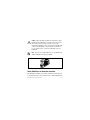
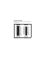
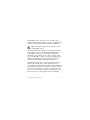
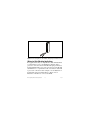
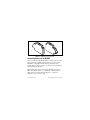
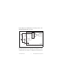
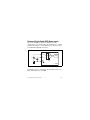
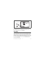
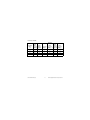
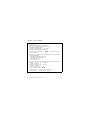
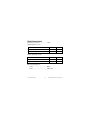
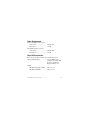
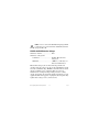
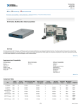
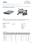
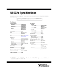
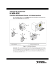
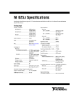
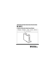
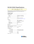
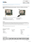
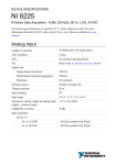
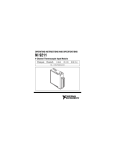
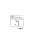
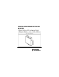
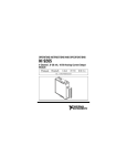
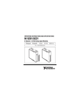
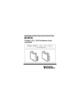
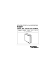
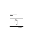
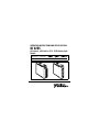
OPERATING INSTRUCTIONS AND SPECIFICATIONS NI 9205 32-Channel, ±200 mV to ±10 V, 16-Bit Analog Input Module Français Deutsch ni.com/manuals This document describes how to use the National Instruments 9205 and includes specifications and pin assignments for the NI 9205. In this document, the NI 9205 with spring terminal and the NI 9205 with DSUB are referred to inclusively as the NI 9205. Visit ni.com/info and enter rdsoftwareversion to determine which software you need for the modules you are using. For information about installing, configuring, and programming the system, refer to the system documentation. Visit ni.com/info and enter cseriesdoc for information about C Series documentation. Note The safety guidelines and specifications in this document are specific to the NI 9205. The other components in the system might not meet the same safety ratings and specifications. Refer to the documentation for each component in the system to determine the safety ratings and specifications for the entire system. Visit ni.com/info and enter cseriesdoc for information about C Series documentation. Safety Guidelines Operate the NI 9205 only as described in these operating instructions. NI 9205 Operating Instructions and Specifications 2 ni.com This icon denotes that the component may be hot. Touching this component may result in bodily injury. Hot Surface Safety Guidelines for Hazardous Voltages You can connect hazardous voltages only to the NI 9205 with spring terminal. Do not connect hazardous voltages to the NI 9205 with DSUB. If hazardous voltages are connected to the module, take the following precautions. A hazardous voltage is a voltage greater than 42.4 Vpk or 60 VDC to earth ground. Ensure that hazardous voltage wiring is performed only by qualified personnel adhering to local electrical standards. Caution Caution Do not mix hazardous voltage circuits and human-accessible circuits on the same module. Make sure that devices and circuits connected to the module are properly insulated from human contact. Caution © National Instruments Corp. 3 NI 9205 Operating Instructions and Specifications When module terminals are hazardous voltage LIVE (>42.4Vpk/60 VDC), you must ensure that devices and circuits connected to the module are properly insulated from human contact. You must use the NI 9940 connector backshell kit to ensure that the terminals are not accessible. Figure 1 shows the NI 9940 connector backshell. Caution Note You can use the NI 9940 connector backshell only with the NI 9205 with spring terminal. Figure 1. NI 9940 Connector Backshell Safety Guidelines for Hazardous Locations The NI 9205 is suitable for use in Class I, Division 2, Groups A, B, C, D, T4 hazardous locations; Class I, Zone 2, AEx nC IIC T4 and NI 9205 Operating Instructions and Specifications 4 ni.com Ex nC IIC T4 hazardous locations; and nonhazardous locations only. Follow these guidelines if you are installing the NI 9205 in a potentially explosive environment. Not following these guidelines may result in serious injury or death. Caution Do not disconnect I/O-side wires or connectors unless power has been switched off or the area is known to be nonhazardous. Do not remove modules unless power has been switched off or the area is known to be nonhazardous. Caution Substitution of components may impair suitability for Class I, Division 2. Caution For Zone 2 applications, install the system in an enclosure rated to at least IP 54 as defined by IEC 60529 and EN 60529. Caution Caution For Zone 2 applications, connected signals must be within the following limits: Capacitance .......................... 0.2 μF max © National Instruments Corp. 5 NI 9205 Operating Instructions and Specifications Special Conditions for Hazardous Locations Use in Europe This equipment has been evaluated as EEx nC IIC T4 equipment under DEMKO Certificate No. 03 ATEX 0324020X. Each module is marked II 3G and is suitable for use in Zone 2 hazardous locations. If you are using the NI 9205 in Gas Group IIC hazardous locations or in ambient temperatures of –40 °C ≤ Ta ≤ 70 °C, you must use the device in an NI chassis that has been evaluated as EEx nC IIC T4, Ex nA IIC T4, or Ex nL IIC T4 equipment. Special Conditions for Marine Applications Some modules are Lloyd’s Register (LR) Type Approved for marine applications. To verify Lloyd’s Register certification, visit ni.com/certification and search for the LR certificate, or look for the Lloyd’s Register mark on the module. To meet radio frequency emission requirements for marine applications, use shielded cables and install the system in a metal enclosure. Suppression ferrites must be installed on power supply inputs near power entries to modules and controllers. Power supply and module cables must be separated on opposite sides of the enclosure and must enter and exit through opposing enclosure walls. Caution NI 9205 Operating Instructions and Specifications 6 ni.com Connecting the NI 9205 The NI 9205 is a 32-channel single-ended/16-channel differential analog input module. AI0 AI1 AI2 AI3 AI4 AI5 AI6 AI7 AI16 AI17 AI18 AI19 AI20 AI21 AI22 AI23 COM DO0 1 2 3 4 5 6 7 8 9 10 11 12 13 14 15 16 17 18 19 20 21 22 23 24 25 26 27 28 29 30 31 32 33 34 35 36 AI8 AI9 AI10 AI11 AI12 AI13 AI14 AI15 AI24 AI25 AI26 AI27 AI28 AI29 AI30 AI31 AISENSE PFI0 AI8 AI9 AI10 AI11 AI12 AI13 AI14 AI15 PFIO COM AI24 AI25 AI26 AI27 AI28 AI29 AI30 AI31 20 21 22 23 24 25 26 27 28 29 30 31 32 33 34 35 36 37 1 2 3 4 5 6 7 8 9 10 11 12 13 14 15 16 17 18 19 AI0 AI1 AI2 AI3 AI4 AI5 AI6 AI7 DO0 COM AI16 AI17 AI18 AI19 AI20 AI21 AI22 AI23 AISENSE Figure 2. NI 9205 Terminal and Pin Assignments © National Instruments Corp. 7 NI 9205 Operating Instructions and Specifications The NI 9205 provides connections for the 32 single-ended or 16 differential analog input channels, as well as one digital input channel, one digital output channel, COM, and AI SENSE. The digital output channel is supported only in CompactRIO systems. Note The NI 9205 with spring terminal has a 36-terminal detachable spring-terminal connector, and the NI 9205 with DSUB has a 37-pin DSUB connector. Each analog input channel has an AI terminal or pin to which you can connect an analog output device. The NI 9205 is capable of an aggregate sampling rate of 250 kS/s. The NI 9205 also supports triggering. Refer to the software help for information about input trigger modes. The NI 9205 channels share a common ground that is isolated from the other modules in the system. All channels share a programmable gain instrumentation amplifier and are multiplexed to an ADC. Each channel also has ±30 V overvoltage protection. For more information about overvoltage protection, refer to the Specifications section. Refer to Figure 3 for an illustration of the input circuitry for one analog input channel on the NI 9205. NI 9205 Operating Instructions and Specifications 8 ni.com Trigger AI+ AI– MUX PGIA Trig ADC 16-bit Filtered Isolated Differential ADC Amplifier NI 9205 AISENSE COM Figure 3. Input Circuitry for One Analog Channel on the NI 9205 Connecting Wires to the NI 9205 Spring-Terminal Connector Use a flathead screwdriver with a blade smaller than 2.3 × 1.0 mm (0.09 × 0.04 in.) to connect wires to the detachable spring-terminal connector. Insert the screwdriver into a spring clamp activation slot and press a wire into the corresponding connector terminal, then remove the screwdriver to clamp the wire into the terminal. Refer to the Specifications section for more information about spring-terminal wiring. Refer to Figure 4 for an illustration of connecting wires to the NI 9205 with spring terminal. © National Instruments Corp. 9 NI 9205 Operating Instructions and Specifications Figure 4. Connecting Wires to the NI 9205 with Spring-Terminal Connector Wiring for High-Vibration Applications If an application is subject to high vibration, National Instruments recommends that you use a backshell kit or shielded cable to protect the connections. For the NI 9205 with spring terminal, use the NI 9940 backshell to protect the connections. For the NI 9205 with DSUB, use a 37-pin shielded cable or the NI 9933 backshell to protect the connections. Refer to Figure 1 for an illustration of the NI 9940 connector backshell. Refer to Figure 5 for an illustration of the NI 9933 connector backshell. NI 9205 Operating Instructions and Specifications 10 ni.com Figure 5. NI 9933 Connector Backshell Connecting Devices to the NI 9205 You can connect the NI 9205 directly to a variety of devices and other signal sources. Make sure the devices you connect to the NI 9205 are compatible with the input specifications of the module. Refer to the Specifications section for more information about the input specifications. When connecting various sources to the NI 9205, you can use differential, single-ended, or a combination of differential and single-ended connections. Refer to Figures 6, 7, and 8 for diagrams of each connection type. © National Instruments Corp. 11 NI 9205 Operating Instructions and Specifications Differential Measurements You can use a differential measurement configuration to attain more accurate measurements and less noise. A differential measurement configuration requires two inputs for each measurement, thus reducing the number of available channels on the NI 9205 to 16. Table 1 shows the signal pairs that are valid for differential connection configurations with the NI 9205. Table 1. Differential Pairs Channel 0 1 2 3 4 5 6 7 Signal+ AI0 AI1 AI2 AI3 AI4 AI5 AI6 AI7 Signal– AI8 AI9 AI10 AI11 AI12 AI13 AI14 AI15 NI 9205 Operating Instructions and Specifications Channel 16 17 18 19 20 21 22 23 12 Signal+ AI16 AI17 AI18 AI19 AI20 AI21 AI22 AI23 Signal– AI24 AI25 AI26 AI27 AI28 AI29 AI30 AI31 ni.com Refer to Figure 6 for an illustration of connecting a device to the NI 9205 using differential connections. AI0+ AI0– (AI8)1 V1 MUX PGIA ADC AI1+ Vcm V2 AI1– (AI9)1 COM NI 9205 1 This signal name indicates the differential pair. Refer to Table1 for a list of differential signal pairs. Figure 6. Connecting a Device to the NI 9205 Using Differential Connections In a differential connection configuration, the NI 9205 rejects the common-mode noise voltage, Vcm, during the measurement of V1. © National Instruments Corp. 13 NI 9205 Operating Instructions and Specifications Referenced Single-Ended (RSE) Measurements You can use an RSE measurement configuration to take measurements on 32 channels when all channels share a common ground. Refer to Figure 7 for an illustration of connecting a device to the NI 9205 using RSE connections. AI1 MUX AI2 PGIA ADC V1 V2 COM NI 9205 Figure 7. Connecting a Device to the NI 9205 Using RSE Connections In an RSE connection configuration, the NI 9205 measures each input channel with respect to COM. NI 9205 Operating Instructions and Specifications 14 ni.com Note If you leave COM unconnected, the signals float outside the working input range of the NI 9205. This may result in unreliable measurements because there is no way to ensure that the input signal is within 10 V of COM. Non-Referenced, Single-Ended (NRSE) Measurements You can use an NRSE measurement configuration to take measurements on all 32 channels while reducing noise more effectively than with an RSE connection configuration. This configuration provides remote sense for the negative (–) input of the PGIA that is shared by all channels configured for NRSE mode. The behavior of this configuration is similar to the behavior of RSE connections, but it provides improved noise rejection. Refer to Figure 8 for an illustration of connecting a device to the NI 9205 using NRSE connections. © National Instruments Corp. 15 NI 9205 Operating Instructions and Specifications AI1 MUX AI2 PGIA ADC V1 V2 COM AISENSE NI 9205 Figure 8. Connecting a Device to the NI 9205 Using NRSE Connections In an NRSE connection configuration, the NI 9205 measures each input channel with respect to AI SENSE. Sleep Mode This module supports a low-power sleep mode. Support for sleep mode at the system level depends on the chassis that the module is plugged into. Refer to the chassis manual for information about support for sleep mode. If the chassis supports sleep mode, refer to the software help for information about enabling sleep mode. Visit ni.com/info and enter cseriesdoc for information about C Series documentation. NI 9205 Operating Instructions and Specifications 16 ni.com Typically, when a system is in sleep mode, you cannot communicate with the modules. In sleep mode, the system consumes minimal power and may dissipate less heat than it does in normal mode. Refer to the Specifications section for more information about power consumption and thermal dissipation. Specifications The following specifications are typical for the range –40 to 70 °C unless otherwise noted. All voltages are relative to COM unless otherwise noted. Analog Input Characteristics Number of channels.......................... 32 single-ended or 16 differential analog input channels, 1 digital input channel, and 1 digital output channel ADC resolution................................. 16 bits DNL .................................................. No missing codes guaranteed © National Instruments Corp. 17 NI 9205 Operating Instructions and Specifications INL.................................................... Refer to the AI Absolute Accuracy Tables and Formulas MTBF ............................................... 775,832 hours at 25 °C; Bellcore Issue 6, Method 1, Case 3, Limited Part Stress Method Note Contact NI for Bellcore MTBF specifications at other temperatures or for MIL-HDBK-217F specifications. Conversion time R Series Expansion chassis ........ 4.50 μs (222 kS/s) All other chassis ......................... 4.00 μs (250 kS/s) Input coupling................................... DC Nominal input ranges........................ ±10 V, ±5 V, ±1 V, ±0.2 V Minimum overrange (for 10 V range) ................................ 4% Maximum working voltage for analog inputs (signal + common mode) .................. Each channel must remain within ±10.4 V of common NI 9205 Operating Instructions and Specifications 18 ni.com Input impedance (AI-to-COM) Powered on ................................. >10 GΩ in parallel with 100 pF Powered off/overload ................. 4.7 kΩ min Input bias current .............................. ±100 pA Crosstalk (at 100 kHz) Adjacent channels ...................... –65 dB Non-adjacent channels ............... –70 dB Analog bandwidth............................. 370 kHz Overvoltage protection AI channel (0 to 31) ................... ±30 V (one channel only) AISENSE ................................... ±30 V CMRR (DC to 60 Hz)....................... 100 dB © National Instruments Corp. 19 NI 9205 Operating Instructions and Specifications Typical AI+ to AI– CMRR graph AI <0...31> CMRR 140 CMRR (dB) 120 100 80 60 40 60 100 1k Frequency (Hz) 10 k 100 k Settling time for multichannel measurements, accuracy, all ranges ±120 ppm of full-scale step (±8 LSB)..................................... 4 μs convert interval ±30 ppm of full-scale step (±2 LSB)..................................... 8 μs convert interval NI 9205 Operating Instructions and Specifications 20 ni.com Analog triggers Number of triggers ..................... 1 Resolution................................... 10 bits, 1 in 1,024 Bandwidth (–3 dB) ..................... 370 kHz Accuracy..................................... ±1% of full scale Scaling coefficients Nominal Range (V) Typical Scaling Coefficient (μV/LSB) ±10 328 ±5 164.2 ±1 32.8 ±0.2 6.57 © National Instruments Corp. 21 NI 9205 Operating Instructions and Specifications AI Absolute Accuracy Tables and Formulas The values in the following tables are based on calibrated scaling coefficients, which are stored in the onboard EEPROM. Accuracy summary Nominal Range (V) Absolute Accuracy Random Noise, at Full Scale* (μV) σ (μVrms) Sensitivity† (μV) ±10 6,230 240 96.0 ±5 3,230 116 46.4 ±1 690 26 10.4 ±0.2 174 10 4.0 * Absolute accuracy values at full scale on the analog input channels assume the device is operating within 70 °C of the last external calibration and are valid for averaging 100 samples immediately following internal calibration. Refer to the Absolute accuracy formulas for more information. † Sensitivity is the smallest voltage change that can be detected. It is a function of noise. NI 9205 Operating Instructions and Specifications 22 ni.com Accuracy details Nominal Range (V) Residual Gain Error Gain (ppm of Tempco Reading) (ppm/°C) Reference Tempco Residual Offset Error (ppm of Range) Offset Tempco (ppm of Range/°C) INL Error (ppm of Range) ±10 115 11 5 20 44 76 ±5 135 11 5 20 47 76 ±1 155 11 5 25 66 76 ±0.2 215 11 5 40 162 76 © National Instruments Corp. 23 NI 9205 Operating Instructions and Specifications Absolute accuracy formulas AbsoluteAccuracy = Reading · GainError + Range · OffsetError + NoiseUncertainty GainError = ResidualGainError + GainTempco · TempChangeFromLastInternalCal + ReferenceTempco · TempChangeFromLastExternalCal OffsetError = ResidualOffsetError + OffsetTempco · TempChangeFromLastInternalCal + INL_Error NoiseUncertainty = (RandomNoise · 3) / 100 for a coverage factor of 3 σ and averaging 100 points. Absolute accuracy at full scale on the analog input channels is determined using the following assumptions: TempChangeFromLastExternalCal = 70 °C TempChangeFromLastInternalCal = 1 °C NumberOfReadings = 100 CoverageFactor = 3 σ For example, on the 10 V range, the absolute accuracy at full scale is as follows: GainError = 115 ppm + 11 ppm · 1 + 5 ppm · 70 GainError = 476 ppm OffsetError = 20 ppm + 44 ppm · 1 + 76 ppm OffsetError = 140 ppm NoiseUncertainty = (240 μV · 3) / 100 Noise Uncertainty = 72 μV AbsoluteAccuracy = 10 V · 476 ppm + 10 V · 140 ppm + 72 μV AbsoluteAccuracy = 6,232 μV (rounds to 6,230 μV) NI 9205 Operating Instructions and Specifications 24 ni.com Digital Characteristics Overvoltage protection ..................... ±30 V Digital input logic levels Level Min Max Input high voltage (VIH) 2.0 V 3.3 V Input low voltage (VIL) 0V 0.34 V Min Max Output high voltage (VOH), sourcing 75 μA 2.1 V 3.3 V Output low voltage (VOL), sinking 250 μA 0V 0.4 V Digital output logic levels Level External digital triggers Source......................................... PFI0 Delay .......................................... 100 ns max © National Instruments Corp. 25 NI 9205 Operating Instructions and Specifications Power Requirements Power consumption from chassis Active mode ............................... 625 mW max Sleep mode ................................. 15 mW Thermal dissipation (at 70 °C) Active mode ............................... 625 mW max Sleep mode ................................. 15 mW Physical Characteristics If you need to clean the module, wipe it with a dry towel. Spring-terminal wiring...................... 18 to 28 AWG copper conductor wire with 7 mm (0.28 in.) of insulation stripped from the end Weight NI 9205 with spring terminal ..... 158 g (5.8 oz) NI 9205 with DSUB................... 148 g (5.3 oz) NI 9205 Operating Instructions and Specifications 26 ni.com Safety Maximum Voltage1 Connect only voltages that are within the following limits. AI, PFI0, and DO-to-COM............... ±30 VDC NI 9205 with Spring Terminal Isolation Voltages Channel-to-channel........................... None Channel-to-earth ground Continuous ................................. 250 Vrms, Measurement Category II Withstand.................................... 2,300 Vrms, verified by a 5 s dielectric withstand test Measurement Category II is for measurements performed on circuits directly connected to the electrical distribution system. This category refers to local-level electrical distribution, such as that provided by a standard wall outlet, for example, 115 V for U.S. or 230 V for Europe. 1 The maximum voltage that can be applied or output between AI and COM without creating a safety hazard. © National Instruments Corp. 27 NI 9205 Operating Instructions and Specifications Caution Do not connect the NI 9205 with spring terminal to signals or use for measurements within Measurement Categories III or IV. NI 9205 with DSUB Isolation Voltages Channel-to-channel........................... None Channel-to-earth ground Continuous ................................. 60 VDC, Measurement Category I Withstand.................................... 1,000 Vrms, verified by a 5 s dielectric withstand test Measurement Category I is for measurements performed on circuits not directly connected to the electrical distribution system referred to as MAINS voltage. MAINS is a hazardous live electrical supply system that powers equipment. This category is for measurements of voltages from specially protected secondary circuits. Such voltage measurements include signal levels, special equipment, limited-energy parts of equipment, circuits powered by regulated low-voltage sources, and electronics. NI 9205 Operating Instructions and Specifications 28 ni.com Caution Do not connect the NI 9205 with DSUB to signals or use for measurements within Measurement Categories II, III, or IV. Safety Standards This product is designed to meet the requirements of the following standards of safety for electrical equipment for measurement, control, and laboratory use: • IEC 61010-1, EN 61010-1 • UL 61010-1, CSA 61010-1 Note For UL and other safety certifications, refer to the product label or visit ni.com/certification, search by module number or product line, and click the appropriate link in the Certification column. Hazardous Locations U.S. (UL) .......................................... Class I, Division 2, Groups A, B, C, D, T4; Class I, Zone 2, AEx nC IIC T4 © National Instruments Corp. 29 NI 9205 Operating Instructions and Specifications Canada (C-UL) ................................. Class I, Division 2, Groups A, B, C, D, T4; Class I, Zone 2, Ex nC IIC T4 Europe (DEMKO)............................. EEx nC IIC T4 Environmental National Instruments C Series modules are intended for indoor use only but may be used outdoors if installed in a suitable enclosure. Refer to the manual for the chassis you are using for more information about meeting these specifications. Operating temperature (IEC 60068-2-1, IEC 60068-2-2) ..... –40 to 70 °C Storage temperature (IEC 60068-2-1, IEC 60068-2-2) ..... –40 to 85 °C Ingress protection.............................. IP 40 Operating humidity (IEC 60068-2-56).............................. 10 to 90% RH, noncondensing NI 9205 Operating Instructions and Specifications 30 ni.com Storage humidity (IEC 60068-2-56).............................. 5 to 95% RH, noncondensing Maximum altitude............................. 2,000 m Pollution Degree (IEC 60664) .......... 2 Shock and Vibration To meet these specifications, you must panel mount the system and use a backshell kit or shielded cable to protect the connections. Use the NI 9940 backshell for the NI 9205 with spring terminal and a 37-pin shielded cable or the NI 9933 backshell for the NI 9205 with DSUB. Operating vibration Random (IEC 60068-2-64)......... 5 grms, 10 to 500 Hz Sinusoidal (IEC 60068-2-6) ....... 5 g, 10 to 500 Hz Operating shock (IEC 60068-2-27).............................. 30 g, 11 ms half sine, 50 g, 3 ms half sine, 18 shocks at 6 orientations © National Instruments Corp. 31 NI 9205 Operating Instructions and Specifications Electromagnetic Compatibility This product is designed to meet the requirements of the following standards of EMC for electrical equipment for measurement, control, and laboratory use: • EN 61326 EMC requirements; Industrial Immunity • EN 55011 Emissions; Group 1, Class A • CE, C-Tick, ICES, and FCC Part 15 Emissions; Class A Note For EMC compliance, operate this device with shielded cabling. CE Compliance This product meets the essential requirements of applicable European directives, as amended for CE markings, as follows: • 2006/95/EC; Low-Voltage Directive (safety) • 2004/108/EC; Electromagnetic Compatibility Directive (EMC) Note Refer to the Declaration of Conformity (DoC) for this product for any additional regulatory compliance information. To obtain the DoC for this product, visit NI 9205 Operating Instructions and Specifications 32 ni.com ni.com/certification, search by module number or product line, and click the appropriate link in the Certification column. Environmental Management National Instruments is committed to designing and manufacturing products in an environmentally responsible manner. NI recognizes that eliminating certain hazardous substances from our products is beneficial not only to the environment but also to NI customers. For additional environmental information, refer to the NI and the Environment Web page at ni.com/environment. This page contains the environmental regulations and directives with which NI complies, as well as other environmental information not included in this document. Waste Electrical and Electronic Equipment (WEEE) EU Customers At the end of their life cycle, all products must be sent to a WEEE recycling center. For more information about WEEE recycling centers and National Instruments WEEE initiatives, visit ni.com/ environment/weee.htm. © National Instruments Corp. 33 NI 9205 Operating Instructions and Specifications ⬉ᄤֵᙃѻક∵ᶧࠊㅵ⧚ࡲ⊩ ˄Ё RoHS˅ Ёᅶ᠋ National Instruments ヺড়Ё⬉ᄤֵᙃ ѻકЁ䰤ࠊՓ⫼ᶤѯ᳝ᆇ⠽䋼ᣛҸ (RoHS)DŽ݇Ѣ National Instruments Ё RoHS ড়㾘ᗻֵᙃˈ䇋ⱏᔩ ni.com/environment/rohs_chinaDŽ (For information about China RoHS compliance, go to ni.com/ environment/rohs_china.) Calibration (Analog Input) You can obtain the calibration certificate and information about calibration services for the NI 9205 at ni.com/calibration. Calibration interval ........................... 2 years Where to Go for Support The National Instruments Web site is your complete resource for technical support. At ni.com/support you have access to everything from troubleshooting and application development self-help resources to email and phone assistance from NI Application Engineers. National Instruments corporate headquarters is located at 11500 North Mopac Expressway, Austin, Texas, 78759-3504. NI 9205 Operating Instructions and Specifications 34 ni.com National Instruments also has offices located around the world to help address your support needs. For telephone support in the United States, create your service request at ni.com/support and follow the calling instructions or dial 512 795 8248. For telephone support outside the United States, contact your local branch office: Australia 1800 300 800, Austria 43 662 457990-0, Belgium 32 (0) 2 757 0020, Brazil 55 11 3262 3599, Canada 800 433 3488, China 86 21 5050 9800, Czech Republic 420 224 235 774, Denmark 45 45 76 26 00, Finland 358 (0) 9 725 72511, France 01 57 66 24 24, Germany 49 89 7413130, India 91 80 41190000, Israel 972 3 6393737, Italy 39 02 41309277, Japan 0120-527196, Korea 82 02 3451 3400, Lebanon 961 (0) 1 33 28 28, Malaysia 1800 887710, Mexico 01 800 010 0793, Netherlands 31 (0) 348 433 466, New Zealand 0800 553 322, Norway 47 (0) 66 90 76 60, Poland 48 22 3390150, Portugal 351 210 311 210, Russia 7 495 783 6851, Singapore 1800 226 5886, Slovenia 386 3 425 42 00, South Africa 27 0 11 805 8197, Spain 34 91 640 0085, Sweden 46 (0) 8 587 895 00, Switzerland 41 56 2005151, Taiwan 886 02 2377 2222, Thailand 662 278 6777, Turkey 90 212 279 3031, United Kingdom 44 (0) 1635 523545 © National Instruments Corp. 35 NI 9205 Operating Instructions and Specifications National Instruments, NI, ni.com, and LabVIEW are trademarks of National Instruments Corporation. Refer to the Terms of Use section on ni.com/legal for more information about National Instruments trademarks. Other product and company names mentioned herein are trademarks or trade names of their respective companies. For patents covering National Instruments products, refer to the appropriate location: Help»Patents in your software, the patents.txt file on your CD, or ni.com/patents. © 2006–2008 National Instruments Corp. All rights reserved. 374188D-01 Feb08