1
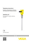
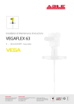
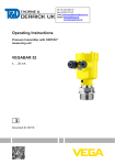
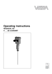
Operating Instructions
Capacitive rod electrode for continuous
level measurement of adhesive products
VEGACAL 64
4 … 20 mA/HART - two-wire
Document ID: 30030
Contents
Contents
About this document
1.1 Function ........................................................................................................................... 4
1.2 Target group ..................................................................................................................... 4
1.3 Symbolism used ............................................................................................................... 4
2
For your safety
2.1 Authorised personnel ....................................................................................................... 5
2.2 Appropriate use ................................................................................................................ 5
2.3 Warning about incorrect use............................................................................................. 5
2.4 General safety instructions ............................................................................................... 5
2.5 Safety label on the instrument .......................................................................................... 6
2.6 CE conformity................................................................................................................... 6
2.7 FulfillmentofNAMURrecommendations ......................................................................... 6
2.8 Safety instructions for Ex areas ........................................................................................ 6
2.9 Environmental instructions ............................................................................................... 6
3
Product description
3.1 Configuration .................................................................................................................... 7
3.2 Principle of operation........................................................................................................ 8
3.3 Operation ......................................................................................................................... 9
3.4 Packaging, transport and storage ................................................................................... 10
3.5 Accessories and replacement parts ............................................................................... 10
4
Mounting
4.1 General instructions ....................................................................................................... 12
4.2 Mountinginstructions ..................................................................................................... 13
5
Connecting to power supply
5.1 Preparing the connection ............................................................................................... 15
5.2 Connection procedure .................................................................................................... 16
5.3 Wiring plan, single chamber housing.............................................................................. 17
5.4 Wiring plan, double chamber housing ............................................................................ 19
5.5 Wiring plan, double chamber housing Ex d .................................................................... 21
5.6 Wiring plan - version IP 66/IP 68, 1 bar........................................................................... 22
6
Set up with the display and adjustment module PLICSCOM
6.1 Short description ............................................................................................................ 23
6.2 Insert display and adjustment module ............................................................................ 23
6.3 Adjustment system ......................................................................................................... 24
6.4 Setup steps .................................................................................................................... 25
6.5 Menuschematic ............................................................................................................. 29
6.10 Saving the parameter adjustment data ........................................................................... 31
7
Set up with PACTware and other adjustment programs
7.1 Connect the PC .............................................................................................................. 32
7.2 Parameter adjustment with PACTware ............................................................................ 33
7.3 ParameteradjustmentwithAMS™andPDM ................................................................. 34
7.4 Saving the parameter adjustment data ........................................................................... 34
8 Maintenanceandfaultrectification
8.1 Maintenance .................................................................................................................. 35
8.2 Rectify faults ................................................................................................................... 35
2
VEGACAL 64 • 4 … 20 mA/HART - two-wire
30030-EN-130917
1
Contents
8.3
8.4
9
Exchanging the electronics module ................................................................................ 37
How to proceed in case of repair .................................................................................... 37
Dismounting
9.1 Dismounting steps.......................................................................................................... 39
9.2 Disposal ......................................................................................................................... 39
10 Supplement
10.1 Technical data ................................................................................................................ 40
10.2 Dimensions .................................................................................................................... 45
Supplementary documentation
Information:
Supplementary documents appropriate to the ordered version come
withthedelivery.Youcanfindthemlistedinchapter"Product description".
30030-EN-130917
Instructions manuals for accessories and replacement parts
Tip:
ToensurereliablesetupandoperationofyourVEGACAL64,weoffer
accessories and replacement parts. The corresponding documentations are:
•
•
•
•
27720 - VEGADIS 61
30531 - Electronics module VEGACAL series 60
34296 - Protective cover
31088-FlangesaccordingtoDIN-EN-ASME-JIS
Editing status: 2013-08-21
VEGACAL 64 • 4 … 20 mA/HART - two-wire
3
1 About this document
1
About this document
1.1
Function
1.2
Target group
1.3
Symbolism used
This operating instructions manual provides all the information you
need for mounting, connection and setup as well as important instructionsformaintenanceandfaultrectification.Pleasereadthisinformation before putting the instrument into operation and keep this manual
accessible in the immediate vicinity of the device.
This operating instructions manual is directed to trained specialist
personnel. The contents of this manual should be made available to
these personnel and put into practice by them.
Information, tip, note
This symbol indicates helpful additional information.
Caution: If this warning is ignored, faults or malfunctions can result.
Warning: If this warning is ignored, injury to persons and/or serious
damage to the instrument can result.
Danger: If this warning is ignored, serious injury to persons and/or
destruction of the instrument can result.
•
→
1
Ex applications
This symbol indicates special instructions for Ex applications.
List
The dot set in front indicates a list with no implied sequence.
Action
This arrow indicates a single action.
Sequence of actions
Numbers set in front indicate successive steps in a procedure.
Battery disposal
This symbol indicates special information about the disposal of batteries and accumulators.
30030-EN-130917
4
VEGACAL 64 • 4 … 20 mA/HART - two-wire
2 For your safety
2
2.1
For your safety
Authorised personnel
All operations described in this operating instructions manual must
be carried out only by trained specialist personnel authorised by the
plant operator.
During work on and with the device the required personal protective
equipment must always be worn.
2.2
Appropriate use
VEGACAL 64 is a sensor for continuous level measurement.
Youcanfinddetailedinformationontheapplicationrangeinchapter
"Product description".
Operational reliability is ensured only if the instrument is properly
usedaccordingtothespecificationsintheoperatinginstructions
manual as well as possible supplementary instructions.
For safety and warranty reasons, any invasive work on the device
beyond that described in the operating instructions manual may be
carried out only by personnel authorised by the manufacturer. Arbitraryconversionsormodificationsareexplicitlyforbidden.
2.3
Warning about incorrect use
2.4
General safety instructions
Inappropriate or incorrect use of the instrument can give rise to
application-specifichazards,e.g.vesseloverfillordamagetosystem
components through incorrect mounting or adjustment.
This is a state-of-the-art instrument complying with all prevailing
regulations and guidelines. The instrument must only be operated in a
technicallyflawlessandreliablecondition.Theoperatorisresponsible
for the trouble-free operation of the instrument.
During the entire duration of use, the user is obliged to determine the
compliance of the necessary occupational safety measures with the
current valid rules and regulations and also take note of new regulations.
The safety instructions in this operating instructions manual, the national installation standards as well as the valid safety regulations and
accident prevention rules must be observed by the user.
30030-EN-130917
For safety and warranty reasons, any invasive work on the device
beyond that described in the operating instructions manual may be
carried out only by personnel authorised by the manufacturer. Arbitraryconversionsormodificationsareexplicitlyforbidden.
The safety approval markings and safety tips on the device must also
be observed.
VEGACAL 64 • 4 … 20 mA/HART - two-wire
5
2 For your safety
2.5
Safety label on the instrument
2.6
CE conformity
The safety approval markings and safety tips on the device must be
observed.
ThisdevicefulfillsthelegalrequirementsoftheapplicableECguidelines.ByattachingtheCEmark,VEGAprovidesaconfirmationof
successfultesting.YoucanfindtheCEconformitydeclarationinthe
downloadareaof"www.vega.com".
2.7 FulfillmentofNAMURrecommendations
NAMURistheautomationtechnologyuserassociationintheprocess
industryinGermany.ThepublishedNAMURrecommendationsare
acceptedasthestandardinfieldinstrumentation.
ThedevicefulfillstherequirementsofthefollowingNAMURrecommendations:
•
•
•
NE 21 – Electromagnetic compatibility of equipment
NE 43 – Signal level for malfunction information from measuring
transducers
NE53–Compatibilityoffielddevicesanddisplay/adjustment
components
For further information see www.namur.de.
2.8
Safety instructions for Ex areas
2.9
Environmental instructions
PleasenotetheEx-specificsafetyinformationforinstallationandoperation in Ex areas. These safety instructions are part of the operating
instructions manual and come with the Ex-approved instruments.
Protection of the environment is one of our most important duties.
That is why we have introduced an environment management system
with the goal of continuously improving company environmental protection.Theenvironmentmanagementsystemiscertifiedaccording
to DIN EN ISO 14001.
Pleasehelpusfulfillthisobligationbyobservingtheenvironmental
instructions in this manual:
•
•
Chapter"Packaging, transport and storage"
Chapter"Disposal"
30030-EN-130917
6
VEGACAL 64 • 4 … 20 mA/HART - two-wire
3 Product description
3
Product description
3.1 Configuration
Scope of delivery
The scope of delivery encompasses:
Constituent parts
The VEGACAL 64 consists of the components:
•
•
•
•
•
Level sensor VEGACAL 64
Documentation
– this operating instructions manual
– SafetyManual35593"VEGACAL series 60 - 4 … 20 mA/
HART"(optional)
– Operatinginstructionsmanual27835"Display and adjustment
module PLICSCOM"(optional)
– Supplementaryinstructionsmanual31708"Heating for display
and adjustment module"(optional)
– Supplementaryinstructionsmanual"Plug connector for continuously measuring sensors"(optional)
– Ex-specific"Safety instructions"(withExversions)
– ifnecessary,furthercertificates
Processfittingwithprobe
Housing with electronics
Housing cover, optionally available with display and adjustment
module
1
2
3
Fig. 1: VEGACAL 64 - rod version with plastic housing
30030-EN-130917
1 Housing cover with integrated display and adjustment module (optional)
2 Housing with electronics
3 Processfitting
Type plate
Thenameplatecontainsthemostimportantdataforidentificationand
use of the instrument:
VEGACAL 64 • 4 … 20 mA/HART - two-wire
7
3 Product description
1
15
2
14
3
13
4
12
5
6
7
8
11
10
9
Fig. 2: Layout of the type label (example)
1 Instrument type
2 Product code
3 Approvals
4 Process and ambient temperature, process pressure
5 Power supply and signal output, electronics
6 Protection rating
7 Probe length
8 Order number
9 Serial number of the instrument
10 Material, wetted parts
11 Symbol of the device protection class
12 Reminder to observe the instrument documentation
13 ID numbers, instrument documentation
14 NotifiedauthorityforCEmarking
15 Approval directives
With the serial number, you can access the delivery data of the instrument via www.vega.com,"VEGA Tools"and"serial number search".
Inadditiontothetypelabeloutside,youcanalsofindtheserialnumber on the inside of the instrument.
Area of application
3.2
Principle of operation
VEGACAL 64 is a level sensor with fully insulated probe for continuous level measurement.
The electronics functions according to the admittance principle
(phase-selectiveadmittanceprocessing).
It is designed for industrial use in all areas of process technology and
can be applied in all areas of industrial process measurement.
Fully insulated probes such as VEGACAL 64 are preferably used in
conductive liquids.
Fully insulated probes like VEGACAL 64 are preferably used in conductive, very adhesive liquids.
The instrument can also be used problem-free in corrosive products.
Functional principle
8
Probe, measured product and vessel wall form an electrical capacitor.
Thecapacitanceisinfluencedbythreemainfactors.
VEGACAL 64 • 4 … 20 mA/HART - two-wire
30030-EN-130917
The capacitive measuring principle places no special requirements
oninstallation.Hence,manydifferentapplicationscanbeequipped
with VEGACAL 64.
3 Product description
1
2
3
Fig. 3: Functional principle - Plate capacitor
1
2
3
Distance between the electrode surfaces
Size of the electrode surfaces
Type of dielectric between the electrodes
The probe and the vessel wall are the capacitor plates. The measured
product and the insulation are the dielectric. Due to the higher dielectric constant of the insulation and the conductive product compared to
air, the capacitance increases as the probe is gradually covered.
The capacitance as well as the resistance change are converted by
the electronics module into a level-proportional signal.
Voltage supply
4 … 20 mA/HART two-wire electronics for voltage supply and measured value transmission on the same cable.
Thesupplyvoltagerangecandifferdependingontheinstrument
version.
Thedataforpowersupplyarespecifiedinchapter"Technical data".
The optional background lighting of the display and adjustment
module is powered by the sensor. A certain level of operating voltage
isrequiredforthis.Youcanfindtheexactvoltagespecificationsin
chapter"Technical data".
Theoptionalheatingrequiresitsownoperatingvoltage.Youcanfind
detailsinthesupplementaryinstructionsmanual"Heating for display
and adjustment module".
This function is generally not available for approved instruments.
3.3
Operation
The instrument can be adjusted with the following adjustment media:
30030-EN-130917
•
•
•
•
With the display and adjustment module
withthesuitableVEGADTMinconjunctionwithanadjustment
softwareaccordingtotheFDT/DTMstandard,e.g.PACTwareand
PC
withmanufacturer-specificadjustmentprogramsAMS™orPDM
With a HART handheld
VEGACAL 64 • 4 … 20 mA/HART - two-wire
9
3 Product description
Packaging
3.4
Packaging, transport and storage
Your instrument was protected by packaging during transport. Its
capacity to handle normal loads during transport is assured by a test
based on ISO 4180.
The packaging of standard instruments consists of environmentfriendly, recyclable cardboard. For special versions, PE foam or PE
foil is also used. Dispose of the packaging material via specialised
recycling companies.
Transport
Transport must be carried out in due consideration of the notes on the
transport packaging. Nonobservance of these instructions can cause
damage to the device.
Transport inspection
The delivery must be checked for completeness and possible transit
damage immediately at receipt. Ascertained transit damage or concealed defects must be appropriately dealt with.
Storage
Uptothetimeofinstallation,thepackagesmustbeleftclosedand
stored according to the orientation and storage markings on the
outside.
Unlessotherwiseindicated,thepackagesmustbestoredonlyunder
the following conditions:
Storage and transport
temperature
PLICSCOM
•
•
•
•
•
•
•
Not in the open
Dry and dust free
Not exposed to corrosive media
Protected against solar radiation
Avoiding mechanical shock and vibration
Storageandtransporttemperatureseechapter"Supplement Technical data - Ambient conditions"
Relative humidity 20 … 85 %
3.5
Accessories and replacement parts
ThedisplayandadjustmentmodulePLICSCOMisusedformeasured
value indication, adjustment and diagnosis. It can be inserted into the
sensor or the external display and adjustment unit and removed at
any time.
Youcanfindfurtherinformationintheoperatinginstructions"Display
and adjustment module PLICSCOM"(Document-ID27835).
VEGACONNECT
The interface adapter VEGACONNECT enables the connection of
communication-capableinstrumentstotheUSBinterfaceofaPC.For
parameter adjustment of these instruments, the adjustment software
PACTwarewithVEGA-DTMisrequired.
VEGADIS 62
10
VEGADIS 62 is suitable for measured value indication and adjustment
of sensors with HART protocol. It is looped into the 4 … 20 mA/HART
signal cable.
VEGACAL 64 • 4 … 20 mA/HART - two-wire
30030-EN-130917
Youcanfindfurtherinformationintheoperatinginstructions"Interface
adapter VEGACONNECT"(Document-ID32628).
3 Product description
Youcanfindfurtherinformationintheoperatinginstructions"VEGADIS 62"(Document-ID36469).
Protective cap
The protective cover protects the sensor housing against soiling and
intense heat from solar radiation.
Youwillfindadditionalinformationinthesupplementaryinstructions
manual"Protective cover"(Document-ID34296).
Flanges
Screwedflangesareavailableindifferentversionsaccordingtothe
following standards: DIN 2501, EN 1092-1, BS 10, ANSI B 16.5,
JISB2210-1984,GOST12821-80.
Youcanfindadditionalinformationinthesupplementaryinstructions
manual"Flanges according to DIN-EN-ASME-JIS"(Document-ID
31088).
Screening tube adapter
Condensation
In case of strong condensation, the draining of condensed water
can change the measurement accuracy. The suitable version is the
Screening against condensation.Thecondensationcandrainoff
outside on the screening tube adapter.
Typical applications of the screening tube adapters are e.g. for
condensation or sockets. Apart from the standard version, there is
a second version for vacuum with a sepcial seal. When the screening tube adapter is submerged in liquid, we recommend the use of a
vacuum-tight version.
Socket
In case of long sockets, the screening tube can increase the sensitivityoftheprobebycompensatingtheinfluencesofthesocket.The
suitable version is Capacitive screening, vacuum-tight.
30030-EN-130917
When the probe is mounted laterally, buildup can accumulate in the
socket. A screening tube makes the covered part of the probe inactive
andhenceinsensitivetoinfluencefrombuildupandsocket.Hence,
thescreeningtubeadapterexcludeschanginginfluencescausedby
the medium and ensures stable measurement conditions. The suitable version is Capacitive screening, vacuum-tight.
VEGACAL 64 • 4 … 20 mA/HART - two-wire
11
4Mounting
4
4.1
Mounting
General instructions
Suitability for the process Makesurethatallpartsoftheinstrumentcomingindirectcontact
conditions
with the process, especially the sensor element, process seal and
processfitting,aresuitablefortheexistingprocessconditions,such
as process pressure, process temperature as well as the chemical
properties of the medium.
Youcanfindthespecificationsinchapter"Technical data"andonthe
nameplate.
Installation position
Select an installation position you can easily reach for mounting and
connectingaswellaslaterretrofittingofadisplayandadjustment
module. The housing can be rotated by 330° without the use of any
tools. You can also install the display and adjustment module in four
differentpositions(eachdisplacedby90°).
Welding work
Before beginning the welding work, remove the electronics module
from the sensor. By doing this, you avoid damage to the electronics
through inductive coupling.
Handling
With threaded versions, the housing must not be used to screw in the
instrument. Applying tightening forces on the housing can damage its
internal parts.
Usethehexagonforscrewingin.
Moisture
Usetherecommendedcables(seechapter"Connecting to power
supply")andtightenthecablegland.
You can give your instrument additional protection against moisture
penetration by leading the connection cable downward in front of the
cableentry.Rainandcondensationwatercanthusdrainoff.Thisapplies mainly to outdoor mounting as well as installation in areas where
highhumidityisexpected(e.g.throughcleaningprocesses)oron
cooled or heated vessels.
Pressure/Vacuum
12
Theprocessfittingmustbesealedifthereisgaugeorlowpressurein
the vessel. Before use, check if the seal material is resistant against
the measured product and the process temperature.
VEGACAL 64 • 4 … 20 mA/HART - two-wire
30030-EN-130917
Fig. 4: Measures against moisture penetration
4Mounting
Themax.permissiblepressureisspecifiedinchapter"Technical
data"oronthetypelabelofthesensor.
Insulatingmeasures,suchase.g.coveringthethreadwithteflontape,
can interrupt the necessary electrical connection with metal vessels.
For this reason, ground the probe on the vessel or use a conductive
seal material.
Vessel material
Metal vessel
Makesurethatthemechanicalconnectionoftheprobetothevessel
iselectricallyconductivetoensuresufficientgrounding.
Useconductiveseals,suchasthosemadeofcopperorlead,etc.
Insulatingmeasures,suchascoveringthethreadwithTeflontape,
can interrupt the necessary electrical connection with metal vessels.
For this reason, ground the probe on the vessel or use a conductive
seal material.
Non-conductivevessels
In non-conductive vessels, e.g. plastic tanks, the second pole of the
capacitor must be provided separately.
Vessel forms
If possible, the capacitive probe should be mounted vertically or parallel to the counter electrode. This applies particularly to applications
in non-conductive products.
In cylindrical tanks, spherical tanks or other asymmetrical tank forms,
nonlinear level values are generated due to the varying distance to
the vessel wall.
Useaconcentrictubeinnon-conductiveproductsorlinearizethe
meas. signal.
4.2
Mounting instructions
During operation, the probe must not touch any installations or the
vessel wall. The measured value can also change if the distance to
the vessel wall changes considerably. If necessary, secure the end of
theprobe(insulated).
30030-EN-130917
Installation position
VEGACAL 64 • 4 … 20 mA/HART - two-wire
13
4Mounting
1
1
2
2
Fig. 5: Fasten the probe
1
2
Probe
Plastic socket
In vessels with conical bottom it can be advantageous to mount the
sensor in the center of the vessel, as measurement is then possible
down to the lowest point of the vessel bottom.
Inflowingmedium
Iftheinstrumentismountedinthefillingstream,unwantedfalse
measurement signals can be generated. For this reason, mount the
instrument at a position in the vessel where no disturbances, e.g. from
fillingopenings,agitators,etc.,canoccur.
This applies particularly to instrument versions with a longer probe.
30030-EN-130917
Fig.6:Inflowingmedium
14
VEGACAL 64 • 4 … 20 mA/HART - two-wire
5 Connecting to power supply
5
Safety instructions
Connecting to power supply
5.1
Preparing the connection
Always keep in mind the following safety instructions:
•
•
Connect only in the complete absence of line voltage
If overvoltage surges are expected, overvoltage arresters should
be installed
Tip:
We recommend using VEGA overvoltage arresters B63-48 and
ÜSB 62-36G.X.
Inhazardousareasyoumusttakenoteoftherespectiveregulations,
conformityandtypeapprovalcertificatesofthesensorsandpower
supply units.
Voltage supply
Power supply and current signal are carried on the same two-wire
cable.Thevoltagesupplyrangecandifferdependingontheinstrument version.
Thedataforpowersupplyarespecifiedinchapter"Technical data".
Provide a reliable separation between the supply circuit and the
mains circuits according to DIN EN 61140 VDE 0140-1. The VEGA
power supply units VEGATRENN 149A Ex, VEGASTAB 690 as well
asallVEGAMETsandVEGASCANsmeetthisrequirement.
Keepinmindthefollowingadditionalfactorsthatinfluencetheoperating voltage:
•
•
Connection cable
Output voltage of the power supply unit can be lower under nominalload(withasensorcurrentof20.5mAor22mAincaseoffault
message)
Influenceofadditionalinstrumentsinthecircuit(seeloadvaluesin
chapter"Technical data")
The instrument is connected with standard two-wire cable without
screen. If electromagnetic interference is expected which is above the
test values of EN 61326 for industrial areas, screened cable should
be used.
Usecablewithroundcross-section.Acableouterdiameterof
5…9mm(0.2…0.35in)ensuresthesealeffectofthecablegland.
Ifyouareusingcablewithadifferentdiameterorcross-section,
exchange the seal or use a suitable cable gland.
We generally recommend the use of screened cable for HART multidrop mode.
30030-EN-130917
Cablegland½NPT
On the instrument with cable entry ½ NPT and plastic housing there is
ametallic½"threadedinsertmouldedintotheplastichousing.
Caution:
No grease should be used when screwing the NPT cable gland or
steel tube into the threaded insert. Standard grease can contain
additives that corrode the connection between threaded insert and
VEGACAL 64 • 4 … 20 mA/HART - two-wire
15
5 Connecting to power supply
housing.Thiswouldinfluencethestabilityoftheconnectionandthe
tightness of the housing.
Cable screening and
grounding
If screened cable is necessary, connect the cable screen on both
ends to ground potential. In the sensor, the screen must be connected
directly to the internal ground terminal. The ground terminal on the
outside of the housing must be connected to the potential equalisation(lowimpedance).
If potential equalisation currents are expected, the connection on the
processingsidemustbemadeviaaceramiccapacitor(e.g.1nF,
1500V).Thelow-frequencypotentialequalisationcurrentsarethus
suppressed,buttheprotectiveeffectagainsthighfrequencyinterference signals remains.
Warning:
Considerablepotentialdifferencesexistinsidegalvanicplantsaswell
as vessels with cathodic corrosion protection. Very large equalisationcurrentscanflowthroughthecablescreenwhenthescreen
is grounded on both ends. To avoid this, the cable screen must be
connectedtogroundpotentialonlyononeend(insidetheswitchingcabinet)insuchapplications.Thecablescreenmustnot be
connected to the internal ground terminal in the sensor and the outer
ground terminal on the housing not to potential equalisation!
Information:
Themetallicpartsoftheinstrument(transmitter,processfitting,etc.)
are conductively connected with the inner and outer ground terminal
on the housing. This connection exists either as a direct metallic
contact or via the shielding of the special connection cable on instrumentswithexternalelectronics.Youcanfindspecificationsonthepotentialconnectionswithintheinstrumentinchapter"Technical data".
Take note of the corresponding installation regulations for Ex applications. In particular, make sure that no potential equalisation currents
flowoverthecablescreen.Incaseofgroundingonbothsidesthis
can be achieved by the use of a capacitor or a separate potential
equalisation.
5.2
Connection procedure
Proceed as follows:
1. Unscrewthehousingcover
2. If a display and adjustment module is installed, remove it by turning it to the left.
3. Loosen compression nut of the cable entry
4. Removeapprox.10cm(4in)ofthecablemantle,stripapprox.
1cm(0.4in)ofinsulationfromtheendsoftheindividualwires
6. Lifttheopeningleversoftheterminalswithascrewdriver(see
followingillustration)
7. Insert the wire ends into the open terminals according to the wiring plan
16
VEGACAL 64 • 4 … 20 mA/HART - two-wire
30030-EN-130917
5. Insert the cable into the sensor through the cable entry
5 Connecting to power supply
Fig. 7: Connection steps 6 and 7
8. Press down the opening levers of the terminals, you will hear the
terminal spring closing
9. Check the hold of the wires in the terminals by lightly pulling on
them
10. Connect the screen to the internal ground terminal, connect the
outer ground terminal to potential equalisation
11. Tighten the compression nut of the cable entry. The seal ring must
completely encircle the cable
12. Screw the housing cover back on
Theelectricalconnectionishencefinished.
5.3
Wiring plan, single chamber housing
30030-EN-130917
The following illustrations apply to the non-Ex as well as to the Ex-ia
version.
VEGACAL 64 • 4 … 20 mA/HART - two-wire
17
5 Connecting to power supply
Housing overview
5
5
5
1
5
2
3
4
Fig. 8: Material versions, single chamber housing
1
2
3
4
5
Plastic
Aluminium
Stainless steel, investment casting
Stainless steel, electro-polished
Filter element for air pressure compensation of all material versions. Blind
plug with version IP 66/IP 68, 1 bar for Aluminium and stainless steel
Electronics and connection compartment
Display
4
1
2
5 6 7 8
I²C
1
2
3
Fig. 9: Electronics and connection compartment, single chamber housing
1
2
18
VEGACAL 64 • 4 … 20 mA/HART - two-wire
30030-EN-130917
3
4
Plug connector for VEGACONNECT (I²C interface)
Spring-loaded terminals for connection of the external indication VEGADIS
61
Ground terminal for connection of the cable screen
Spring-loaded terminals for voltage supply
5 Connecting to power supply
Wiring plan
Display
I2C
1
2
5
6
7
8
1
Fig. 10: Wiring plan, single chamber housing
1
Voltage supply, signal output
5.4
Housing overview
Wiring plan, double chamber housing
The following illustration apply to non-Ex as well as Ex ia versions.
The Exd version is described in the next subchapter.
1
2
3
4
5
Fig. 11: Double chamber housing
Housing cover, connection compartment
Blind plug or plug M12 x 1 for VEGADIS 61 (optional)
Housing cover, electronics compartment
Filter element for air pressure compensation
Cable gland
30030-EN-130917
1
2
3
4
5
VEGACAL 64 • 4 … 20 mA/HART - two-wire
19
5 Connecting to power supply
Electronics compartment
1
Display
I2C
1
2
5 6 7 8
2
3
Fig. 12: Electronics compartment, double chamber housing
1
2
3
Plug connector for VEGACONNECT (I²C interface)
Internal connection cable to the connection compartment
Terminals for VEGADIS 61
Display
Connection compartment
2
1
1
2
I2C
3
Fig. 13: Connection compartment, double chamber housing
1
2
3
Spring-loaded terminals for voltage supply
Plug connector for VEGACONNECT (I²C interface)
Ground terminal for connection of the cable screen
30030-EN-130917
20
VEGACAL 64 • 4 … 20 mA/HART - two-wire
5 Connecting to power supply
Wiring plan
I2C
1
2
1
Fig. 14: Wiring plan, double chamber housing
1
Housing overview
Voltage supply, signal output
5.5
Wiring plan, double chamber housing Ex d
1
2
3
5
4
Fig. 15: Double chamber housing
1
2
3
4
5
Housing cover, connection compartment
Blind plug or plug M12 x 1 for VEGADIS 61 (optional)
Housing cover, electronics compartment
Filter element for air pressure compensation
Cable gland
Electronics compartment
1
Display
I2C
30030-EN-130917
1
2
5 6 7 8
3
2
Fig. 16: Electronics compartment, double chamber housing
1
2
3
Plug connector for VEGACONNECT (I²C interface)
Internal connection cable to the connection compartment
Terminals for VEGADIS 61
VEGACAL 64 • 4 … 20 mA/HART - two-wire
21
5 Connecting to power supply
Connection compartment
1
1 2
2
Fig. 17: Connection compartment, Ex-d double chamber housing
1
2
Spring-loaded terminals for power supply and cable screen
Ground terminal for connection of the cable screen
Wiring plan
1
2
1
Fig. 18: Wiring plan, Ex-d double chamber housing
1
Wire assignment, connection cable
Voltage supply, signal output
5.6
Wiring plan - version IP 66/IP 68, 1 bar
1
2
Fig. 19: Wire assignment, connection cable
1
2
brown (+) and blue (-) to power supply or to the processing system
Shielding
30030-EN-130917
22
VEGACAL 64 • 4 … 20 mA/HART - two-wire
6SetupwiththedisplayandadjustmentmodulePLICSCOM
6
Function/Configuration
Set up with the display and adjustment
module PLICSCOM
6.1
Short description
The display and adjustment module is used for measured value
display, adjustment and diagnosis. It can be mounted in the following
housing versions and instruments:
•
•
All sensors of the plics® instrument family, in the single as well as
inthedoublechamberhousing(optionallyintheelectronicsor
connectioncompartment)
External display and adjustment unit VEGADIS 61
Fromahardwareversion…-01orhigherofPLICSCOMaswellasa
hardware version …- 01, 03 or higher of the corresponding sensor, an
integrated backlight can be switched on via the adjustment menu. The
hardwareversionisstatedonthetypelabelofthePLICSCOMorthe
sensor electronics.
Note:
Youcanfinddetailedinformationontheadjustmentintheoperating
instructionsmanual"Display and adjustment module".
Mount/Dismount display
and adjustment module
6.2
Insert display and adjustment module
The display and adjustment module can be inserted into the sensor
and removed again at any time. It is not necessary to interrupt the
power supply.
Proceed as follows:
1. Unscrewthehousingcover
2. Place the display and adjustment module in the desired position
ontheelectronics(youcanchooseanyoneoffourdifferentpositions-eachdisplacedby90°)
3. Press the display and adjustment module onto the electronics
and turn it to the right until it snaps in.
4. Screw housing cover with inspection window tightly back on
Removal is carried out in reverse order.
30030-EN-130917
The display and adjustment module is powered by the sensor, an additional connection is not necessary.
VEGACAL 64 • 4 … 20 mA/HART - two-wire
23
6SetupwiththedisplayandadjustmentmodulePLICSCOM
Fig. 20: Insert display and adjustment module
Note:
Ifyouintendtoretrofittheinstrumentwithadisplayandadjustment
module for continuous measured value indication, a higher cover with
an inspection glass is required.
6.3
Adjustment system
2
1
1.1
3
Fig. 21: Display and adjustment elements
24
LC display
Indication of the menu item number
Adjustment keys
•
[OK] key:
– Movetothemenuoverview
– Confirmselectedmenu
– Edit parameter
VEGACAL 64 • 4 … 20 mA/HART - two-wire
30030-EN-130917
Key functions
1
2
3
6SetupwiththedisplayandadjustmentmodulePLICSCOM
•
•
•
Adjustment system
Switch-on phase
– Save value
[->] key to select:
– Menuchange
– Select list entry
– Select editing position
[+] key:
– Change value of the parameter
[ESC] key:
– Interrupt input
– Jumptonexthighermenu
The sensor is adjusted via the four keys of the display and adjustment module. The LC display indicates the individual menu items. The
functions of the individual keys are shown in the above illustration.
Approx. 10 minutes after the last pressing of a key, an automatic reset
tomeasuredvalueindicationistriggered.Anyvaluesnotconfirmed
with [OK] will not be saved.
6.4
Setup steps
After connecting VEGACAL 64 to power supply or after a voltage
recurrence, the instrument carries out a self-check for approx. 30
seconds:
•
•
•
Internal check of the electronics
Indicationoftheinstrumenttype,thefirmwareaswellasthesensorTAGs(sensordesignation)
Outputsignaljumpsbriefly(approx.10seconds)tothesetfault
current
Thenthecorrespondingcurrentisoutputtedtothecable(thevalue
corresponds to the actual level as well as the settings already carried
out,e.g.factorysetting).
AddresssettingHART
multidrop
InHART-Multidropmode(severalsensorsononeinput)theaddress
must be set before continuing with the parameter adjustment. You
willfindadetaileddescriptionintheoperatinginstructionsmanual
"Display and adjustment module"orintheonlinehelpofPACTware
orDTM.
HART mode
Standard
Address 0
30030-EN-130917
Parameter adjustment
VEGACAL 64 measures the capacitance of the respective product. To
display the actual level of the product, an allocation of the measured
capacitance to the percentage height must be carried out. For this
adjustment,thecapacitanceisenteredwithemptiedandfilledvessel.
Ifthevesselcannotbeemptiedorfilledcompletely,youcancarryout
the adjustment also with two known levels - for example with 10 %
VEGACAL 64 • 4 … 20 mA/HART - two-wire
25
6SetupwiththedisplayandadjustmentmodulePLICSCOM
and90%.Thedifferencebetweentheemptyandfulladjustment
values should be as large as possible.
The actual level can then be calculated on the basis of these settings.
VEGACAL 64 must be installed. A change of level is necessary for
this adjustment.
Inthemainmenuitem"Basic adjustment",theindividualsubmenu
items should be selected one after the other and provided with the
correct parameter values.
Tip:
If the display and adjustment module remains on the probe as a
display, we recommend saving the sensor data in the display and
adjustment module.
Usethefunction"Copysensordata".
Start your parameter adjustment with the following menu items of the
basic adjustment:
Carry out min. adjustment To be on the safe side, note the adjustment values for full and empty.
If an adjustment procedure fails, it is not necessary to again carry out
a level change.
These values can be helpful if the electronics has to be exchanged.
%
Value
Empty adjustment
Full adjustment
Tab. 1: Adjustment protocol
Tip:
For min. adjustment the vessel should be as empty as possible, and
for max. adjustment, as full as possible. If the vessel is already full,
start with max. adjustment.
Note:
If possible, the vessel should be as empty as possible for min. adjustment.
Proceed as follows:
1. Movefromthemeasuredvaluedisplaytothemainmenuby
pushing [OK].
▶ Basic adjustment
Display
Diagnostics
Service
Info
Min.adjustment
0.00 %
=
0.0 pF
26
54.5 pF
VEGACAL 64 • 4 … 20 mA/HART - two-wire
30030-EN-130917
2. Selectthemenuitem"Basic adjustment"with[->]andconfirm
with [OK].Nowthemenuitem"Min. adjustment"isdisplayed.
6SetupwiththedisplayandadjustmentmodulePLICSCOM
3. Prepare the adjustment value for editing with [OK].Movetothe
selection window with [OK].
Min.adjustment
Accept current measured
value?
Accept?
Edit?
4. Accept the current measured value or move to the editing window
with"Edit".Toedit,setthecursortotherequestedpositionwith
[->]. Set the requested % value with [+] and save with [OK]. The
cursor jumps to the capacitance value.
5. EnterthecurrentcapacitancevalueinpF(displayedbelow)for
the empty vessel corresponding to the percentage value.
6. Save the settings with [OK]andmoveto"Max.adjustment"with
[->].
Carry out max. adjustment
Fill the vessel to the highest possible level.
Note:
For max. adjustment, the vessel should be as full as possible. This will
make the calibration more accurate.
Proceed as follows:
Max.adjustment
100.00 %
=
1000 pF
327.4 pF
1. Prepare the adjustment value for editing with [OK].Movetothe
selection window with [OK].
Min.adjustment
Accept current measured
value?
Accept?
Edit?
2. Accept the current measured value or move to the editing window
with"Edit".Toedit,setthecursortotherequestedpositionwith
[->]. Set the requested % value with [+] and save with [OK]. The
cursor jumps to the capacitance value.
3. EnterthecurrentcapacitancevalueinpF(displayedbelow)for
the full vessel corresponding to the percentage value.
4. Save the settings with [OK].
30030-EN-130917
Damping
Tosuppressfluctuationsinthemeasuredvaluedisplay,e.g.caused
by an agitated product surface, a damping can be set. This time can
be between 0 and 999 seconds. Keep in mind that the reaction time of
the entire measurement will then be longer and the sensor will react
to measured value changes with a delay. In general, a period of a few
secondsissufficienttosmooththemeasuredvaluedisplay.
VEGACAL 64 • 4 … 20 mA/HART - two-wire
27
6SetupwiththedisplayandadjustmentmodulePLICSCOM
Damping
0s
Enter the requested parameters via the appropriate keys, save your
settings and jump to the next menu item with the [->] key.
Linearization curve
A linearisation is necessary for all vessels in which the vessel volume
doesnotincreaselinearlywiththelevel-e.g.inahorizontalcylindrical or spherical tank - and the indication or output of the volume is
required. Corresponding linearisation curves are preprogrammed for
these vessels. They represent the correlation between the level percentage and vessel volume. By activating the appropriate curve, the
volume percentage of the vessel is displayed correctly. If the volume
should not be displayed in percent but e.g. in l or kg, a scaling can be
alsosetinthemenuitem"Display".
Linearizationcurve
Linear
Enter the requested parameters via the appropriate keys, save your
settings and jump to the next menu item with the [->] key.
Caution:
Note the following if the VEGACAL 64 with corresponding approval is
usedaspartofanoverfillprotectionsystemaccordingtoWHG(Water
ResourcesAct):
Ifalinearizationcurveisselected,themeasuringsignalisnolonger
necessarilylineartothefillingheight.Thismustbeconsideredbythe
user especially when adjusting the switching point on the limit signal
transmitter.
Sensor-TAG
In this menu item you can enter an unambiguous designation for the
sensor, e.g. the measurement loop name or the tank or product designation. In digital systems and in the documentation of larger plants,
asingulardesignationshouldbeenteredforexactidentificationof
individual measuring points.
Sensor-TAG
Sensor
Withthismenuitem,theBasicadjustmentisfinishedandyoucan
now jump to the main menu with the [ESC] key.
28
Additional adjustment and diagnosis options such as e.g. scaling,
simulation or trend curve presentation are shown in the following
menuschematic.Youwillfindadetaileddescriptionofthesemenu
itemsintheoperatinginstructionsmanual"Display and adjustment
module".
VEGACAL 64 • 4 … 20 mA/HART - two-wire
30030-EN-130917
Optional settings
6SetupwiththedisplayandadjustmentmodulePLICSCOM
Reset
Basic adjustment
Ifthefunction"Reset"iscarriedout,thesensorresetsallsettingsto
default.
The following values will be reset:
Function
Resetvalue
Max.adjustment
3000 pF
Min.adjustment
0 pF
Damping ti
0s
Linearization
Linear
Sensor-TAG
Sensor
Display
%
Current output - characteristics
4 … 20 mA
Current output - max. current
20.5 mA
Current output - min. current
3.8 mA
Current output - failure
< 3.6 mA
Special parameters
All special parameters are reset to delivery status.
Peak value
The min. and max. values are reset to the actual value.
6.5
Basic adjustment
▶ Basic adjustment
Display
Menu schematic
1
Diagnostics
Service
Info
Min.adjustment
0.00 %
1.1
=
Max.adjustment
100.00 %
=
0.0 pF
1000.0 pF
82.5 pF
1.2
Damping
1.3
0s
Linearizationcurve
1.4
Linear
327.4 pF
Sensor-TAG
1.5
30030-EN-130917
Sensor
VEGACAL 64 • 4 … 20 mA/HART - two-wire
29
6SetupwiththedisplayandadjustmentmodulePLICSCOM
Display
Basic adjustment
2
▶ Display
Diagnostics
Service
Info
Displayed value scaled
2.1
Unit
Volume
2.2
Scaling
2.3
2.4
Switchedoff▼
0 % = 000.5 hl
hl
Backlight
100 % = 005.0 hl
Diagnostics
Basic adjustment
3
Display
▶ Diagnostics
Service
Info
Peak value
3.1
Capacit. min.: 65.7 pF
Sensor status
3.2
OK
Capacit. max.: 782.4 pF
Trend recording
3.3
Presentation of the trend
curve
Service
Basic adjustment
4
Display
Diagnostics
▶ Service
Info
Current output
4.1
Characteristic: 4-20 mA ▼
Fail.mode: < 3.6 mA ▼
min. current: 4 mA ▼
HART mode
Standard
Address 0
4.5
Simulation
4.2
Reset
Start simulation?
Copy sensor data
Copy sensor data?
4.3
PIN
4.4
Deutsch ▼
Select reset?
4.6
Language
4.7
Enable?
30030-EN-130917
30
VEGACAL 64 • 4 … 20 mA/HART - two-wire
6SetupwiththedisplayandadjustmentmodulePLICSCOM
Info
Basic adjustment
Display
5
Diagnostics
Service
▶ Info
Instrument type
Serial number
12345678
5.1
Date of manufacture
06. February 2012
Software version
1.30
5.2
Last change using PC
05. March 2012
5.3
Sensor characteristics
5.4
Display now?
6.10 Saving the parameter adjustment data
We recommended noting the adjusted data, e.g. in this operating
instructions manual, and archiving them afterwards. They are thus
available for multiple use or service purposes.
If VEGACAL 64 is equipped with a display and adjustment module,
the most important data can be read out of the sensor into the display
and adjustment module. The procedure is described in the operating
instructionsmanual"Display and adjustment module"inthemenu
item"Copy sensor data".Thedataremaintherepermanentlyevenif
the sensor power supply fails.
30030-EN-130917
If it is necessary to exchange the sensor, the display and adjustment
module is inserted into the replacement instrument and the data are
writtenintothesensorunderthemenuitem"Copy sensor data".
VEGACAL 64 • 4 … 20 mA/HART - two-wire
31
7 Set up with PACTware and other adjustment programs
7
Set up with PACTware and other
adjustment programs
7.1
Connect the PC
VEGACONNECTdirectly
on the sensor
2
1
3
Fig. 22: Connection of the PC via VEGACONNECT directly to the sensor
1
2
3
USB cable to the PC
VEGACONNECT
Sensor
VEGACONNECTexternally
1
2
TWIST
CK
OP
EN
LO
USB
3
4
Fig. 23: Connection via VEGACONNECT externally
1
2
3
4
I²C bus (com.) interface on the sensor
I²C connection cable of VEGACONNECT
VEGACONNECT
USB cable to the PC
•
•
•
•
32
VEGACAL 64
PCwithPACTwareandsuitableVEGADTM
VEGACONNECT
Power supply unit or processing system
VEGACAL 64 • 4 … 20 mA/HART - two-wire
30030-EN-130917
Necessary components:
7 Set up with PACTware and other adjustment programs
VEGACONNECTviaHART
2
4
USB
N
OPE
3
TWIST
LO
CK
1
5
Fig. 24: Connecting the PC via HART to the signal cable
1
2
3
4
VEGACAL 64
HARTresistance250Ω(optionaldependingonprocessing)
Connection cable with 2 mm pins and terminals
Processing system/PLC/Voltage supply
Necessary components:
•
•
•
•
•
VEGACAL 64
PCwithPACTwareandsuitableVEGADTM
VEGACONNECT
HARTresistanceapprox.250Ω
Power supply unit or processing system
Note:
WithpowersupplyunitswithintegratedHARTresistance(internal
resistanceapprox.250Ω),anadditionalexternalresistanceisnot
necessary. This applies, e. g. to the VEGA instruments VEGATRENN
149A,VEGADIS371,VEGAMET381.CommonExseparatorsare
alsousuallyequippedwithasufficientcurrentlimitationresistance.
In such cases, VEGACONNECT 4 can be connected parallel to the
4 … 20 mA cable.
7.2
Parameter adjustment with PACTware
Further setup steps are described in the operating instructions
manual"DTM Collection/PACTware"attachedtoeachCDandwhich
can also be downloaded from our homepage. A detailed description
isavailableintheonlinehelpofPACTwareandtheVEGADTMs.
30030-EN-130917
Note:
KeepinmindthatforsetupofVEGACAL64,DTM-Collectioninthe
actual version must be used.
AllcurrentlyavailableVEGADTMsareincludedasaDTMCollection
on a CD. They can be purchased for a token fee from the responsible
VEGA agency. In addition, the actual PACTware version is also available on this CD.
Inaddition,thisDTMCollectionincl.thebasicversionofPACTwarecanbedownloadedfreeofchargefromtheInternet.Movevia
www.vega.comand"Downloads"to"Software".
VEGACAL 64 • 4 … 20 mA/HART - two-wire
33
7 Set up with PACTware and other adjustment programs
7.3
Parameter adjustment with AMS™ and PDM
For VEGA sensors, instrument descriptions for the adjustment
programsAMS™andPDMareavailableasDDorEDD.Theinstrument descriptions are already implemented in the current versions of
AMS™andPDM.
ForolderversionsofAMS™andPDM,afree-of-chargedownloadis
availableviaInternet.Moveviawww.vega.comand"Downloads"to
"Software".
7.4
Saving the parameter adjustment data
It is recommended to document or save the parameter adjustment
data. That way they are available for multiple use or service purposes.
TheVEGADTMCollectionandPACTwareinthelicensed,professional version provide suitable tools for systematic project documentation
and storage.
30030-EN-130917
34
VEGACAL 64 • 4 … 20 mA/HART - two-wire
8Maintenanceandfaultrectification
8 Maintenanceandfaultrectification
8.1
Maintenance
If the instrument is used properly, no special maintenance is required
in normal operation.
8.2 Rectifyfaults
Reactionwhenmalfunctions occur
The operator of the system is responsible for taking suitable measures to rectify faults.
Failure reasons
VEGACAL64offersmaximumreliability.Nevertheless,faultscanoccur during operation. These may be caused by the following, e.g.:
•
•
•
•
Sensor
Process
Voltage supply
Signal processing
Faultrectification
Thefirstmeasurestobetakenaretochecktheoutputsignalsaswell
as to evaluate the error messages via the display and adjustment
module. The procedure is described below. Further comprehensive
diagnostics can be carried out on a PC with the software PACTware
andthesuitableDTM.Inmanycases,thecausescanbedetermined
andthefaultsrectifiedthisway.
24 hour service hotline
Should these measures not be successful, please call in urgent cases
the VEGA service hotline under the phone no. +49 1805 858550.
The hotline is available to you 7 days a week round-the-clock. Since
weofferthisserviceworld-wide,thesupportisonlyavailableinthe
English language. The service is free of charge, only the standard
telephone costs will be charged.
Check the 4 … 20 mA
signal
Connect a multimeter in the suitable measuring range according to
the wiring plan.
Error
Cause
4 … 20 mA signal Levelfluctuations
not stable
Rectification
Set damping via the display and adjustment module
4 … 20 mA signal Wrong connection Check connection according to
missing
chapter"Connection steps"andif
necessary, correct according to chapter"Wiring plan"
No power supply
Check cables for breaks; repair if necessary
30030-EN-130917
Operating voltage Check, adapt if necessary
too low or load resistance too high
VEGACAL 64 • 4 … 20 mA/HART - two-wire
35
8Maintenanceandfaultrectification
Check the resistance in
the probe
Error
Cause
Rectification
Current signal greater than
22 mA or less
than 3.6 mA
Shortcircuit in the
probe, e.g. because of moisture
in the housing
Remove the electronics module.
Check the resistance between the
marked plug connections. See the following instructions.
Electronics module defective
Exchange the instrument or send it in
for repair
Remove the electronics module. Check the resistance between the
two plug connections.
Theremustnolongerbeaconnection(highimpedance).Ifthereis
still a connection - exchange the instrument or return it for repair
1 2
3
Fig. 25: Check the resistance in the probe
1
2
3
Error messages via the
display and adjustment
module
Shielding
Probe
Ground potential
In Ex applications, the regulations for the wiring of intrinsically safe
circuits must be observed.
Error
Cause
Rectification
E013
no measured value available
– Probe insulation damaged, shortcircuit due to permeating, conductive medium
– Exchange the instrument or send it
in for repair
36
VEGACAL 64 • 4 … 20 mA/HART - two-wire
30030-EN-130917
Shortcircuit in the – Remove the electronics module out
probe, e.g. beof the probe and check the resistor
between the two marked plug concause of moisture
in the housing
nectionsaccordingtothefigurein
paragraph"Check the resistance in
the probe".
– There should be no contact
between any of the connections
(highresistance)
– If there is still a connection exchange the instrument or return
it for repair
8Maintenanceandfaultrectification
Reactionafterfaultrectification
Error
Cause
Rectification
E017
Adjustment span
too small
Carry out a fresh adjustment and increase the distance between min. and
max. adjustment
E036
no operable sensor software
Carry out a software update or send
instrument for repair
Depending on the reason for the fault and the measures taken, the
stepsdescribedinchapter"Set up"mayhavetobecarriedoutagain.
8.3
Exchanging the electronics module
If the electronics module is defective, it can be replaced by the user.
In Ex applications only one instrument and one electronics module
with respective Ex approval may be used.
If there is no electronics module available on site, one can be ordered
from the VEGA agency serving you.
Sensor serial number
The new electronics module must be loaded with the order data of the
sensor. These are the options:
•
•
At the factory by VEGA
Or on site by the user
In both cases, the sensor serial number is needed. The serial numbers are stated on the type label of the instrument or on the delivery
note.
Information:
Whenloadingonsite,firstofalltheorderdatamustbedownloaded
fromtheInternet(seeoperatinginstructionsmanual"Electronics
module").
Assignment
The electronics modules are adapted to the respective sensor and
differintheirsignaloutputorintheirpowersupply.Youcanfindasuitable electronics module in the following overview.
Theoscillatorsdifferonlyintheirsignaloutputandaresuitableforall
series 60 sensors.
The following types are available:
•
•
•
CL-E60H(4…20mA/HART)
CL-E60P(ProfibusPA)
CL-E60F(FoundationFieldbus)
30030-EN-130917
In Ex applications only an electronics module with respective Ex approval may be used.
8.4
How to proceed in case of repair
Youcanfindarepairformaswellasdetailedinformationonhowto
proceed under www.vega.com/downloadsand"Formsandcertificates".
By doing this you help us carry out the repair quickly and without having to call back for needed information.
VEGACAL 64 • 4 … 20 mA/HART - two-wire
37
8Maintenanceandfaultrectification
If a repair is necessary, please proceed as follows:
•
•
•
•
Printandfilloutoneformperinstrument
Clean the instrument and pack it damage-proof
Attach the completed form and, if need be, also a safety data
sheet outside on the packaging
Please contact for the return shipment the agency serving you. You
canfindtheagencyonourhomepagewww.vega.com.
30030-EN-130917
38
VEGACAL 64 • 4 … 20 mA/HART - two-wire
9 Dismounting
9
9.1
Dismounting
Dismounting steps
Warning:
Before dismounting, be aware of dangerous process conditions such
as e.g. pressure in the vessel or pipeline, high temperatures, corrosive or toxic products etc.
Takenoteofchapters"Mounting"and"Connecting to power supply"
and carry out the listed steps in reverse order.
9.2
Disposal
The instrument consists of materials which can be recycled by specialised recycling companies. We use recyclable materials and have
designed the parts to be easily separable.
WEEE directive 2002/96/EG
This instrument is not subject to the WEEE directive 2002/96/EG and
the respective national laws. Pass the instrument directly on to a specialised recycling company and do not use the municipal collecting
points. These may be used only for privately used products according
to the WEEE directive.
Correctdisposalavoidsnegativeeffectsonhumansandtheenvironment and ensures recycling of useful raw materials.
Materials:seechapter"Technical data"
30030-EN-130917
If you have no way to dispose of the old instrument properly, please
contact us concerning return and disposal.
VEGACAL 64 • 4 … 20 mA/HART - two-wire
39
10 Supplement
10 Supplement
10.1 Technical data
General data
Material316Lcorrespondsto1.4404or1.4435
Materials,wettedparts
Ʋ Processfitting-thread
316L
Ʋ Process seal
Klingersil C-4400
Ʋ Probe(rodFEPfullyinsulated:
ø16mm/0.63in)
316L
Ʋ Plastic housing
plasticPBT(Polyester)
Ʋ Stainless steel housing - precision
casting
316L
Ʋ Processfitting-flange
Ʋ insulation(fullyinsulated)
Materials,non-wettedparts
Ʋ Aluminium die-casting housing
Ʋ Stainless steel housing, electropolished
Ʋ Seal between housing and housing
cover
Ʋ Ground terminal
Processfittings
Ʋ Pipethread,cylindrical(DIN3852-A)
Ʋ American pipe thread, conical
(ASMEB1.20.1)
316L
FEP
Aluminiumdie-castingAlSi10Mg,powder-coated-basis:
Polyester
316L
NBR(stainlesssteelhousing,precisioncasting),silicone
(aluminium/plastichousing;stainlesssteelhousing,
electropolished)
316L
G½ A, G¾ A, G1 A, G1½ A
½ NPT, ¾ NPT, 1 NPT, 1½ NPT
Ʋ Flanges
DINfromDN25,ANSIfrom1"
Ʋ Instrumentweight(dependingon
processfitting)
0.8…4kg(0.18…8.82lbs)
Weight
Ʋ Rodweight:ø16mm(0.63in)
Sensorlength(L)
Activesensorlength(L1)
Max.lateralload
1100g/m(12oz/ft)
0.2…4m(0.656…13.12ft)
0.05…0.3m(0.16…1ft),standard:100mm(3.9in)
10Nm(7.4lbfft)
100Nm(73lbfft)
Output variable
Output signal
4 … 20 mA/HART
HART output values
Ʋ HARTvalue(PrimaryValue)
Ʋ HARTvalue(SecondaryValue)
40
Capacitance
Capacitance - scaled
VEGACAL 64 • 4 … 20 mA/HART - two-wire
30030-EN-130917
Max.torque(processfitting-thread)
10 Supplement
Resolution
1.6 µA
Current limitation
22 mA
Damping(63%oftheinputvariable)
0 … 999 s, adjustable
Failuresignalcurrentoutput(adjustable) mAvalueunchanged20.5mA,22mA,<3.6mA(adjustable)
Load
Rise time
see load diagram under Power supply
500ms(ti:0s,0…100%)
MetNAMURrecommendation
NE 43
Input variable
Measuredvariable
level of conductive, adhesive liquids
Measuringrange
0 … 3000 pF
Measuringprinciple
Measuringfrequency
phase-selectiveadmittanceprocessing(PSA)
270kHz
Accuracy(accordingtoDINEN60770-1)
Reference conditions according to DIN EN 61298-1
Ʋ Temperature
Ʋ Relative humidity
Ʋ Air pressure
Temperature error
Ʋ < 120 pF
Ʋ > 120 pF
Linearity error
+18…+30°C(+64…+86°F)
45 … 75 %
860…1060mbar/86…106kPa(12.5…15.4psig)
< 1 pF
1 % of the current measured value
< 0.25 % of the complete measuring range
Ambient conditions
Ambient, storage and transport tempera- -40…+80°C(-40…+176°F)
ture
Process conditions
Process pressure
-1…64bar/-100…6400kPa(-14.5…928psig)
-50…+150°C(-58…+302°F)
30030-EN-130917
Process temperature VEGACAL 64 of
316L
VEGACAL 64 • 4 … 20 mA/HART - two-wire
41
10 Supplement
2
80˚C
(176˚F)
40˚C
(104˚F)
-50˚C
(-58˚F)
1
0˚C
(32˚F)
50˚C
(122˚F)
-40˚C
(-40˚F)
100˚C
(212˚F)
150˚C
(302˚F)
Fig. 26: Ambient temperature - Process temperature
1
2
Process temperature
Ambient temperature
Dielectric constant
≥1.5
Electromechanical data - version IP 66/IP 67 and IP 66/IP 68; 0.2 bar
Cable entry/plug1)
Ʋ Single chamber housing
– 1xcableglandM20x1.5(cable:ø5…9mm),1x
blindplugM20x1.5
or:
– 1xclosingcapM20x1.5;1xblindplugM20x1.5
or:
– 1 x closing cap ½ NPT, 1 x blind plug ½ NPT
or:
Ʋ Double chamber housing
– 1␣xplug(dependingontheversion),1␣xblindstopper
M20␣x␣1.5
– 1xcableentryM20x1.5(cable:ø5…9mm),1x
blindplugM20x1.5;1xblindplugM16x1.5or
optionallyavailablewith1xplugM12x1forexternal
display and adjustment unit
or:
– 1 x closing cap ½ NPT, 1 x blind plug ½ NPT, 1 x blind
plugM16x1.5oroptionally1xplugM12x1forexternal display and adjustment unit
or:
Spring-loaded terminals for wire crosssection
– 1xplug(dependingontheversion),1xblindplug
M20x1.5;1xblindplugM16x1.5oroptionallyavailablewith1xplugM12x1forexternaldisplayand
adjustment unit
<2.5mm²(AWG14)
Ʋ Single chamber housing
1)
1xIP68cableglandM20x1.5;1xblindplugM20x1.5
Depending on the version M12 x 1, according to DIN 43650, Harting, 7/8" FF.
42
VEGACAL 64 • 4 … 20 mA/HART - two-wire
30030-EN-130917
Electromechanicaldata-versionIP66/IP68(1bar)
Cable entry
10 Supplement
Ʋ Double chamber housing
Connection cable
1␣xIP␣68cableglandM20␣x␣1.5;1␣xblindstopper
M20␣x␣1.5;1␣xblindstopperM16␣x␣1.5
Ʋ Wire cross-section
0.5mm²(AWG20)
Ʋ Tensile strength
<1200N(270lbf)
Ʋ Wire resistance
Ʋ Standard length
Ʋ Max.length
Ʋ Min.bendingradius
Ʋ Diameter approx.
<0.036Ω/m(0.011Ω/ft)
5m(16.4ft)
1000m(3280ft)
25mm(0.984in)with25°C(77°F)
8mm(0.315in)
Ʋ Colour - standard PE
Black
Ʋ Colour - Ex-version
Blue
Ʋ Colour-standardPUR
Blue
Display and adjustment module
Voltage supply and data transmission
through the sensor
Adjustment elements
4 keys
Indication
Protection rating
Ʋ unassembled
LC display in dot matrix
IP 20
Ʋ mounted into the sensor without cover IP 40
Material
Ʋ Housing
Ʋ Inspection window
Voltage supply
Operating voltage
Ʋ Non-Ex instrument
Ʋ EEx-ia instrument
12 … 36 V DC
12 … 30 V DC
18 … 36 V DC
30030-EN-130917
Ʋ EEx-d-ia instrument
ABS
Polyester foil
VEGACAL 64 • 4 … 20 mA/HART - two-wire
43
10 Supplement
Ω
1000
750
3
500
2
1
250
4
12
14
16
18
20
22
24
26
28
30
32
34
36
V
Fig. 27: Voltage diagram
1
2
3
4
HART load
Voltage limit EEx-ia instrument
Voltage limit non-Ex/Ex-d instrument
Operating voltage
Operating voltage with illuminated display and adjustment module
Ʋ Non-Ex instrument
Ʋ EEx-ia instrument
20 … 36 V DC
20 … 30 V DC
Ʋ EEx-d-ia instrument
20 … 36 V DC
Ʋ <100Hz
Uss < 1 V
Permissible residual ripple
Ʋ 100Hz…10kHz
Load
Electrical protective measures
Protection, depending on housing version
Ʋ Plastic housing
Ʋ Aluminium housing, stainless steel
housing - investment casting, stainless steel housing - electro-polished
Uss < 10 mV
see diagram
IP 66/IP 67
IP66/IP68(0.2bar)2)
Ʋ Aluminium and stainless housing, in- IP66/IP68(1bar)
vestmentcasting(optionallyavailable)
Overvoltage category
Protection class
III
II
Functionalsafety(SIL)
FunctionalsafetyisalreadyactivatedoninstrumentswithSILqualificationexfactory.OninstrumentswithoutSILqualificationexfactory,thefunctionalsafetymustbeactivatedbytheuservia
the display and adjustment module or via PACTware for applications according to SIL.
Ʋ Singlechannelarchitecture(1oo1D)
2)
44
up to SIL2
A suitable cable is the prerequisite for maintaining the protection rating.
VEGACAL 64 • 4 … 20 mA/HART - two-wire
30030-EN-130917
Functional safety according to IEC 61508-4
10 Supplement
Ʋ double channel diversitary redundant up to SIL3
architecture(1oo2D)
YoucanfinddetailedinformationinthesuppliedSafetyManualoftheinstrumentseriesorunder
"www.vega.com","Downloads","Approvals".
Approvals
Instrumentswithapprovalscanhavedifferenttechnicaldatadependingontheversion.
For that reason the associated approval documents of these instruments have to be carefully
noted. They are part of the delivery or can be downloaded under www.vega.comvia"VEGA Tools"
and"serial number search"aswellasvia"Downloads"and"Approvals".
10.2 Dimensions
HousinginprotectionIP66/IP68(0.2bar)
M20x1,5/
½ NPT
1
~ 59 mm
(2.32")
M16x1,5
M20x1,5
M20x1,5/
½ NPT
2
~ 69 mm
(2.72")
ø 80 mm
(3.15")
ø 84 mm
(3.31")
120 mm (4.72")
112 mm (4 13/32")
ø 77 mm
(3.03")
M20x1,5/
½ NPT
~ 87 mm (3.43")
~ 116 mm (4.57")
ø 84 mm (3.31")
116 mm (4.57")
~ 69 mm
(2.72")
~ 87 mm (3.43")
ø 77 mm
(3.03")
3
ø 84 mm
(3.31")
M20x1,5/
½ NPT
4
M20x1,5/
½ NPT
5
120 mm (4.72")
112 mm (4.41")
117 mm (4.61")
M16x1,5
M20x1,5/
½ NPT
6
30030-EN-130917
Fig. 28: Housing versions in protection IP 66/IP 68 (0.2 bar) - with integrated display and adjustment module the
housing is 9 mm/0.35 in higher
1
2
3
4
5
6
Plastic housing
Aluminium housing
Aluminium double chamber housing
Stainless steel housing, electropolished
Stainless steel housing - precision casting
Stainless steel double chamber housing - precision casting
VEGACAL 64 • 4 … 20 mA/HART - two-wire
45
10 Supplement
HousinginprotectionIP66/IP68(1bar)
~ 103 mm
(4.06")
M20x1,5
M20x1,5
~ 105 mm (4.13")
ø 77 mm
(3.03")
ø 84 mm
(3.31")
M16x1,5
120 mm (4.72")
117 mm (4.61")
116 mm (4.57")
~ 150 mm (5.91")
ø 84 mm (3.31")
M20x1,5
1
M20x1,5/
½ NPT
2
3
Fig.29:HousingversionsinprotectionIP␣66/IP␣68(1␣bar)-withintegrateddisplayandadjustmentmodulethe
housingis9␣mm/0.35␣inhigher
Aluminium housing
Stainless steel housing - precision casting
Stainless steel double chamber housing - precision casting
G 3/4 A, G 1 A, G 11/2 A
L
22,5 mm
(55/64")
56 mm
(2 13/64")
1
2
2
ø16mm (5/8")
Fig. 30: VEGACAL 64, threaded version G1 A (ISO 228 T1)
L
= Sensor length, see chapter "Technical data"
30030-EN-130917
46
VEGACAL 64 • 4 … 20 mA/HART - two-wire
10 Supplement
10.3 Industrial property rights
VEGA product lines are global protected by industrial property rights. Further information see
www.vega.com.
Only in U.S.A.: Further information see patent label at the sensor housing.
VEGA Produktfamilien sind weltweit geschützt durch gewerbliche Schutzrechte.
Nähere Informationen unter www.vega.com.
Les lignes de produits VEGA sont globalement protégées par des droits de propriété intellectuelle. Pour plus d'informations, on pourra se référer au site www.vega.com.
VEGA lineas de productos están protegidas por los derechos en el campo de la propiedad industrial. Para mayor información revise la pagina web www.vega.com.
Линии продукции фирмы ВЕГА защищаются по всему миру правами на интеллектуальную
собственность. Дальнейшую информацию смотрите на сайте www.vega.com.
VEGA系列产品在全球享有知识产权保护。
进一步信息请参见网站<www.vega.com>。
10.4 Trademark
30030-EN-130917
All the brands as well as trade and company names used are property of their lawful proprietor/
originator.
VEGACAL 64 • 4 … 20 mA/HART - two-wire
47
All statements concerning scope of delivery, application, practical use and operating conditions of the sensors and processing systems correspond to the information
available at the time of printing.
Subject to change without prior notice
© VEGA Grieshaber KG, Schiltach/Germany 2013
VEGA Grieshaber KG
Am Hohenstein 113
77761 Schiltach
Germany
Phone +49 7836 50-0
Fax +49 7836 50-201
E-mail: [email protected]
www.vega.com
30030-EN-130917
Printing date: