1
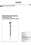
Operating Instructions
Vibrating level switch for granulated bulk
solids
VEGAVIB 61
- transistor (NPN/PNP)
Document ID: 29267
Contents
Contents
1
About this document
1.1 Function ........................................................................................................................... 4
1.2 Target group ..................................................................................................................... 4
1.3 Symbols used................................................................................................................... 4
2
For your safety
2.1 Authorised personnel ....................................................................................................... 5
2.2 Appropriate use ................................................................................................................ 5
2.3 Warning about incorrect use............................................................................................. 5
2.4 General safety instructions ............................................................................................... 5
2.5 Safety label on the instrument .......................................................................................... 6
2.6 CE conformity................................................................................................................... 6
2.7 SIL conformity .................................................................................................................. 6
2.8 Safety instructions for Ex areas ........................................................................................ 6
2.9 Environmental instructions ............................................................................................... 6
3
Product description
3.1 Configuration .................................................................................................................... 7
3.2 Principle of operation........................................................................................................ 7
3.3 Operation ......................................................................................................................... 8
3.4 Storage and transport....................................................................................................... 8
4
Mounting
4.1 General instructions ....................................................................................................... 10
4.2 Mounting instructions ..................................................................................................... 11
5
Connecting to power supply
5.1 Preparing the connection ............................................................................................... 14
5.2 Connection procedure .................................................................................................... 14
5.3 Wiring plan, single chamber housing.............................................................................. 15
5.4 Wiring plan - version IP 66/IP 68, 1 bar........................................................................... 17
6
Setup
6.1 General information ........................................................................................................ 18
6.2 Adjustment elements...................................................................................................... 18
6.3 Function chart ................................................................................................................ 19
7 Maintenanceandfaultrectification
7.1 Maintenance .................................................................................................................. 21
7.2 Rectify faults ................................................................................................................... 21
7.3 Exchanging the electronics module ................................................................................ 22
7.4 How to proceed if a repair is needed .............................................................................. 23
Dismount
8.1 Dismounting steps.......................................................................................................... 24
8.2 Disposal ......................................................................................................................... 24
9
Supplement
9.1 Technical data ................................................................................................................ 25
9.2 Dimensions .................................................................................................................... 28
2
VEGAVIB 61 • - transistor (NPN/PNP)
29267-EN-140625
8
Contents
Supplementary documentation
Information:
Supplementary documents appropriate to the ordered version come
withthedelivery.Youcanfindthemlistedinchapter"Product description".
29267-EN-140625
Instructions manuals for accessories and replacement parts
Tip:
ToensurereliablesetupandoperationofyourVEGAVIB61,weoffer
accessories and replacement parts. The corresponding documentations are:
•
•
•
31086 - External housing - VEGAVIB
30172 - Electronics module VEGAVIB series 60
34296 - Protective cover
Editing status:2014-05-26
VEGAVIB 61 • - transistor (NPN/PNP)
3
1 About this document
1
About this document
1.1
Function
1.2
Target group
1.3
Symbols used
This operating instructions manual provides all the information you
need for mounting, connection and setup as well as important instructionsformaintenanceandfaultrectification.Pleasereadthisinformation before putting the instrument into operation and keep this manual
accessible in the immediate vicinity of the device.
This operating instructions manual is directed to trained specialist
personnel. The contents of this manual should be made available to
these personnel and put into practice by them.
Information, tip, note
This symbol indicates helpful additional information.
Caution: If this warning is ignored, faults or malfunctions can result.
Warning: If this warning is ignored, injury to persons and/or serious
damage to the instrument can result.
Danger: If this warning is ignored, serious injury to persons and/or
destruction of the instrument can result.
Ex applications
This symbol indicates special instructions for Ex applications.
•
→
1
SIL applications
This symbol indicates instructions for functional safety which must be
particularly taken into account for safety-relevant applications.
List
The dot set in front indicates a list with no implied sequence.
Action
This arrow indicates a single action.
Sequence of actions
Numbers set in front indicate successive steps in a procedure.
Battery disposal
This symbol indicates special information about the disposal of batteries and accumulators.
29267-EN-140625
4
VEGAVIB 61 • - transistor (NPN/PNP)
2 For your safety
2
2.1
For your safety
Authorised personnel
All operations described in this operating instructions manual must
be carried out only by trained specialist personnel authorised by the
plant operator.
During work on and with the device the required personal protective
equipment must always be worn.
2.2
Appropriate use
The VEGAVIB 61 is a sensor for point level detection.
Youcanfinddetailedinformationabouttheareaofapplicationin
chapter"Product description".
Operational reliability is ensured only if the instrument is properly
usedaccordingtothespecificationsintheoperatinginstructions
manual as well as possible supplementary instructions.
For safety and warranty reasons, any invasive work on the device
beyond that described in the operating instructions manual may be
carried out only by personnel authorised by the manufacturer. Arbitraryconversionsormodificationsareexplicitlyforbidden.
2.3
Warning about incorrect use
2.4
General safety instructions
Inappropriate or incorrect use of the instrument can give rise to
application-specifichazards,e.g.vesseloverfillordamagetosystem
components through incorrect mounting or adjustment.
This is a state-of-the-art instrument complying with all prevailing
regulations and guidelines. The instrument must only be operated in a
technicallyflawlessandreliablecondition.Theoperatorisresponsible
for the trouble-free operation of the instrument.
During the entire duration of use, the user is obliged to determine the
compliance of the necessary occupational safety measures with the
current valid rules and regulations and also take note of new regulations.
The safety instructions in this operating instructions manual, the national installation standards as well as the valid safety regulations and
accident prevention rules must be observed by the user.
29267-EN-140625
For safety and warranty reasons, any invasive work on the device
beyond that described in the operating instructions manual may be
carried out only by personnel authorised by the manufacturer. Arbitraryconversionsormodificationsareexplicitlyforbidden.
The safety approval markings and safety tips on the device must also
be observed.
VEGAVIB 61 • - transistor (NPN/PNP)
5
2 For your safety
2.5
Safety label on the instrument
2.6
CE conformity
2.7
SIL conformity
2.8
Safety instructions for Ex areas
2.9
Environmental instructions
The safety approval markings and safety tips on the device must be
observed.
ThisdevicefulfillsthelegalrequirementsoftheapplicableECguidelines.ByattachingtheCEmark,VEGAprovidesaconfirmationof
successfultesting.YoucanfindtheCEconformitydeclarationinthe
downloadareaof"www.vega.com".
VEGAVIB 61 meets the requirements of functional safety according
to IEC 61508. Further information is available in the Safety Manual
"VEGAVIB series 60".
PleasenotetheEx-specificsafetyinformationforinstallationandoperation in Ex areas. These safety instructions are part of the operating
instructions manual and come with the Ex-approved instruments.
Protection of the environment is one of our most important duties.
That is why we have introduced an environment management system
with the goal of continuously improving company environmental protection.Theenvironmentmanagementsystemiscertifiedaccording
to DIN EN ISO 14001.
Pleasehelpusfulfillthisobligationbyobservingtheenvironmental
instructions in this manual:
•
•
Chapter"Packaging, transport and storage"
Chapter"Disposal"
29267-EN-140625
6
VEGAVIB 61 • - transistor (NPN/PNP)
3 Product description
3
Product description
3.1 Configuration
Scope of delivery
The scope of delivery encompasses:
Constituent parts
The VEGAVIB 61 consists of the components:
•
•
•
•
•
VEGAVIB 61 point level switch
Documentation
– this operating instructions manual
– SafetyManual"Functional safety (SIL)"(optional)
– Supplementaryinstructionsmanual"Plug connector for level
sensors"(optional)
– Ex-specific"Safety instructions"(withExversions)
– ifnecessary,furthercertificates
Housing cover
Housing with electronics
Processfittingwithvibratingrod
1
2
3
Fig. 1: VEGAVIB 61 - with plastic housing
1 Housing cover
2 Housing with electronics
3 Processfitting
Type label
Thetypelabelcontainsthemostimportantdataforidentificationand
use of the instrument:
•
•
•
•
•
Article number
Serial number
Technical data
Article numbers, documentation
SILidentification(withSILratingexworks)
29267-EN-140625
With the serial number, you can access the delivery data of the instrument via www.vega.com,"VEGA Tools"and"serial number search".
Inadditiontothetypelabeloutside,youcanalsofindtheserialnumber on the inside of the instrument.
Application area
3.2
Principle of operation
VEGAVIB 61 is a point level sensor with vibrating rod for level detection.
It is designed for industrial use in all areas of process technology and
is preferably used for bulk solids.
VEGAVIB 61 • - transistor (NPN/PNP)
7
3 Product description
Typicalapplicationsareoverfillanddryrunprotection.Thankstoits
simple and robust measuring system, VEGAVIB 61 is virtually unaffected by the chemical and physical properties of the bulk solid.
It also works when subjected to strong external vibrations or changing
products.
Solid detection in water
If VEGAVIB 61 was ordered for solid detection in water, the vibrating
rod is calibrated to the density of water. If covered by water (density:
1g/cm³/0.036lbs/in)VEGAVIB61signals"uncovered".Onlyifthe
vibrating element is also covered with solids (e.g. sand, sludge, gravel
etc.)willthesensorsignal"covered".
Function monitoring
The electronics module of VEGAVIB 61 monitors continuously the
following criteria:
•
•
Correct vibrating frequency
Linebreaktothepiezodrive
If a malfunction is detected or in case of power failure, the electronics
takesonadefinedswitchingcondition,i.e.theoutputisopen(safe
state).
Functional principle
Thevibratingrodispiezoelectricallyenergisedandvibratesatits
mechanicalresonancefrequencyofapprox.360Hz.Whenthevibrating rod is submerged in the product, the vibration amplitude changes.
This change is detected by the integrated electronics module and
converted into a switching command.
Voltage supply
VEGAVIB 61 is a compact instrument, i.e. it can be operated without
external evaluation system. The integrated electronics evaluates the
level signal and outputs a switching signal. With this switching signal,
a connected device can be operated directly (e.g. a warning system,
a pump etc.).
Thedataforpowersupplyarespecifiedinchapter"Technical data".
3.3
Operation
With the factory setting, products with a density of > 0.05 g/cm³
(0.002 lbs/in³) can be measured. It is possible to adapt the instrument
for products with lower density > 0.02 g/cm³ (0.0007 lbs/in³).
Ontheelectronicsmoduleyouwillfindthefollowingdisplayand
adjustment elements:
•
•
•
8
3.4
Storage and transport
Your instrument was protected by packaging during transport. Its
capacity to handle normal loads during transport is assured by a test
based on ISO 4180.
VEGAVIB 61 • - transistor (NPN/PNP)
29267-EN-140625
Packaging
Signal lamp for indication of the switching condition (green/red)
Potentiometer for adaptation to the product density
Mode switch for selecting the switching condition (min./max.)
3 Product description
The packaging of standard instruments consists of environmentfriendly, recyclable carton material. The sensing element is additionally protected with a cardboard cover. For special versions, PE foam or
PE foil is also used. Please dispose of the packaging material through
specialised recycling companies.
Transport
Transport must be carried out in due consideration of the notes on the
transport packaging. Nonobservance of these instructions can cause
damage to the device.
Transport inspection
The delivery must be checked for completeness and possible transit
damage immediately at receipt. Ascertained transit damage or concealed defects must be appropriately dealt with.
Storage
Up to the time of installation, the packages must be left closed and
stored according to the orientation and storage markings on the
outside.
Unless otherwise indicated, the packages must be stored only under
the following conditions:
•
Not in the open
Dry and dust free
Not exposed to corrosive media
Protected against solar radiation
Avoiding mechanical shock and vibration
Storageandtransporttemperatureseechapter"Supplement Technical data - Ambient conditions"
Relative humidity 20 … 85 %
29267-EN-140625
Storage and transport
temperature
•
•
•
•
•
•
VEGAVIB 61 • - transistor (NPN/PNP)
9
4 Mounting
4
4.1
Mounting
General instructions
Suitability for the process Make sure that all parts of the instrument coming in direct contact
conditions
with the process, especially the sensor element, process seal and
processfitting,aresuitablefortheexistingprocessconditions,such
as process pressure, process temperature as well as the chemical
properties of the medium.
Youcanfindthespecificationsinchapter"Technical data"andonthe
nameplate.
Switching point
In general, VEGAVIB 61 can be installed in any position. The instrument only has to be mounted in such a way that the vibrating element
is at the height of the desired switching point.
Moisture
Usetherecommendedcables(seechapter"Connecting to power
supply")andtightenthecablegland.
You can give your instrument additional protection against moisture
penetration by leading the connection cable downward in front of the
cableentry.Rainandcondensationwatercanthusdrainoff.Thisapplies mainly to outdoor mounting as well as installation in areas where
high humidity is expected (e.g. through cleaning processes) or on
cooled or heated vessels.
Fig. 2: Measures against moisture penetration
Transport
Do not hold VEGAVIB 61 on the vibrating element. Especially with
flangeandtubeversions,thesensorcanbedamagedbytheweight
of the instrument.
Remove the protective cover just before mounting.
Pressure/Vacuum
Theprocessfittingmustbesealedifthereisgaugeorlowpressurein
the vessel. Before use, check if the seal material is resistant against
the measured product and the process temperature.
Handling
10
The vibrating level switch is a measuring instrument and must be
treated accordingly. Bending the vibrating element will destroy the
instrument.
VEGAVIB 61 • - transistor (NPN/PNP)
29267-EN-140625
Themax.permissiblepressureisspecifiedinchapter"Technical
data"oronthetypelabelofthesensor.
4 Mounting
Warning:
The housing must not be used to screw the instrument in! Applying
tightening force can damage internal parts of the housing.
Use the hexagon above the thread for screwing in.
4.2
Mounting instructions
Socket
The vibrating element should protrude into the vessel to avoid
buildup.Forthatreason,avoidusingmountingbossesforflanges
andscrewedfittings.Thisappliesparticularlytousewithadhesive
products.
Filling opening
Mount the instrument in such a way that the vibrating rod does not
protrudedirectlyintothefillingstream.
a.
b.
20°
Fig. 3: Horizontal installation
a
b
Protective sheet
Concave protective sheet for abrasive solids
If such an installation location should be necessary, mount a suitable
protective sheet above or in front of the vibrating element, see illustration"a").
Inabrasivesolids,mountingaccordingtoillustration"b"hasproven.
A spout forms in the concave protective sheet preventing wear of the
protective sheet.
29267-EN-140625
Material cone
In silos for bulk solids, material cones can form and change the
switching point. Please keep this in mind when installing the sensor
in the vessel. We recommend selecting an installation location where
the vibrating rod detects an average value of the material cone.
The vibrating rod must be mounted in a way that takes the arrangementofthefillingandemptyingaperturesintoaccount.
To compensate measurement errors caused by the material cone in
cylindrical vessels, the sensor must be mounted at a distance of d/6
from the vessel wall.
VEGAVIB 61 • - transistor (NPN/PNP)
11
4 Mounting
d
6
d
6
d
d
d
6
Fig. 4: Filling and emptying centred
1
d
2
3
1
2
3
Horizontal installation
12
VEGAVIB 61
Discharge opening
Filling opening
To achieve a very precise switching point, you can install VEGAVIB 61
horizontally.However,iftheswitchingpointcanhaveatoleranceofa
VEGAVIB 61 • - transistor (NPN/PNP)
29267-EN-140625
Fig. 5: Filling in the centre, emptying laterally
4 Mounting
few centimeters, we recommend mounting VEGAVIB 61 approx. 20°
inclined to the vessel bottom to avoid buildup.
20°
Fig. 6: Horizontal installation
Inflowingmedium
IfVEGAVIB61ismountedinthefillingstream,unwantedfalsemeasurement signals can be generated. For this reason, mount VEGAVIB
61atapositioninthevesselwherenodisturbances,e.g.fromfilling
openings, agitators, etc., can occur.
Baffleprotectionagainst
falling rocks
In applications such as grit chambers or settling basins for coarse
sediments, the vibrating element must be protected against damage
withasuitablebaffle.
> 120 mm
(> 4.7")
Thisbafflemustbemanufacturedbyyou.
29267-EN-140625
> 125 mm
(> 5")
Fig.7:Baffleforprotectionagainstmechanicaldamage
VEGAVIB 61 • - transistor (NPN/PNP)
13
5 Connecting to power supply
5
Note safety instructions
Take note of safety
instructions for Ex
applications
Voltage supply
Connecting to power supply
5.1
Preparing the connection
Always keep in mind the following safety instructions:
•
Connect only in the complete absence of line voltage
Inhazardousareasyoumusttakenoteoftherespectiveregulations,
conformityandtypeapprovalcertificatesofthesensorsandpower
supply units.
Connect the operating voltage according to the following diagrams.
Take note of the general installation regulations. As a rule, connect
VEGAVIB 61 to vessel ground (PA), or in case of plastic vessels,
to the next ground potential. On the side of the instrument housing
there is a ground terminal between the cable entries. This connection
servestodrainoffelectrostaticcharges.InExapplications,theinstallationregulationsforhazardousareasmustbegivenpriority.
Thedataforpowersupplyarespecifiedinchapter"Technical data".
Connection cable
The instrument is connected with standard two-wire cable without
screen. If electromagnetic interference is expected which is above the
test values of EN 61326 for industrial areas, screened cable should
be used.
Use cable with round cross-section. A cable outer diameter of
5…9mm(0.2…0.35in)ensuresthesealeffectofthecablegland.
Ifyouareusingcablewithadifferentdiameterorcross-section,
exchange the seal or use a suitable cable gland.
Inhazardousareas,onlyuseapprovedcableconnectionsforVEGAVIB 61.
Connection cable
for Ex applications
Take note of the corresponding installation regulations for Ex applications.
Cover all housing openings conforming to standard according to
EN 60079-1.
5.2
Connection procedure
With Ex instruments, the housing cover may only be opened if there is
no explosive atmosphere present.
Proceed as follows:
1. Unscrew the housing cover
2. Loosen compression nut of the cable entry gland
3. Remove approx. 10 cm (4 in) of the cable mantle, strip approx.
1 cm (0.4 in) of insulation from the ends of the individual wires
5. Lift the opening levers of the terminals with a screwdriver (see
following illustration)
14
VEGAVIB 61 • - transistor (NPN/PNP)
29267-EN-140625
4. Insert the cable into the sensor through the cable entry
5 Connecting to power supply
Fig. 8: Connection steps 5 and 6
6. Insert the wire ends into the open terminals according to the wiring plan
7. Press down the opening levers of the terminals, you will hear the
terminal spring closing
8. Check the hold of the wires in the terminals by lightly pulling on
them
9. Tighten the compression nut of the cable entry gland. The seal
ring must completely encircle the cable
10. If necessary, carry out a fresh adjustment
11. Screw the housing cover back on
Theelectricalconnectionisfinished.
5.3
Wiring plan, single chamber housing
29267-EN-140625
The following illustrations apply to the non-Ex as well as to the Ex-d
version.
VEGAVIB 61 • - transistor (NPN/PNP)
15
5 Connecting to power supply
Housing overview
5
5
1
5
5
2
3
4
Fig. 9: Material versions, single chamber housing
1
2
3
4
5
Wiring plan
Plastic (not with EEx d)
Aluminium
Stainless steel (not with EEx d)
Stainless steel, electropolished (not with EEx d)
Filter element for pressure compensation or blind plug with version IP 66/
IP 68, 1 bar (not with EEx d)
We recommend connecting VEGAVIB 61 in such a way that the
switching circuit is open when there is a level signal, line break or
failure (safe state).
The instrument is used to control relays, contactors, magnet valves,
warning lights, horns as well as PLC inputs.
Caution:
There is no reverse polarity protection. Take note of the polarity of the
output lines.
1
29267-EN-140625
Fig. 10: Wiring plan
1
16
Voltage supply
VEGAVIB 61 • - transistor (NPN/PNP)
5 Connecting to power supply
+
-
1 2 3 4
+
-
Fig. 11: NPN action
+
-
1 2 3 4
+
-
Fig. 12: PNP action
Wire assignment, connection cable
5.4
Wiring plan - version IP 66/IP 68, 1 bar
1
2
3
4
5
Fig. 13: Wire assignment connection cable. The numbers of the wires correspond to the terminals of the instrument.
brown (+) voltage supply
White
Yellow
blue (-) voltage supply
Shielding
29267-EN-140625
1
2
3
4
5
VEGAVIB 61 • - transistor (NPN/PNP)
17
6 Setup
6
Setup
6.1
General information
Thefiguresinbracketsrefertothefollowingillustrations.
Function/Configuration
Ontheelectronicsmoduleyouwillfindthefollowingdisplayand
adjustment elements:
•
•
•
Potentiometer for adaptation to the product density (1)
DIL switch for mode adjustment - min./max. (2)
Signal lamp (5)
Note:
As a rule, always set the mode with mode switch (2) before starting
the setup of VEGAVIB 61. The switching output will change if you set
the mode switch (2) afterwards. This could possibly trigger other connected instruments or devices.
Electronics and terminal
compartment
6.2
Adjustment elements
1
5
2
4
3
Fig. 14: Electronics and connection compartment - transistor output
1
2
3
4
5
18
With the potentiometer you can adapt the switching point to the solid.
Itisalreadypresetandmustonlybemodifiedinspecialcases.
As a default setting, the potentiometer of VEGAVIB 61 is set to
the complete right position (> 0.3 g/cm³/0.011 lbs/in³). In very light
solids you have to turn the potentiometer to the complete left position (0.02 … 0.1 g/cm³ or 0.0007 … 0.0036 lbs/in³). By doing this,
VEGAVIB 61 • - transistor (NPN/PNP)
29267-EN-140625
Switching point adaptation (1)
Potentiometer for switching point adaptation
DIL switch for mode adjustment
Ground terminal
Connection terminals
Control lamp
6 Setup
VEGAVIB 61 will be more sensitive and light solids can be detected
more reliably.
For instruments detecting solids in water, these settings are not
applicable. The switching point adaptation is preset and must not be
changed.
Mode adjustment (2)
With the mode switch (min./max.) you can change the switching status of the transistor output. You can set the required mode according
tothe"Function chart"(max.-max.detectionoroverflowprotection,
min. - min. detection or dry run protection).
We recommend connecting according to the idle current principle
(switching output is opened when the switching point is reached) because the transistor output takes on the same (safe) state if a failure
is detected.
Signal lamp (5)
Control lamp for indication of the switching status
•
•
•
Green = Output closed
Red = Output open
red(flashing)=failure
6.3
Function chart
The following chart provides an overview of the switching conditions
depending on the set mode and the level.
Level
Switching status Control lamp
Mode max.
closed
Mode max.
open
Mode min.
closed
Mode min.
open
Failure of the sup- any
ply voltage
open
Overflowprotection
Green
Overflowprotection
Red
Dry run protection
Green
29267-EN-140625
Dry run protection
Red
(min./max. mode)
VEGAVIB 61 • - transistor (NPN/PNP)
19
6 Setup
Fault
Level
Switching status Control lamp
any
open
flashesred
29267-EN-140625
20
VEGAVIB 61 • - transistor (NPN/PNP)
7Maintenanceandfaultrectification
7 Maintenanceandfaultrectification
7.1
Maintenance
7.2
Rectify faults
If the instrument is used properly, no special maintenance is required
in normal operation.
Reaction when malfunctions occur
The operator of the system is responsible for taking suitable measures to rectify faults.
Failure reasons
VEGAVIB61offersmaximumreliability.Nevertheless,faultscanoccur during operation. These may be caused by the following, e.g.:
•
•
•
•
Sensor
Process
Voltage supply
Signal processing
Faultrectification
Thefirstmeasuretobetakenistochecktheoutputsignal.Inmany
cases,thecausescanbedeterminedthiswayandthefaultsrectified.
24 hour service hotline
Should these measures not be successful, please call in urgent cases
the VEGA service hotline under the phone no. +49 1805 858550.
Checking the switching
signal
Thehotlineismanned7daysaweekround-the-clock.Sinceweoffer
this service worldwide, the support is only available in the English
language. The service is free, only standard call charges are incurred.
Error
Cause
Rectification
VEGAVIB 61 signals
"covered"withoutbeing
submerged(overfillprotection)
Operating voltage too low
Check operating voltage
Electronics defective
Press the mode switch. If the instrument then changes
the mode, the vibrating element may be covered with
buildup or mechanically damaged. Should the switching function in the correct mode still be faulty, return the
instrument for repair.
VEGAVIB61signals"uncovered"whenbeing
submerged (dry run protection)
Press the mode switch. If the instrument then does not
change the mode, the electronics module may be defective. Exchange the electronics module.
Unfavourable installation
location
Mount the instrument at a location in the vessel where
nodeadzonesormoundscanform.
Buildup on the vibrating el- Check the vibrating element and the sensor if there is
ement
buildup and remove it.
29267-EN-140625
Wrong mode selected
VEGAVIB 61 • - transistor (NPN/PNP)
Setthecorrectmodewiththemodeswitch(overflow
protection, dry run protection). Wiring should be carried
out according to the idle current principle.
21
7Maintenanceandfaultrectification
Error
Cause
Rectification
Signallampflashesred
Error on the vibrating element
Check if the vibrating element is damaged or extremely corroded.
Interference on the electronics module
Exchanging the electronics module
instrument defective
Exchange the instrument or send it in for repair
Reaction after fault rectification
Depending on the reason for the fault and the measures taken, the
stepsdescribedinchapter"Set up"mayhavetobecarriedoutagain.
7.3
Exchanging the electronics module
In general, all electronics modules of series VB60 can be interchanged.Ifyouwanttouseanelectronicsmodulewithadifferent
signal output, you can download the corresponding operating instructions manual from our homepage under Downloads.
With Ex-d instruments, the housing cover may only be opened if there
is no explosive atmosphere present.
Proceed as follows:
1. Switchoffpowersupply
2. Unscrew the housing cover
3. Lift the opening levers of the terminals with a screwdriver
4. Pull the connection cables out of the terminals
5. Loosenthetwoscrewswithascrewdriver(TorxsizeT10orslot
4)
1
2
Fig. 25: Loosening the holding screws
1
2
Electronics module
Screws (2 pcs.)
6. Pull out the old electronics module
22
VEGAVIB 61 • - transistor (NPN/PNP)
29267-EN-140625
7. Compare the new electronics module with the old one. The type
label of the electronics module must correspond to that of the old
electronics module. This applies particularly to instruments used
inhazardousareas.
7Maintenanceandfaultrectification
8. Compare the settings of the two electronics modules. Set the
adjustment elements of the new electronics module to the same
setting of the old one.
Information:
Make sure that the housing is not rotated during the electronics exchange.Otherwisetheplugmaybeinadifferentpositionlater.
9. Insert the electronics module carefully. Make sure that the plug is
in the correct position.
10. Screw in and tighten the two holding screws with a screwdriver
(TorxsizeT10orPhillips4)
11. Insert the wire ends into the open terminals according to the wiring plan
12. Press down the opening levers of the terminals, you will hear the
terminal spring closing
13. Check the hold of the wires in the terminals by lightly pulling on
them
14. Check cable gland on tightness. The seal ring must completely
encircle the cable.
15. Screw the housing cover back on
Theelectronicsexchangeisnowfinished.
7.4
How to proceed if a repair is needed
Youcanfindarepairformaswellasdetailedinformationonhowto
proceed at www.vega.com/downloadsand"Formsandcertificates".
By doing this you help us carry out the repair quickly and without having to call back for needed information.
If a repair is necessary, please proceed as follows:
•
•
•
29267-EN-140625
•
Printandfilloutoneformperinstrument
Clean the instrument and pack it damage-proof
Attach the completed form and, if need be, also a safety data
sheet outside on the packaging
Please contact the agency serving you to get the address for
thereturnshipment.Youcanfindtheagencyonourhomepage
www.vega.com.
VEGAVIB 61 • - transistor (NPN/PNP)
23
8 Dismount
8
8.1
Dismount
Dismounting steps
Warning:
Before dismounting, be aware of dangerous process conditions such
as e.g. pressure in the vessel, high temperatures, corrosive or toxic
products etc.
Takenoteofchapters"Mounting"and"Connecting to power supply"
and carry out the listed steps in reverse order.
With Ex instruments, the housing cover may only be opened if there is
no explosive atmosphere present.
8.2
Disposal
The instrument consists of materials which can be recycled by specialised recycling companies. We use recyclable materials and have
designed the parts to be easily separable.
WEEE directive 2002/96/EG
This instrument is not subject to the WEEE directive 2002/96/EG and
the respective national laws. Pass the instrument directly on to a specialised recycling company and do not use the municipal collecting
points. These may be used only for privately used products according
to the WEEE directive.
Correctdisposalavoidsnegativeeffectsonhumansandtheenvironment and ensures recycling of useful raw materials.
Materials:seechapter"Technical data"
If you have no way to dispose of the old instrument properly, please
contact us concerning return and disposal.
29267-EN-140625
24
VEGAVIB 61 • - transistor (NPN/PNP)
9 Supplement
9
9.1
Supplement
Technical data
General data
Material 316L corresponds to 1.4404 or 1.4435
Materials, wetted parts
Ʋ Processfitting-thread
316L
Ʋ Process seal
Klingersil C-4400
Ʋ Processfitting-flange
Ʋ Vibrating rod
316L, 318 S13 (1.4462)
Ʋ Extension tube ø 29 mm (1.14 in)
316L
Ʋ Plastic housing
plastic PBT (Polyester)
Materials, non-wetted parts
Ʋ Aluminium die-casting housing
Ʋ Stainless steel housing - precision
casting
Ʋ Stainless steel housing, electropolished
Ʋ Seal between housing and housing
cover
Ʋ Light guide in housing cover (plastic)
Ʋ Ground terminal
Processfittings
Ʋ Pipe thread, cylindrical (DIN 3852-A)
Ʋ American pipe thread, conical
(ASME B1.20.1)
Instrument weight (depending on processfitting)
Aluminium die-casting AlSi10Mg, powder-coated - basis:
Polyester
316L
316L
NBR (stainless steel housing, precision casting), silicone
(aluminium/plastic housing; stainless steel housing,
electropolished)
PMMA (Makrolon)
316L
G1, G1½
1 NPT, 1½ NPT
0.8 … 4 kg (0.18 … 8.82 lbs)
Max. lateral load
400 N (90 lbf)
Output variable
Output
Floating transistor output, permanently shortcircuit-proof
Switching voltage
< 55 V DC
Load current
Blocking current
Modes (switchable)
29267-EN-140625
316L
Switching delay
Ʋ When immersed
Ʋ When laid bare
VEGAVIB 61 • - transistor (NPN/PNP)
< 400 mA
< 100 µA
min./max.
0.5 s
1s
25
9 Supplement
Ambient conditions
Ambient temperature on the housing
-40 … +80 °C (-40 … +176 °F)
Storage and transport temperature
-40 … +80 °C (-40 … +176 °F)
Process conditions
Measured variable
Limit level of solids
Process pressure
-1 … 16 bar/-100 … 1600 kPa (-14.5 … 232 psig)
2
16 bar
(232psi)
6 bar
(87psi)
0°C
(32°F)
-50°C
(-58°F)
1
2
Process temperature
Process pressure
1
50°C
(122°F)
100°C
(212°F)
150°C
(302°F)
200°C
(392°F)
250°C
(482°F)
Fig. 26: Process pressure - Process temperature
VEGAVIB 61 of 316L
-50 … +150 °C (-58 … +302 °F)
Processtemperature(threadorflange
temperature) with temperature adapter
(option)
-50 … +250 °C (-58 … +482 °F)
2
3
80°C
(176°F)
40°C
(104°F)
-50°C
(-58°F)
1
2
3
50°C
(122°F)
100°C
(212°F)
150°C
(302°F)
200°C
(392°F)
250°C
(482°F)
Fig. 27: Ambient temperature - Process temperature
Granularsize
> 0.05 g/cm³ (0.002 lbs/in³)
> 0.02 g/cm³ (0.0007 lbs/in³)
no limitation1)
max. 20 mm (0.8 in) with product density < 0.05 g/cm³ (0.002 lbs/in³).
VEGAVIB 61 • - transistor (NPN/PNP)
29267-EN-140625
Ʋ Standard
Ʋ adjustable
26
-40°C
(-40°F)
1
Process temperature
Ambient temperature
Temperature range with temperature adapter
Density
1)
0°C
(32°F)
9 Supplement
Electromechanical data - version IP 66/IP 67 and IP 66/IP 68; 0.2 bar
Cable entry/plug2)
Ʋ Single chamber housing
– 1 x cable gland M20 x 1.5 (cable: ø 5 … 9 mm), 1 x
blind plug M20 x 1.5
or:
– 1 x closing cap ½ NPT, 1 x blind plug ½ NPT
or:
Spring-loaded terminals
– 1␣xplug(dependingontheversion),1␣xblindstopper
M20␣x␣1.5
for wire cross-section up to 1.5 mm² (AWG 16)
Electromechanical data - version IP 66/IP 68 (1 bar)
Cable entry
Ʋ Single chamber housing
Connection cable
Ʋ Wire cross-section
Ʋ Wire resistance
Ʋ Tensile strength
Ʋ Standard length
Ʋ Max. length
Ʋ Min. bending radius
Ʋ Diameter approx.
Ʋ Colour - standard PE
Ʋ Colour - standard PUR
Ʋ Colour - Ex-version
Adjustment elements
Mode switch
Ʋ Min.
Ʋ Max.
Voltage supply
Operating voltage
29267-EN-140625
Power consumption
Electrical protective measures
Protection rating
Ʋ Plastic housing
2)
– 1 x IP 68 cable gland M20 x 1.5; 1 x blind plug
M20 x 1.5
or:
– 1 x closing cap ½ NPT, 1 x blind plug ½ NPT
> 0.5 mm² (AWG 20)
<0.036Ω/m(0.011Ω/ft)
< 1200 N (270 lbf)
5 m (16.4 ft)
1000 m (3280 ft)
25 mm (0.984 in) with 25 °C (77 °F)
8 mm (0.315 in)
Black
Blue
Blue
Min. detection or dry run protection
Max.detectionoroverflowprotection
10 … 55 V DC
max. 0.5 W
IP 66/IP 67 (NEMA 4X)
Depending on the version M12 x 1, according to ISO 4400, Harting, 7/8" FF.
VEGAVIB 61 • - transistor (NPN/PNP)
27
9 Supplement
Ʋ Aluminium and stainless steel standard
Ʋ Aluminium and stainless housing
(optionally available)
Overvoltage category
IP 66/IP 68 (0.2 bar), NEMA 6P3)
IP 66/IP 68 (1 bar) NEMA 6P
III
Protection class
II
Approvals
Instrumentswithapprovalscanhavedifferenttechnicalspecificationsdependingontheversion.
For that reason the associated approval documents of these instruments have to be carefully
noted. They are part of the delivery or can be downloaded under www.vega.comvia"VEGA Tools"
and"Instrument search"aswellasvia"Downloads"and"Approvals".
9.2
Dimensions
Housing in protection IP 66/IP 67 and IP 66/IP 68; 0.2 bar
1
M20x1,5/
½ NPT
116 mm (4.57")
ø 86 mm (3.39")
M20x1,5
M20x1,5/
½ NPT
M20x1,5/
½ NPT
2
~ 116 mm (4.57")
117 mm (4.61")
112 mm (4.41")
112 mm (4.41")
M20x1,5/
½ NPT
~ 69 mm
(2.72")
ø 79 mm
(3.11")
~ 59 mm
(2.32")
ø 80 mm
(3.15")
~ 69 mm
(2.72")
ø 79 mm
(3.03")
3
4
Fig. 28: Housing versions in protection IP 66/IP 67 and IP 66/IP 68; 0.2 bar
1
2
3
4
28
A suitable cable is the prerequisite for maintaining the protection rating.
VEGAVIB 61 • - transistor (NPN/PNP)
29267-EN-140625
3)
Plastic housing
Stainless steel housing, electropolished
Stainless steel housing, precision casting
Aluminium housing
9 Supplement
Housing in protection IP 66/IP 68 (1 bar)
~ 150 mm
(5.91")
ø 84 mm
(3.31")
~ 103 mm
(4.06")
117 mm
(4.61")
116 mm
(4.57")
ø 77 mm
(3.03")
M20x1,5
M20x1,5
M20x1,5
1
2
Fig. 29: Housing versions with protection rating IP 66/IP 68 (1 bar)
Stainless steel housing, precision casting
Aluminium housing
20 mm
(0.79")
25 mm
(0.98")
1
2
G1
125 mm
(4.92")
160 mm
(6.3")
ø 29 mm
(1.14")
ø16 mm
(0.63")
29267-EN-140625
Fig. 30: VEGAVIB 61, threaded version G1 (DIN ISO 228/1)
VEGAVIB 61 • - transistor (NPN/PNP)
29
G1½
ø 29 mm
(1.14")
125 mm
(4.92")
162 mm
(6.38")
22 mm
(0.87")
33 mm
(1.30")
9 Supplement
ø16 mm
(0.63")
178 mm
(7.01")
Fig. 31: VEGAVIB 61, threaded version G1½ (DIN ISO 228/1)
ø 34 mm
(1.34")
29267-EN-140625
Fig. 32: Temperature adapter
30
VEGAVIB 61 • - transistor (NPN/PNP)
9 Supplement
9.3
Industrial property rights
VEGA product lines are global protected by industrial property rights. Further information see
www.vega.com.
Only in U.S.A.: Further information see patent label at the sensor housing.
VEGA Produktfamilien sind weltweit geschützt durch gewerbliche Schutzrechte.
Nähere Informationen unter www.vega.com.
Les lignes de produits VEGA sont globalement protégées par des droits de propriété intellectuelle. Pour plus d'informations, on pourra se référer au site www.vega.com.
VEGA lineas de productos están protegidas por los derechos en el campo de la propiedad industrial. Para mayor información revise la pagina web www.vega.com.
Линии продукции фирмы ВЕГА защищаются по всему миру правами на интеллектуальную
собственность. Дальнейшую информацию смотрите на сайте www.vega.com.
VEGA系列产品在全球享有知识产权保护。
进一步信息请参见网站<www.vega.com。
9.4
Trademark
29267-EN-140625
All the brands as well as trade and company names used are property of their lawful proprietor/
originator.
VEGAVIB 61 • - transistor (NPN/PNP)
31
All statements concerning scope of delivery, application, practical use and operating conditions of the sensors and processing systems correspond to the information
available at the time of printing.
Subject to change without prior notice
© VEGA Grieshaber KG, Schiltach/Germany 2014
VEGA Grieshaber KG
Am Hohenstein 113
77761 Schiltach
Germany
Phone +49 7836 50-0
Fax +49 7836 50-201
E-mail: [email protected]
www.vega.com
29267-EN-140625
Printing date: