1
5 Connecting to the bus system
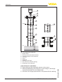
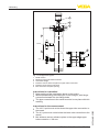
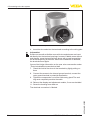
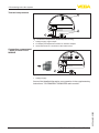
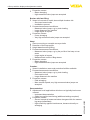
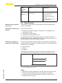
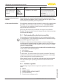
Fig. 14: Connection steps 5 and 6 - Double chamber housing
6. Insert the wire ends into the terminals according to the wiring plan
Information:
Solidcoresaswellasflexiblecoreswithwireendsleevesareinserteddirectlyintotheterminalopenings.Incaseofflexiblecoreswithout
end sleeves, press the terminal from above with a small screwdriver,
the terminal opening is then free. When the screwdriver is released,
the terminal closes again.
Youcanfindfurtherinformationonthemax.wirecross-sectionunder
"Technicaldata/Electromechanicaldata"
7. Check the hold of the wires in the terminals by lightly pulling on
them
8. Connect the screen to the internal ground terminal, connect the
outer ground terminal to potential equalisation
9. Tighten the compression nut of the cable entry gland. The seal
ring must completely encircle the cable
10. Reinsert the display and adjustment module, if one was installed
11. Screw the housing cover back on
Theelectricalconnectionisfinished.
36530-EN-140209
24
VEGAPULS 66 • Foundation Fieldbus