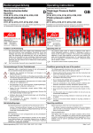
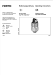
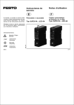
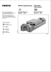
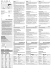
1
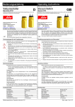
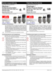
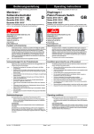
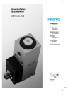
Einbau und Inbetriebnahme nur von qualifiziertem Fachpersonal, gemäß Bedienungsanleitung. Bedienungsanleitung Operating instructions Druck- oder Vakuumschalter Typ (V)PEV-W-...-LED-GH Pressure or vacuum switch Type (V)PEV-W-...-LED-GH Fitting and commissioning to be carried out by qualified personnel only in accordance with the operating instructions. Es bedeuten/Symbols: Warnung Warning, Caution Hinweis Note Zubehör Accessories 0503d 693 421 Recycling Recycling D/GB 1 (V)PEV-W-...-LED-GH Bedienteile und Anschlüsse 1 Füße zur Befestigung Klemmfuß für Schienenmontage (Zubehör) Durchgangsbohrungen zur Befestigung Aufnahme für Klemmfuß Druckluft- oder Vakuumanschlüsse Stellschraube zur Schaltpunkteinstellung (außen) Handhilfsbetätigung (innen) Nut für Bezeichnungsschilder Statusanzeige (gelb) Elektrischer Anschlußstecker Elektrische Anschluß-Klemmleiste Feet for fastening Clamping foot for fitting onto rail (accessories) Through holes for fastening Recess for clamping foot Connections for compressed air or vacuum Adjusting screw for setting the switching point (on outside) Manual override (on inside) Groove for designation sign Status LED (yellow) Electrical connection plug Electrical terminal strip 0503d © ª « ¬ ® ¯ ° ± ² ³ © ª « ¬ ® ¯ ° ± ² ³ Operating parts and connections « ³ ² ± ° ¯ ª © ® ¬ Bild 1/Fig. 1 D/GB 2 2 3 L F -... L R -... Bild 2/Fig. 2 C Bild 3/Fig. 3 0503d % m bar Funktion und Anwendung Function and application Der (V)PEV-... enthält eine Kammer mit einer Kräftewaage. An dieser Kräftewaage wirken auf der einen Seite Druckkräfte auf der anderen die Federkraft der Einstellfeder. Bei Erhöhung der Druck- oder Vakuumkräfte über die Federkraft hinaus, bewegt sich die Kräftewaage und schaltet einen elektrischen Schalter um. Der (V)PEV-.. ist als Schließer, Öffner oder Wechsler einsetzbar. Er dient zur Umwandlung pneumatischer Druckwerte in elektrische Signale, die für Steuerungs- oder Überwachungsfunktionen gebraucht werden. The (V)PEV-... contains a chamber with a force balance. Pressure forces act on one side of this force balance and the spring force of the setting spring acts on the other side. If the pressure or vacuum forces are increased to a level higher than the spring force, the force balance will move and actuate an electrical switch. The (V)PEV-... can be used as a normally-open, normally-closed or changeover switch. It serves for converting pneumatic pressure values into electrical signals which can then be used for control or monitor functions. Voraussetzungen für den Produkteinsatz Safety conditions Allgemeine, stets zu beachtende Hinweise für den ordnungsgemäßen und sicheren Einsatz des Produkts: These general conditions for the correct and safe use of the product must be observed at all times. • Halten Sie die angegebenen Grenzwerte ein (z. B. für Drücke, Kräfte, Temperaturen). • Please observe the limits (e.g. for pressures, forces, temperatures). • Sorgen Sie für ordungsgemäß aufbereitete Druckluft. • Please ensure that there is a supply of correctly prepared compressed air. D/GB 3 (V)PEV-W-...-LED-GH • Berücksichtigen Sie die vorherrschenden Umweltbedingungen. • Please observe the prevailing environmental conditions. • Beachten Sie die Vorschriften der Berufsgenossenschaft, des VDE, des Technischen Überwachungsvereins oder entsprechende nationale Bestimmungen. • Please comply with national and local safety laws and regulations. • Entfernen Sie alle Transportvorkehrungen wie Schutzwachs, Folien, Kappen, Kartonagen. • Remove all packaging such as protective wax, foils (polyamide), caps (polyethylene). Die Entsorgung der einzelnen Werkstoffe in Recycling-Sammelbehälter ist möglich. • Verwenden Sie das Produkt im Originalzustand ohne jegliche eigenmächtige Veränderung. 0503d The individual materials can be disposed of in recycling containers. • Use the product in its original condition without undertaking any unauthorized modifications. D/GB 4 5 a) 1) b) 2) Bild 4/Fig. 4 c) 3) Einbau Fitting mechanisch Mechanical 1. Wählen Sie die geeignete Befestigungsart: a) Durchgangsbohrungen im Gehäuse oder 1. Select a suitable fastening method: a) through holes in the housing or b) einschiebbare Füße mit Bohrung oder b) push-in feet with holes or c) Klemmfuß für G- oder H-Schienenmontage c) clamping foot for G or H-rail fitting 2. Befestigen Sie den (V)PEV-... an der vorgesehenen Stelle. 2. Fasten the (V)PEV-... at the position intended. Zum Bezeichen des (V)PEV-...: 3. Verwenden Sie Bezeichnungsschilder in der vorgesehenen Nut. In order to designate the (V)PEV-...: 3. Place signs in the groove intended. Bild 5/Fig. 5 0503d D/GB 5 (V)PEV-W-...-LED-GH VPEV-W-... PEV-W-... (A) 0,8 Nm pneumatisch Pneumatic • Verwenden Sie Verschraubungen der Größe M5 zum Aufstecken der Schlauchleitungen. • Use connections for the tubing of size M5. • Lassen Sie die Sechskant-Filterschraube des PEV-W-... (A) im anderen Anschluss (darf nicht verwendet werden) stets eingeschraubt. • Leave the hexagon filter screw with the PEV-W-... (A) screwed in the other connection (must not be used). Andernfalls gefährden Verschmutzungen die Funktionssicherheit. Otherwise dirt will impair the func-tional reliability. • Drehen Sie die Verschraubung in den entsprechenden Anschluss ein: • Screw in the corresponding air connection. Bild 7/Fig. 7 Vakuumschalter VPEV-W-... Druckschalter PEV-W-... Vacuum switch VPEV-W-... Pressure switch PEV-W-... Vakuumanschluss (V) Druckluftanschluss (P) Connection for vacuum (V) Connection for compressed air (P) Bild 6 Fig 6 Maximales Drehmoment: 0,8 Nm Maximum tightening torque of the M5 thread 0,8 Nm. The connections fit tightly without the need for an additional seal. Die Anschlüsse dichten ohne zusätzlichen Dichtring ab. 0503d D/GB 6 max. 0,3 Nm Bild 8/Fig. 8 elektrisch Electrical • Verwenden Sie für die elektrische Versorgung ausschließlich PELV-Stromkreise nach IEC/DIN EN 60204-1 (Protective Extra-Low Voltage, PELV). Berücksichtigen Sie zusätzlich die allgemeinen Anforderungen an PELVStromkreise gemäß der IEC/DIN EN 60204-1. • Use only PELV circuits as per IEC/DIN EN 60204-1 (Protective Extra-Low Voltage, PELV) for the electrical supply. Consider also the general requirements for PELV circuits in accordance with IEC/DIN EN 60204-1. • Verwenden Sie ausschließlich Stromquellen die eine sichere elektrische Trennung der Betriebs-spannung nach IEC/DIN EN 60204-1 gewährleisten. • Use power supplies which guarantee reliable electrical isolation of the operating voltage as per IEC/DIN EN 60204-1. Bei (V)PEV-W-S-... (Steckervariante): With (V)PEV-W-S-... (plug version): • Verwenden Sie für die Verkabelung eine Dose mit Kabel gemäß Kapitel "Zubehör". • Use a socket with cable for the cabling as mentioned in Chapter "Accessoires". • Verkabeln Sie den (V)PEV nach Bild 9 und 10/10a. • Connect the cables of the (V)PEV as shown in Fig. 9 and 10/10a. Bei Verwendung des Ausgangssignals (out) zur Ansteuerung von Ventilmagneten: If the output signal (out) is used for controlling valve solenoids: • Prüfen Sie die Notwendigkeit einer Schutzbeschaltung des (V)PEV-... gegen induktive Spannungsspitzen. • Check wether a special circuit is necessary to protect the (V)PEV-... against inductive voltage peaks. Bild 9/Fig. 9 (V)PEV-W-KL-... Bild 10/Fig. 10 (V)PEV-W-S-... + SIM-... + (-) (B N ) o u t 2 (WH) o u t 4 (B K) - (+) (B U ) Bild 10a/Fig. 10a 0503d D/GB 7 (V)PEV-W-...-LED-GH 5 24V DC Inbetriebnahme Commissioning 1. Bestromen Sie den (V)PEV-... mit Gleichstrom. 1. Apply direct current to the (V)PEV-... 2. Belüften Sie den Druckluftanschluß mit dem Druck, der als Schaltdruck benötigt wird oder evakuieren Sie den Vakuumanschluß mit dem Vakuum, das als Schaltvakuum benötigt wird. 2. Pressurize the compressed air connection with the pressure required as switching pressure or draw the air out of the vacuum connection with the vacuum required as switching vacuum. 3. Drehen Sie die Stellschraube gegen den Uhrzeigersinn, bis die gelbe LED leuchtet. 3. Turn the adjusting screw in an anti clockwise direction until the yellow LED lights up. 4. Vergleichen Sie den eingestellten Wert durch Verändern des anliegenden Drucks oder Vakuums mit den Vorgaben. 4. Check the value set by modifying the pressure or vacuum applied. Bei Bedarf: 5. Wiederholen Sie Ihre Einstellungen. If necesarry: 5. Repeat your settings. (V)PEV -... Bild 11/Fig. 11 P (V) Bild 12/Fig. 12 Bild 13/Fig. 13 OUT P (V) 0 Bild 14/Fig. 14 0503d bar D/GB 8 6 Bedienung und Betrieb Operation • Prüfen Sie die richtige Beschaltung Ihres (V)PEV-.... • Check the correct circuit function of the (V)PEV-.... Beschaltung als Schließer Beschaltung als Öffner Beschaltung als Wechsler gelbe LED leuchtet bei geschaltetem Ausgang 4 gelbe LED leuchtet bei geöffnetem Ausgang 2 gelbe LED leuchtet bei geschaltetem Ausgang 4 Circuit for normallyopen switch Yellow LED lights up when output 4 is switched Circuit for normallyclosed switch Yellow LED lights up when output 2 is switched Circuit for changeover switch Yellow LED lights up when output 4 is switched Bild 15 Fig. 15 Bei Druckausfall: If there is a drop in pressure, • Nutzen Sie die Möglichkeit der Handhilfsbetätigung. • use the manual override. Sie federt ohne Einrasten zurück. This does not lock and returns by spring force to its basic position. Bild 16/Fig. 16 7 Wartung und Pflege Maintenance and care Bei Verschmutzung: If dirty, • Reinigen Sie (V)PEV-.... • clean the (V)PEV-.... Zulässige Reinigungsmedien sind alle werkstoffschonenden Medien. 0503d You may use any cleaning agent which does not damage the switch. D/GB 9 (V)PEV-W-...-LED-GH 8 Ausbau und Reparatur Dismantling and repairs 1. Schalten Sie folgende Energiequellen ab: - Betriebsspannung - Druckluft - Vakuum. 1. Switch off the following sources of energy: - power supply - compressed air - vacuum 2. Trennen Sie die jeweiligen Anschlüsse vom (V)PEV-... 2. Unscrew the relevant connections. 3a. Bei Befestigung mit Schnappfuß auf G-Schiene: Ziehen Sie den (V)PEV-... folgender maßen von der Schiene ab: - langsam - kräftig - verkippfrei. 3a. For fastening with clamping foot on G-rail: Remove the (V)PEV-... from the rail as follows: - slowly - with force - without tilting 3b. Bei Befestigung mit Schnappfuß auf H-Schiene: Drücken Sie mit einem Schlitzschraubendreher gegen die Zunge des Schnappfußes. 3b. For fastening with clamping foot on H-rail: Press against the tongue of the clamping foot with a slotted-head screwdriver. Bild 17/Fig. 17 Bild 18/Fig. 18 Bild 19/Fig. 19 0503d D/GB 10 9 Zubehör Dose mit Kabel Stecknippel Klemmfuß Montageplatte für Montagerahmen Bezeichnungsschilder Typ Typ Typ Typ Typ Typ Typ Typ SIM-K-4-... SIM-M8-4-... N-... CK-... QSM-... PENV-BGH APL-2N-PENV BZ-NUM Bild 20 Accessories Socket with cable Plug nipple Clamping foot Plate for fitting frame Designation signs Typ SIM-K-4-... Typ SIM-M8-4-... Type N-... Type CK-... Type QSM-... Typ PENV-BGH Type APL-2N-PENV Type BZ-NUM Fig. 20 0503d D/GB 11 (V)PEV-W-...-LED-GH 10 Störungsbeseitigung/Eliminating faults Störung Ausgänge schalten nicht mehr zurück (V)PEV-... funktioniert nicht Fault Outputs no longer switch back (V)PEV-... does not function mögliche Ursache Hysterese zu groß für den eingestellten Schaltpunkt Druckausfall, Anschlüsse vertauscht, Kurzschluß an den Schaltausgängen, Zerstörung durch zu hohen Überdruck, falsche Betriebsspannung, (V)PEV-... mit unzulässigem Medium betrieben Abhilfe Schaltpunkt höher einstellen Possible cause Hysteresis too large for the switching point set Pressure drop, Connections incorrect, Short circuit at the switching outputs, Destruction due to too high overpressure, Incorrect power supply, (V)PEV-... operated with non-permitted medium Remedy Set switching point higher Handhilfsbetätigung nutzen, (V)PEV-... richtig anschließen Kurzschluß beseitigen (V)PEV-... austauschen Betriebsspannung einhalten (V)PEV-... austauschen und nur mit Druckluft betreiben Use manual override Connect (V)PEV-... correctly Eliminate short circuit Replace (V)PEV-... Use correct power supply Replace (V)PEV-... and operate only with compressed air Bild 21/Fig. 21 0503d D/GB 12 11 Technische Daten Typ PEV-W-S-LED-GH PEV-W-KL-LED-GH VPEV-W-S-LED-GH VPEV-W-KL-LED-GH Teile-Nr. 152 616 152 618 152 617 152 919 Bauart Mechanischer Druckschalter Medium gefilterte Druckluft (40 μm), geölt oder ungeölt Einbaulage beliebig Temperaturbereich - Umgebung - Medium - Lager 0 ... + 60 °C 0 ... + 60 °C -20 ... + 80 °C Schaltdruckbereich 0 ... 8 bar 0 ... -1 bar Überlastdruck an P: max. 20 bar an V: max. 8 bar Schaltpunkt einstellbar: 2 ... 8 bar einstellbar: -0,25 ... -0,8 bar Max. Schaltpunktabweichung bei Temperaturänderungen ≤ 200 mbar/10° K (bei T = 0° C ... 23° C) ≤ 50 mbar/10° K (bei T = 23° C ... 60° C) ≤ 15 mbar/10° K (bei T = 0° C ... 23° C) ≤ 30 mbar/10° K (bei T = 23° C ... 60° C) Hysterese 0,5 ... 2 bar 0,08...0,2 bar ± 0,08 bar Reproduzierbarkeit ± 0,3 bar Betriebsspannung DC 10 ... 30 V, Nennwert DC 24 V Schaltausgangsstrom bei 30 V DC bei Ω-Last: 2,5 A, bei inductiver Last: 2,5 A Eigenstromaufnahme 25 mA Schaltfrequenz max. 3 Hz Elektrischer Anschluß bipolar anschließbar 0503d Vakuum D/GB 13 (V)PEV-W-...-LED-GH Typ PEV-W-S-LED-GH PEV-W-KL-LED-GH Elektromagnetische Verträglichkeit Störaussendung: Störfestigkeit: geprüft nach DIN EN 61000-6-4 (Industrie) geprüft nach DIN EN 61000-6-2 (Industrie) Schutzart IP 65 nach IEC 529 Werkstoffe Gehäuse: Druckkammer: Stecker: Schraube: Klemmen: VPEV-W-S-LED-GH VPEV-W-KL-LED-GH Die Komponente ist vorgesehen für den Einsatz im Industriebereich. PA, PET, POM Silikongel, Al, NBR CuZn verchromt, PA 6 ST verzinkt CuZn, PA 6 Bild 22 11 Technical specifications Type PEV-W-S-LED-GH PEV-W-KL-LED-GH VPEV-W-S-LED-GH VPEV-W-KL-LED-GH Part-No. 152 616 152 618 152 617 152 919 Form Mechanical pressure switch Medium Filtered compressed air (40 μm), lubricated or non-lubricated Fitting position Optional Temperature range - environment - medium - storage 0 ... + 60 °C 0 ... + 60 °C -20 ... + 80 °C Switching pressure range 0 ... 8 bar 0503d Vacuum 0 ... -1 bar D/GB 14 Typ PEV-W-S-LED-GH PEV-W-KL-LED-GH Overload pressure at P: max. 20 bar at V: max. 8 bar Switching point Can be set from 2 ... 8 bar Can be set from -0.25 ... - 0.8 bar Max. switching point deflection under temperature change ≤ 200 mbar/10° K (with T = 0° C ... 23° C) ≤ 50 mbar/10° K (with T = 23° C ... 60° C) ≤ 15 mbar/10° K (with T = 0° C ... 23° C) ≤ 30 mbar/10° K (with T = 23° C ... 60° C) Hysteresis 0.5 ... 2 bar 0.08 ... 0.2 bar ± 0.08 bar Reproductibility ± 0.3 bar Operating voltage DC 10 ... 30 V, rated value DC 24 V Current at switching output with 30 V DC with Ω-load: 2,5 A, with inductive load: 2,5 A Induced current consumption 25 mA Switching frequency max. 3 Hz Electrical connection bipolar connection possible Electromagnetic compatibility Interference emitted Immunity against interference Tested as per DIN EN 61000-6-4 (industry) Tested as per DIN EN 61000-6-2 (industry) Protection class IP 65 as per IEC 529 Materials Housing: Pressure chamber: Plugs: Screws: Terminal strip: VPEV-W-S-LED-GH VPEV-W-KL-LED-GH The component is intended for industrial use. IP 20 as per IEC 529 IP 65 as per IEC 529 IP 20 as per IEC 529 PA, PET, POM AL, NBR, silicongel CuZn chromium-plated, PA6 ST zinccoated CuZn, PA6 Fig 22 0503d D/GB 15 Postfach D-73726 Esslingen Telefon (++49)(0)711/347-0 Quelltext: Version: deutsch 0503d Weitergabe sowie Vervielfätigung dieses Dokuments, Verwertung und Mitteilung seines Inhalts verboten, soweit nicht ausdrücklich gestattet. Zuwiderhandlungen verpflichten zu Schadenersatz. Alle Rechte vorbehalten, insbesondere das Recht, Patent-, Gebrauchsmuster- oder Geschmacksmusteranmeldungen durchzuführen. The copying, distribution and utilization of this document as well as the communication of its contents to others without expressed authorization is prohibited. Offenders will be held liable for the payment of damages. All rights reserved, in particular the right to carry out patent, utility model or ornamental design registrations. 0503d D/GB 16