1
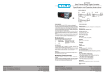
PROBES (Pro)
P0 = ºC or ºF, Temperature scale
P1 = Ambient probe calibration
Degrees shift of the ambient probe.
P2 = Defrosting probe calibration
Degrees shift of the defrosting probe.
P3 = Product probe calibration
Degrees shift of the product probe.
P4 = Decimal point
P5=Probe to be viewed normally on the display.
sd1 = ambient probe.
sd2 = defrosting probe.
sd3 = product probe
P6 = Probe 2 Defrosting present.
If there is a probe 2 conected to thermostat
P7 = Probe 3 Product present.
If there is a probe 3 conected to thermostat
Electrónica Keld, S.L.
Pol.Ind. Empresarium. C/Lentisco 15
50720 - La Cartuja Baja, ZARAGOZA
Spain
INICIALIZATION(INI)
Hor = Hour
Min = Minutes
E0 = Digital input configuration.
Off = Digital input disabled.
Al = External alarm. There is an alarm if input is short-circuited.
In = Door open if input is short-circuited.
def = Order to initiate a defrost if input is short-circuited.
ndf = No defrosting will be made if input is short-circuited.
H0 = Factory Configuration. Record Factory Configuration.
H1 = Master/Slave
H1=Master. The thermostat issues defrosting orders to slave
connected thermostats through the digital input
H1=Slave. The thermostat performs defrosting ordered by the
master connected to its digital input.
In both cases the input must be Eo=def
H2 = Keyboard protection.
Yes =Keyboard protected. To modify Set, activate/de-activate
defrosting and activate/de-activate continuous cycle we have to
enter the code and then quit. The protection is romeved
momentarily. It is activated again 1 minute after the last key is
pressed.
No = Keyboard not protected.
H3 = Delay time on connecting.
Until this time has elapsed since turning-on power, the
compressor will not start-up.
H4 = Address for serial communication.
H5 = Input code to parameters.
This code is set to 00 from factory.
H6 = Type of Probe
PTC or NTC
H7 = Configuration 2 Relay and H8 = Configuration Relay 3
We can choose that it is Light (Lih), Fan (Fan), Alarm (ALA) or
Defrosting (dEF)
H9 = Configuration Relay 4 (Single KLT43)
We can choose that it is Light (Lih), Fan (Fan), Alarm (ALA),
Defrosting (dEF) or second compressor (Con)
HdE = Hours(HdE):Minutes(MdE) the defrost will begin at
MdE = Hours(HdE):Minutes(MdE) the defrost will begin at
Phone: +34 976 429 099
Fax:+34 976 593 532
E-mail: [email protected]
Web: http://www.keld.es
ETDT1412I_090318
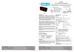
KLTX3
Temperature Controllers
ELECTRÓNICA
Specification and Operating Instructions
Wiring Diagram
KLT43
KLT13 KLT23 KLT33
1 2 3 4 5 6
sd1 sd2 sd3 gnd in
Rel1
SLINK
Defrosting (DEF)
d0 = Type of defrosting.
re = defrosting without connecting the compressor.
in = defrosting by connecting the compressor.
d1 = End of defrosting temperature.
When this temperature is reached the defrosting will end.
d2 = Maximum defrosting time.
The defrosting will stop when this time is reached.
If it is zero there will be no defrosting.
d3 = first Hour defrosting of the day
From 00:00 hours the first defrosting is at d3 hours.
Until this time no defrosting is performed
d4 = Delay first defrosting.
Time to carry out the first defrosting if d3 = yes.
d5 = Display during the defrosting.
Off = The curren temperature will be shown during defrosting.
On = The temperature at defrost beginning is frozen on display
until the end of defrosting and until the current temperature is
equal or lower than the initial one, or until d6 time elapses.
def = Label -d- is displayed during defrosting, until the end of
defrosting and until the current temperature is equal or lower than
the initial one, or until d6 time elapses.
d6 = Display return limit.
Maximum time before viewing the current temperature again
after defrosting.
d7 = Compressor drip time.
Time since defrosting ends until the compressor can be
connected.
d8 = Interval between defrosting.
Time between the start of a defrosting and the start of the
following one.
If it is zero defrosting is not done automatically by time.
d9 = Fan operation during defrosting time.
It determines if the fan is connected or not during defrosting.
d10 = Fan drip time.
Time since defrosting ends until fan can be connected.
d11 = Minimum Time duration defrosting
Once defrosting begins it stays at least during this time
d12 = Fan & defrosting control probe.
sd1 = ambient probe.
sd2 = defrosting probe
sd3 = product probe
d14 = Units to count the defrosting cyle.
rt = according to the time of working of the controller.
ct = according to the time of working of the compressor.
ALARMS(ALA)
A0 = Fan & alarm differential.
This is the temperature difference between the on and off cycle of
the alarms and fan
A1 = Maximum alarm.
High alarm ON at Set+A1. High alarm OFF at Set+A1-A0.
A2 = Minimum alarm.
Low alarm ON at Set-A2. Low alarm OFF at Set-A2+A0.
A3 = Alarm exclusion time after continuous cycle.
During the continuous cycle, and this time after it, temperature
alarms will be ignored.
A4 = Alarm exclusion time after defrosting.
During the defrosting and this time after it, temperature alarms
will be ignored.
A5 = Alarm exclusion time after opening the door.
While the door is open (if A5>0) and time A5 after closing it,
alarms will be ignored.
A6 = Alarm exclusion after connection.
Until this time has elapsed since the connection, temperature
alarms will be ignored.
A7 = Temperature alarm time validation.
Time since the alarm situation occurs, until it is given.
A8 = Probe Alarm.
sd1 = ambient probe
sd2 = defrosting probe
sd3 = product probe
SLINK
Parameter description - continuation
7 8 9
gnd
Rel4
Rel3
amb. def. pro. in.
Rel2
10 11 12 13 14 15 16 17 18 19
1 2 3 4 5
6 7 8 9 10 11
Rel2 Rel1 Com Rel3
230Vac
230Vac
Description
The KLT13I, KLT23I , KLT33I and KLT43I series are electronic
temperature controllers for cold refrigeration units.
These devices allow to control the Compresor, Defrost, Fan,
Alarm and Light, and have up to 3 probes. The KLT43I series
includes the possibility of two compressors.
NTC or PTC probes can be selected by parameter. They have
also a configurable digital input according to parameter E0
These thermostats allow the Master/Slave configuration to
synchronize the defrost between different thermostats.
Errors and alarms can be viewed on display.
HACCP option can record temperature, time of temperature
alarms and power fails.
The Slink multifunction input allows an easy programming of the
parameters with a KLKEY, the connection of a Real Time Clock
and Memoery Module or the connection of a R485 Module
Interface.
Model references
The model reference is given by: KLTX3I -DVYZ
Each sufix can take the following values:
V
Y
Color:
Supply Voltage:
Z
Temp: Units:
R:Red, G:Green, B:Blue
230:230Vac, 115:115Vac
24:24Vac/dc, 12:12Vac/dc
C:ºC, F:ºF
Installation
The thermostat must be located in a place protected from
vibrations, impacts, water and corrosive gases.
It will be made a 71x29mm panel cut-out to insert the
thermostat (apply silicone to make it leaktight ). Then the fixing
clips must be fasten, sliding it onto the thermostat, until it is well
secure. Do not force the screw tightening if the U-brackets are
used.
Technical Data
Supply voltages
115Vac+/-10%, 230Vac+/-10%
12Vac/dc +/-10%, 24Vac/dc +/-10%
Supply powers
3.6VA (230V) 1.5VA (12V)
Storage temperature
-20ºC to 80ºC (-4 to 176ºF)
Operating temperature
0ºC to 65ºC (32 to 149ºF)
Temperature probe
PTC / NTC
Probe range
PTC
NTC
Temperature accuracy
Better than 1% of full scale
Temperature resolution
0.1º PTC , 1º NTC
Displays
3-digit and sign
SLINK
-50ºC to 150ºC (-58 to 302ºF)
-50ºC to 110ºC (-58 to 230ºF)
For KLKEY or Real Time Clock and Memory Module
or Communication Module
Outputs
KLT43 Model
REL 1
REL 4
REL 2
REL 3
SPDT Relé Carga Resistiva 16A
1HP 240Vac -- 10FLA, 60LRA 240Vac
SPDT Relé Carga Resistiva 16A
1HP 240Vac -- 10FLA, 60LRA 240Vac
SPST Relé Carga Resistiva 8A 240Vac
SPDT Relé Carga Resistiva 8A 240Vac
KLT13,KLT23,KLT33 Models
Wiring
REL 1
Avoid installing the cables of the probes and the digital input, in
the proximity of any power cable. If the lenght of the probe cables
measure is longer than 100 metres, a re-calibration adjustment
must be made P1 , P2 ó P3
REL 2
REL 3
Dimensions
Maintenance
Front Protection
SPST Relé Carga Resistiva 16A
1HP 240Vac -- 10FLA, 60LRA 240Vac
SPST relay resistive load 5A 240Vac
SPST Relé Carga Resistiva 8A 240Vac
77 x 36 x 62 mm (3.03 x 1.42 x 2.44 in)
IP64
Cleaning
Clean the surface of the controller with a soft, damp cloth.
Never use abrasive detergents, petrol, alcohol or solvents.
Repairs
All the repairs must be carried out by authorised people.
Electrónica Keld, S.L.
Pol.Ind. Empresarium. C/Lentisco 15
50720 - La Cartuja Baja, ZARAGOZA
Spain
Phone: +34 976 429 099
Fax:+34 976 593 532
E-mail: [email protected]
Web: http://www.keld.es
ETDT1412I_090318
Front Operation
Set Point Setup
- Press key SET. The Set label appears.
- Press SET again. Current set point value appears blinking.
- Press UP or DOWN to increase or decrease the value.
- Press SET to confirm the new value.
- Press SET and DOWN to exit
Time pogramming
- Press key SET. The Set label appears.
- Press UP or DOWN to go to Hour or Minute
- Press SET to see the value.
- With UP and DOWN set the desired new value.
- Press SET for 8 seconds, Pro will appear on the display once the
time has been correctly programmed
-Press SET + DOWN to quit or wait for 1 minute (keyboard timeout).
Parameter programming
- The parameters are grouped in the menus COM, DEF, PRO, ALA,
INI
- Press SET for 8 seconds. Value 00 appears blinking.
- Set the code with UP and DOWN (it is set to 00 from factory).
- Press SET to confirm the code. If it is right, the label of the first
menu will appear.
- With UP and DOWN go to the desired menu.
- Press SET, the label of the first parameter of menu will appear.
- With UP and DOWN go to the desired parameter label of the list of
parameters.
- Press SET to see the value.
- With UP and DOWN set the desired new value.
- Press SET to confirm it and exit to the parameter label.
-Press SET + DOWN to go to menu list.
-Press SET + DOWN to quit programming or wait 1 minute
(keyboard timeout).
To record a standard configuration
- Access to parameter H0 as explained in Parameter programming.
- Choose desired configuration.
For series KLT13I-Dx: H0 is set to 0
For series KLT23I-Dx: H0 is set to 1
For series KLT33I-Dx: H0 is set to 2
For series KLT33I-Dx: H0 is set to 3
- Press SET for 8 seconds, and the thermostat will be reset.
-Press SET + DOWN to quit or wait for 1 minute (keyboard timeout).
Manual Defrost.
Pressing UP key for 8 seconds defrost is activated. Repeating the
operation is deactivated.
Continuous cold cycle.
Pressing DOWN key for 8 seconds a continuous cold cycle begins.
Repeating the operation the cycle finalizes.
Setting keyboard code to zero
The keyboard code can be programmed to zero by turning off the
controller, and turning it on again, while the key SET is pressed.
Alarm validation
An active alarm can be validated (the alarm output will be turned off)
pressing the SET and DOWN keys simultaneously.
Led Indications
Out:
It indicates Compresor connected. It blinks when a
continuous cold cycle has to be initiated and has to wait until the
minimum compressor stoppage time is over.
Def: It indicates defrosting is activated.
Fan: It indicates ventilator is connected.
Alarm: It indicates an error or alarm. It blinks when the alarm is validated by
the user.
Display Messages
In normal operation the probe temperature selected by P5 will be displayed.
The following messages can also appear :
- Err
Memory reading error.
- ErP1, ErP2, ErP3
Probe1 , 2 or 3 error
- Eri Internal parameter error. In this case, enter the standard configuration,
as it is indicated in “To record a standard configuration”.
-
ALH High temperature alarm.
ALL Low temperature alarm.
ALE External alarm.
AEH High temperature and external alarm.
AEL Low temperature and external alarm.
ooo Open probe.
--Short-circuited probe.
DON Defrosting activated.
DOF Defrosting de-activated or cannot be done.
CON Continuous cold cycle activated.
COF Continuous cold cycle de-activated or cannot be done.
-dThermostat on defrosting.
To view the probe not chosen by P5, press SET+UP
The display blinks when there is an error recording a parameter in memory or
when awaiting confirmation of a value.
Operation in Error Case
If the ambient probe fails, the thermostat will connect the compressor
according to parameters c2 and c3, being able to perform defrosting and
continuous cold cycles.
If the memory fails the thermostat will connect the compressor ON for 5
minutes and OFF for 5 minutes, not being able to perform defrosting or
continuous cold cycles.
Two Compressors Operation
In this case, when the thermostat demands cold (Sd1 >= Set+r0) the first
compressor to be connected is the compressor with less running hours, and
after c6 seconds, the second compressor is also connected. When the
thermostat begins to cool, and Sd1<Set+r0/2 is reached, the second
compressor stops, and the first one continues. The second will be stopped
when Sd1<Set. Nevertheless, if before stopping the first compressor, Sd1 >=
Set+r0, the second compressor starts running again.
HACCP
If this option is activated, the thermostat registers up to 5 alarms of the types
Hight, Low, and blackout. These alarms can be seen in the menu Registry of
Alarms (HAC). To acced to this menu, proceed as for the parameters menu.
The first value that appears is the number of registered alarms. Afterwards,
for each alarm (if it has existed), the value of the temperature and the time of
the alarm. For the disconnection alarm, the temperature when returning the
connection is registered, as well as the time until the correct values are
reached. (Probe<Set+A1-A0)
When the elapsed time is showed it will appear xxd (days).Pressing UP xxH
(Hours) will be shown, and pressing UP again, xxn (Minutes) will be
displayed. When located over a temperature of alarm or time, pressing
UP+DOWN during 2 seconds, both recorded data of the alarm (time and
temperature value) are deleted.
In the Ald menu, and pressing UP+DOWN keys during 2 seconds, all the
recorded data of alarms are deleted.
SLINK
ON OFF Thermostat
In this input we can connect a programming key to read or to write the
parameters. We can also connect a clock module so that the hour of
the thermostat goes with a realtime clock. If we manage the system
with a PC we can connect it to the thermostat through this input with a
communication module.
Pressing the keys SET+DOWN for 8 seconds the thermostat will
turn-on or turn-off
List of parameters
ON OFF Light
If we have a relay setup as light, pressing keys UP+DOWN for 3
seconds the thermostat will turn-on or turn-off the light
Con Description
Units
Range
Set
r0
r1
r2
r6
F0
F1
c0
Degrees
Degrees
Degrees
Degrees
Range
Degrees
Option
Minutes
r1 to r2
0,1 to 20
-99,9 to r2
r1 to 302
off /on /con
-99.9 to 302
no/yes
0 to 240
3.0
1.0
-50.0
150
con
28.0
yes
1
Defrosting Cycles
h-m
Minutes
Minutes
Minutes
0.0 to 18
0 to 999
0 to 999
0 to 240
1.0
5
5
0
Hour/Minutes Parameters H-M
Minutes
0 to 240
1
Minutes
0 to 240
30
dEF Description
Units
Range
Factory
d0
d1
Range
Degrees
re /in
-99.9 to 302
re
80.0
Minutes
h-m
Minutes
Range
Minutes
Minutes
h-m
Range
Minutes
Minutes
Range
Option
0 to 240
00,0 to 18,0
0 to 999
off/on/-d0 to 240
0 to 240
00,0 to 18,0
no/yes
0 to 240
0 to 240
sd1/sd2/sd3
rt / ct
30
00.0
0
c1
c2
c3
c4
c5
c6
d2
d3
d4
d5
d6
d7
d8
d9
d10
d11
d12
d14
Set point
Differential or hysteresis
Minimum value for set point
Maximum value for set point
Fan operation
Fan stoppage temperature
Fan works with door open
Minimum compressor stoppage
time
Continous cycle time
ON time of fault cycle
OFF time of fault cycle
Minimum ON time
of the compressor
Minimum time between two
connections of the compressor
Delay time for second compresor
Type of defrosting
Temperature at which defrosting
will stop
Maximum defrosting time
First Hour of Day for Defrosting
Delay of first defrosting
Display on defrosting
Display return limit.
Compressor drip time.
Interval between defrostings.
Fan works on defrosting.
Fan drip time
Minimun Defrosting time
Fan/defrosting control probe
Units to count the defrosting
Cycle
Pro Description
Units
P0
P1
P2
P3
P4
P5
P6
P7
Option
Degrees
Degrees
Degrees
Option
Range
Option
Option
Temperature scale
Ambient probe 1 calibration
Defrosting probe 2 calibration
Product probe 3 calibration
Decimal point
Probe to display
Probe 2 present
Probe 3 present
Range
ºC/ºF
-20,0 to 20,0
-20,0 to 20,0
-20,0 to 20,0
no/yes
sd1/sd2/sd3
no/yes
no/yes
Range
Factory
15
0
8.0
no
0
0
sd2
rt
ºC
0.0
0.0
0.0
no
sd1
yes
no
Units
A0
A1
A2
A3
Factory
Degrees
Degrees
Degrees
h-m
0.1 to 20.0
0.1 to 99.9
0.1 to 99.9
0.0 to 18.0
4.0
8.0
8.0
1.1
h-m
0.0 to 18.0
1.1
h-m
0.0 to 18.0
1.1
Fan and alarm differential
Maximum alarm temperature (1)
Minimum alarm temperature (1)
Time without alarm
after continous cycle
Time without alarm after
defrosting
Time without alarm after
opening the door
Time without alarm
after connection
Alarm verification time
Probe for alarm
h-m
0.0 to 18.0
1.1
h-m
Range
0.0 to 18.0
sd1/sd2/sd3
1.1
sd1
Ini
Description
Units
Hor
Min
E0
H0
H1
H2
H3
H4
H5
H6
H7
H8
H9
H10
HdE
MdE
Hour
Hours
0..23 0
Minutes
Minutes
00..59
0
Configure digital input
Range
off/Al/In/def
def
Factory Settings
Range
0 to 3
Master/Slave
Range
Mst/Slv
MSt
Keypad protection
Option
no/yes
no
Delay time on connecting
Seconds
0 to 240
0
Address for serial communication Numeric
0 to 999
0
Keyboard code
Numeric
0 to 999
0
Type of probe
Option
ptc / ntc
ptc
Relay 2 Setup
Option
Lit/FAn/ALA/dEF
dEF
Relay 3 Setup
Option
Lit/FAn/ALA/dEF
dEF
Relay 4 Setup
Option Lit/FAn/ALA/dEF/Con Con
HACCP Activated
Option
no/yes
no
Next defrost Time
Hours
(only read)
Next defrost Time
Minutes
(only read)
A5
A6
A7
A8
Range
It is a way to show hours and minutes in 3 digits
The two first digits are the hours and the third the tens of minutes.
E.g.
2.4
2 hours 40 minutes
8.0
8 hours 0 minutes
10.3 10 hours 30 minutes
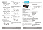
Parameter description
COMPRESSOR (CON)
SET = Work set point.
Temperature we wish to maintain the machine. Variable between r1
and r2.
r0 = Differential.
When ambient probe temperature >= Set+r0 Compresor ON
When ambient probe temperature <= Set Compresor OFF
r6 = Fan operation on regulation.
Off = Fan does not connect on regulation.
On = Fan is always connected on regulation.
Con= Fan linked to compressor start-up.
(Fan ON if allowed by the temperature given by F0)
Factory
ALA Description
A4
The cycles of defrosting can be performed counting total time (d14=
rt) or counting the time only when the compressor is connected
(d14= ct).
First defrosting will be always made at the hour d3
And the others with the cycle given by d8.
Factory
F0 = Fan temperature limit.
Fan OFF on regulation when probe temperature setup in d12
is >= F0.
Fan ON on regulation, when temperature is =< F0-A0.
The operation of the fan on regulation is determined also by r6.
F1 = Fan stop if door opened.
No = The fan does not stop on regulation and continuous cycle
when opening the door.
Yes = The fan stops on regulation and continuous cycle when
opening the door.
c0 = Minimum compressor stop time
Minimum time since compressor stops until it is starts again.
c1 = Continuous cycle time.
Duration of a continuous cold cycle.
c2 = ON time of fault cycle, when ambient probe is broken
c3 = OFF time of fault cycle, when ambient probe is broken
c4 = Minimum time of working of the compressor
Minimum time since compressor starts until it stops.
c5 = Minimum time between two connections of the compressor
Minimum time since compressor starts until it starts again.
c6 = Delay Time 2 Compressor
Time since compressor 1 is connected until compressor 2 is
connected, if it is necessary to connect it and if H7=Com