1
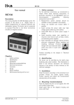
Newall Measurement Systems TM Magnasyn Linear Encoder INSTALLATION MANUAL CONTENTS Page 1.0 MECHANICAL PROPERTIES 1 1.1 Tape Composition 1 1.2 Backing bar 1 1.3 Chemical Effects of Magnetic Tape and Adhesive 2 1.4 Surface Preparation 2 1.5 Adhesion Temperature 2 2.0 INSTALLATION 3 2.1 Head Alignment Tolerances 3 2.2 Head Installation 4 2.3 Tape Only Installations 5 2.4 Backing Bar Installations 2.3.1 2.3.2 2.3.3 2.4.1 2.4.2 2.4.3 Cover Strip End Fixing Options Rotary (non-linear) Installations Standard Mounting Options Calculation of Number of Backing Bar Brackets Required Long Scales 5 6 7 8 8 8 9 Technical Specification Construction: Aluminum Housing 6mm (¼” ) Fully interlocked Stainless Steel conduit armoured cable. 9-way ‘D-Type’ connector or Flying lead Dimensions (reader head): Height Width Length Weight 26mm 24mm 70mm 0.640Kg Operating Voltage: 5 VDC ± 4% ripple < 50mV Supply Voltage Fluctuation: Within operating voltage range Maximum Power Consumption: (1.023”) (0.787”) (1.693”) (1.410lbs) (plus cable ferrule) (max. inc. 3.5m cable) <200mA Operating Temperature: 0 to 60oC (32 to 140oF) Storage Temperature: -20 to 70oC (-4 to 158oF) Outputs: Differential Quadrature with Synchronised Reference mark Via. RS422 compatible TTL line drivers Output frequency: 100kHz max (per channel) Proportional to speed Maximum Speed: 4m/s Maximum cable length: 22m (using Newall standard cables + extensions) Environmental Conditions: IP67 EMC Compliance: BS EN 50081-2 Electromagnetic Compatibility Generic Emission Standard – Industrial Environment (157”/s) BS EN 50082-2 Electromagnetic Compatibility Generic Immunity Standard – Industrial Environment NOTE: NEWALL MEASUREMENT SYSTEMS LIMITED RESERVES THE RIGHT TO CHANGE THE SPECIFICATION WITHOUT NOTICE 1.0 MECHANICAL PROPERTIES 1.1 Tape Composition The magnetic tape comprises three components when installed as Tape only, Figure 1.1. A B C Sensor side 1.8mm (0.07”) Lengths to 32m 10mm (0.394”) Figure 1.1 Laminated tape construction A Non ferrous band used to mechanically protect the rubber cover 0.2mm (0.008”) thick. For flexibility in transport this is supplied separately from the tape assembly and is mounted, on site, using supplied double-sided adhesive tape. B The highly flexible rubber tape contains the magnetised poles used by the encoder to determine incremental movements. C Ferrous flexible band pre-assembled to the magnetic tape. This medium holds the tape stable and provides the required magnetic path between poles. This is attached to the machine substrate or the backing bar carrier by means of double-sided adhesive tape. 1.2 Backing Bar A B C 30mm (1.18”) D Figure 1.2 Backing bar assembly construction A Non ferrous band 0.2mm (0.008”) thick used to mechanically protect the rubber cover. For flexibility in transport this is supplied separately from the tape assembly and is mounted, on site, using supplied double-sided adhesive tape. B Aluminum backing bar extrusion 6.35mm (0.25”) thick. C Magnatised rubber ‘Encoder’ tape. Mounted in to backing bar channel using double-sided adhesive tape. D Optional reference marker tape containing a single magnetic pole. Located in parallel channel to the encoder tape. Note: When Indexing always approach the index marker from the same direction. Page - 1 - 1.3 Chemical Effects of Magnetic Tape and Adhesive Chemicals which have no effect: Formic Acid Cottonseed Oil Formaldehyde 40% Glycerine 93o N-Hexan Isooktan Linseed Oil Sour Milk Mineral Oil Soyabean Oil Vinegar 30% Isopropalene Kerosene Oil Acid Sea Water Stearin Acid Chemicals which have a detrimental effect: Acetone Acetylene Ammonia (neat) Benzene Steam Acetic Acid 20% Chemicals which are harmful: Benzol Paint Thinners Nitro Benzol Saltoetre Solution Salt Solution 37% 93oC (200oF) Salt Acids 37% 93oC (200oF) Turpentine Carbon Tetrachloride Toluol Tricoethylene Tetrahydrofuran Xylol 1.4 Surface Preparation The laminated tape must be mounted, using the double-sided tape provided, to a clean, dry and flat surface. Isopropanol wipes are provided for this purpose. Ensure the surface has time to dry after cleaning. On materials such as copper, brass, etc, ensure that the surface is clear of any oxidant patina (corrosion). 1.5 Adhesion Temperature For best adhesion results, installation should occur within a temperature range of +21 to +38oC (70 to 100oF). Once correctly applied the integrity of the bond is maintained even when exposed to temperatures below 0oC (32oF). The bond will reach maximum strength within 72 hours at 21oC (70oF). Note: If the surface temperature of the substrate is 11oC (52oF) or less, the adhesive will be too hard and will result in poor bonding. Page - 2 - 2.0 INSTALLATION The Magnasyn Digital tape is to be mounted at least 500mm (20”) away from sources of inductive and capacitive interference such as; circuit breakers, relays, motor contacts, PWM regulators, etc. Locate the head cable so that it is run separately from power cables in order to reduce the likelihood of noise pickup. The cable consists of a 6mm (¼”) conduit armour containing a PU coated multicable twisted pair core. The Magnasyn Digital can be installed using one of the following methods; Tape only With Backing bar (Rotary applications must be of this form) 2.1 Head Alignment Tolerances The maximum installation alignment tolerances can be seen in Figure 2.1. ± 3mm (0.12”) Offset < ± 5o Roll Ride Height ± 0.8mm (0.03”) max. < ± 5o < ± 1.5o ® Yaw Pitch SEAL EDDO NOT O PEN Figure 2.1. Reader head alignment tolerances A plastic set-up shim is included with every reader head in order to ensure the nominally correct ride height of 0.4mm (0.01575”) is configured. This set-up shim should only be used during installation and removed before operation. Summary Alignment Offset Ride Height Roll Pitch Yaw Min. -3mm (0.12”) 0 -5o -5o -1.5o Page - 3 - Max. +3mm (0.12”) 0.8mm (0.03”) +5o +5o +1.5o 2.2 Head Installation The head bracket mounting kit contains two parts as shown in Figure 2.2. These can be configured to give the two mounting options shown in Figures 2.3a and 2.3b below. The location of the index and incremental pickup sensors can be seen in Figure 2.4. 50.80mm (2”) 50.80mm (2”) 6.35mm (0.25”) 17mm (0.67”) A A 21.5mm (0.85”) 21.5mm (0.85”) 17mm (0.67”) A A B B 10mm (0.39”) A 25.4mm (1.0”) A 18.5 ± 0.10 mm (0.73 ± 0.004”) B 38.1mm (1.5”) 10mm (0.39”) B 6.35mm (0.25”) 17mm (0.67”) 3.0mm (0.12”) 17mm (0.67”) A – 2 off Holes M4 x 12 B – 2 off Slots φ4.5 x 10 A – 4 off Holes M3 B – 2 off Slots φ4.5 x 10 Figure 2.2. Reader head bracket parts M4x12 Cap Screw 4 off Magnasyn Head Angle Plate Magnasyn Mounting Plate M3x30 Cap Cover Clip Drive-screw Magnasyn Tape Backing Bar (a) Backing Bar Bracket (b) Figure 2.3. Reader head bracket configurations Index sensor (single shot) Incremental (Tape) sensor Figure 2.4. Location of sensors Page - 4 - 2.3 Tape Only Installations For both linear and rotary installations ensure surface is even and well prepared as described in Section 1.4. If the surface can not be cleaned or is irregular then a backing bar installation is required (Linear measuring only). See Section 2.5. Measure the overall length of machine travel and ensure that the supplied length of tape is correct. If the tape is oversize then trim back preferably using a guillotine. Mark the line of the tape on the machine bed using a pencil or marker pen. Starting at one end of the installation, start to peel back the tape adhesive cover paper approximately 15cm (6”). Aligning the end of the tape to the guide marks applied to the machine bed press the Magnasyn tape down firmly. Working along the length of travel continue to peel back the adhesive paper cover ensuring that the Magnasyn tape is being firmly pressed down in to the mounting surface. At all times, check that the Magnasyn tape is following the guidelines previously marked on the machine bed. Once the tape has been located on the machine, using a dry, clean, lint-free cloth, firmly rub the tape along the line of travel. This will ensure that any air pockets are removed and that the adhesive is in firm contact with the machine mounting substrate. 2.3.1 Cover Strip Once the tape has been applied to the mounting surface, a protective 0.2mm (0.00787”) stainless steel cover strip is to be applied. This protects the soft magnetised rubber encoder tape from environmental conditions. Apply the cover strip in the same manner as the Magnasyn tape. Starting from one end, peel back the adhesive cover paper and align the cover strip with the Magnasyn tape. Work along the length of travel peeling back the adhesive cover paper and firmly pressing down on the cover strip. Once the cover strip has been located on the machine, using a dry, clean, lint-free cloth, firmly rub the tape along the line of travel. This will ensure that any air pockets are removed. Page - 5 - 2.3.2 End Fixing Options 1. Adhesive tape only 2. Screw fixing 3. Newall end clamp (recommended) Figure 2.5 Optional end tape fixtures Option 1) Does NOT secure the tape ends to the mounting surface. However, it does provide a mechanism whereby the reader head can traverse past the end of the scale. This method can result in the scale peeling from the mounting surface if exposed to coolants or cutting fluids. If this fixing method is to be adopted, a two-part epoxy resin should be used to bond the scale to the mounting surface and the cover to the scale for the last 25mm (1”). Option 2) Requires that the scale is mounted, the cover then centre-punched and the scale then drilled. The machine surface should then be tapped to accept a fixing bolt. Newall does not supply parts for this fixing method. This method offers a very secure fixing, however 25mm (1”) of over travel should be allowed at each end to accommodate the fixing bolt. Option 3) This method consists of bonding the scale to the mounting surface and encapsulating it in a scale end cover and as such removes the need for any additional drilling. A two-part epoxy resin is employed for this purpose along with a moulded scale end cover. An optional fixing kit containing all the parts required for this method of mounting is available. 25mm (1”) of over travel should be allowed at each end to accommodate the mounting of the end clamp. Page - 6 - 2.4 Rotary (non-linear) Installations ROTARY INSTALLATIONS CAN NOT USE BACKING BAR Rotary installations are essentially “Tape only” installations as described in Section 2.3. If the machine or device is likely to move through a complete revolution then a special form of tape end fixing is required as indicated in Figures 2.6 and 2.7. If this is not the case, then the installation can be treated as a simple tape installation as described in Section 2.3. It should be noted that Magnasyn CAN NOT provide 360o of measurement. Where the tape is joined signal integrity WILL be lost and the counter will need to be re-datumed. Errors are NOT repeatable across a join. 50mm (2”) Figure 2.6 Layered tape end fixing Forming an overlap at each layer in order to provide structural integrity forms the join. The layers are bonded to each other and the machine substrate using a two-part epoxy resin (available in the scale end clamp fixing kit). Pressure is to be applied to the join until the adhesive has set. This is achieved by trimming the ends of the tape: Cover Remove 50mm (2”) of Flexible metal band Remove 50mm (2”) of Inductive rubber tape Figure 2.7 Formation of the overlap ‘layered’ join The rubber tape should be cut cleanly across the width of the tape with a sharp knife or scalpel. The flexible metal band and cover strip is to be cut with a guillotine, tin snips or similar. All burrs are to be removed. Page - 7 - 2.5 Backing Bar Installations Backing bar is to be implemented where the mounting surface is uneven or not continuous. Uneven surface Mounted on stand-offs Figure 2.8. Typical backing bar installations 2.5.1 Standard Mounting Options 16mm ± 1mm (0.63” ± 0.04”) Backing bar centre line 3mm (0.12”) max Figure 2.9. Backing bar mounting bracket installations Backing assemblies are supplied as kits to be assembled directly on to the machine surface. The tape is applied after the mounting of the backing bar has been completed. 2.5.2 Calculation of Number of Backing Bar Brackets Required It is recommended that backing bar mounting brackets are to be mounted evenly spaced 500mm (20”) apart where possible. No. Brackets = (Overall Length (m) x 2) + 1 i.e. for a 2m length 5 brackets are required. NO SINGLE UNSUPPORTED LENGTH OF BACKING BAR SHOULD EXCEED 600MM (24”) Page - 8 - 2.5.3 Long Scales Where long travels are required, (up to a maximum of 32m, 1260feet), backing bar sections are to be joined together during installation to form a continuous length. Each join must occur at a point where a bracket can be mounted to ensure the sections are locked to each other and to the machine surface. NO JOIN IS TO BE LOCATED WHERE IT CAN NOT BE SUPPORTED. 9 Good Join Bad Join 8 Figure 2.10. Backing bar joining positions It is imperative when backing bar is to be used that machines are correctly surveyed in order to ensure correct installation. 15mm ± 1 mm (0.59” ± 0.04”) Backing bar joint line Figure 2.11. Location of the backing bar joint on a support bracket Where required, due to mounting limitations, additional mounting brackets can be ordered. Page - 9 - NEWALL MEASUREMENT SYSTEMS LTD Technology Gateway, Cornwall Road South Wigston, Leicester, LE18 4XH United Kingdom E-mail: [email protected] NEWALL ELECTRONICS INC 1778 Dividend Drive . Columbus . Ohio . 43228. USA Tel: (+1) 614 771 0213 . Fax: (+1) 614 771 0219 E-mail: [email protected] Website: www.newall.com Issue Date: February 2001