1
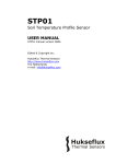
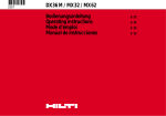
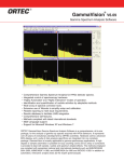
TMX32 User's Manual
®
Real Time Devices, Inc.
“Accessing the Analog World”®
Publication No. TMX32-9630
TMX32
User's Manual
®
REAL TIME DEVICES, INC.
Post Office Box 906
State College, Pennsylvania 16804
Phone: (814) 234-8087
FAX: (814) 234-5218
Published by
Real Time Devices, Inc.
P.O. Box 906
State College, PA 16804
Copyright © 1996 by Real Time Devices, Inc.
All rights reserved
Printed in U.S.A.
9630
Table of Contents
INTRODUCTION .................................................................................................................................... i-1
Multiplexing ........................................................................................................................................................... i-3
Thermocouple Compensation ................................................................................................................................. i-3
MX32 Compatibility ............................................................................................................................................... i-3
What Comes With Your Board .............................................................................................................................. i-3
Using This Manual ................................................................................................................................................. i-4
When You Need Help ............................................................................................................................................. i-4
CHAPTER 1 — BOARD SETTINGS ................................................................................................. 1-1
Factory-Configured Switch and Jumper Settings ................................................................................................. 1-3
P3 and P4 — A/D Converter Board Channel Select (Factory Setting: Channel 1/GND) ............................... 1-4
P5 — Gain Select (Factory Setting: G0 and G1 Installed (Gain = 1)) ............................................................ 1-6
P6 — Temperature Sensor Voltage Output Select (Factory Setting: Disabled) .............................................. 1-6
P7 — Offset Adjustment Source Select (Factory Setting: G (TMX32 TR1 Offset Adjust)) .......................... 1-7
P8 — Power Source Select (Factory Setting: Internal) .................................................................................... 1-7
P9 — Single-Ended/Differential Analog Inputs (Factory Setting: Single-Ended) .......................................... 1-7
CHAPTER 2 — BOARD CONNECTIONS ........................................................................................ 2-1
Connecting to the A/D Converter Board ............................................................................................................... 2-3
Connecting to a 50-pin A/D Converter Board .................................................................................................. 2-3
Connecting to the Signal Sources ......................................................................................................................... 2-4
Connecting Single-Ended Analog Inputs ......................................................................................................... 2-4
Connecting Differential Analog Inputs ............................................................................................................ 2-5
CHAPTER 3 — BOARD OPERATION ............................................................................................. 3-1
Multiplexing Circuitry ........................................................................................................................................... 3-3
Input Voltage Range .......................................................................................................................................... 3-3
Gain .................................................................................................................................................................... 3-3
Offset Voltage Adjustment ............................................................................................................................... 3-4
Digital Control Lines ......................................................................................................................................... 3-4
Temperature Sensing Circuity for Thermocouple Cold Junction Compensation ................................................ 3-5
Reducing the Noise on Your Analog Inputs ......................................................................................................... 3-8
Input Signal Conditioning ................................................................................................................................. 3-8
Low-Pass Filter, Single-Ended Inputs ......................................................................................................... 3-8
Low-Pass Filter, Differential Inputs ............................................................................................................ 3-9
Attenuator, Single-Ended Inputs ................................................................................................................ 3-10
Current Shunt, Differential Inputs .............................................................................................................. 3-10
Grounding the Negative Input, Differential Inputs .................................................................................... 3-10
Other Noise Reduction Techniques ................................................................................................................ 3-10
APPENDIX A — TMX32 SPECIFICATIONS ................................................................................... A-1
APPENDIX B — TMX32 50-PIN I/O CONNECTOR PINOUT ...................................................... B-1
APPENDIX C — MX32 CONFIGURATION ..................................................................................... C-1
APPENDIX D — WARRANTY ........................................................................................................... D-1
i
ii
List of Illustrations
1-1
1-2
1-3
1-4
1-5
1-6
1-7
1-8
1-9
2-1
2-2
2-3
2-4
2-5
3-1
3-2
3-3
3-4
3-5
3-6
Board Layout Showing Factory-Configured Settings ............................................................................. 1-3
Channel Select Jumpers, 8-Channel A/D Boards .................................................................................... 1-4
Connecting Channel 1 to a 16-Channel A/D Board ................................................................................ 1-5
Connecting Channel 9 to a 16-Channel A/D Board ................................................................................ 1-5
Gain Select Jumpers, P5 .......................................................................................................................... 1-6
Temperature Sensor Voltage Output Select Jumpers, P6 ....................................................................... 1-6
Offset Adjustment Source Select Jumper, P7 ......................................................................................... 1-7
Power Source Select Jumper, P8 ............................................................................................................. 1-7
Single-Ended/Differential Jumper, P9 ..................................................................................................... 1-7
P1 I/O Connector Pin Assignments ......................................................................................................... 2-3
Board Layout, TB1, TB2, and TB3 ......................................................................................................... 2-4
Single-Ended Input Connections ............................................................................................................. 2-5
Differential Input Connections Without Ground Reference ................................................................... 2-6
Differential Input Connections With Ground Reference ........................................................................ 2-7
TMX32 Block Diagram ........................................................................................................................... 3-3
Single-Ended Low-Pass Filtering ............................................................................................................ 3-9
Differential Low-Pass Filtering ............................................................................................................... 3-9
Single-Ended Attenuator ........................................................................................................................ 3-10
Differential Current Shunt ..................................................................................................................... 3-11
Differential IN- Grounding .................................................................................................................... 3-11
iii
iv
INTRODUCTION
i-1
i-2
The TMX32 analog input expansion board with thermocouple compensation economically expands the input
capability of any channel on your A/D converter board to 32 single-ended or 16 differential channels. The TMX32 is
especially well suited for applications where a thermocouple sensor is monitored with other sensor types. When you
have several thermocouples, we recommended that you use the TS16 temperature sensor and input expansion board
for the thermocouple measurements.
The TMX32 external interface board features:
•
•
•
•
•
•
•
•
•
•
32 single-ended or 16 differential analog input channels,
100 kHz throughput,
On-board temperature sensor cold junction compensation for thermocouples through software,
Shunt terminals for current measurement,
Jumper-selectable gains of 1, 10, 100 or 1000 (1, 2, 4 & 8 optional), or software programmable gain,
Circuit pads to install resistors and capacitors for input signal conditioning,
±35V overvoltage protection, ±10V common mode input voltage,
Connector for external +12 volt power,
Miniature screw terminal blocks for easy input signal connection,
Extra I/O connector for daisy chaining (cascade up to 16 boards).
The following paragraphs briefly describe the major function of the board. A more detailed discussion of the
board is included in Chapter 3, Board Operation. The board setup is described in Chapter 1, Board Settings.
Multiplexing
Two on-board multiplexers receive up to 32 single-ended or 16 differential analog input channels and route
them to the selected channel on the A/D converter board. The A/D converter channel to which these inputs are fed is
selected using jumpers on the TMX32. Channel selection is made using five digital control lines connected from the
A/D converter board to the TMX32. The input voltage range of the TMX32 channels is the same as the range of
A/D converter board. Jumper-selectable gains of 1, 10, 100, and 1000 are available on the TMX32, or the gain can
be programmed through software using two digital control lines connected from the A/D board. The gains available
on the TMX32, when coupled with the gains on the A/D board, yield a very flexible signal amplification capability.
On-board circuit pads are provided so that you can construct several different types of conditioning circuitry on
each input signal.
Thermocouple Compensation
The TMX32 has an on-board sensor for cold junction temperature sensing and amplification which makes the
board ideal for thermocouple measurement. The temperature sensor’s voltage output can be routed through channel
8 or 16 on the A/D board where it is available to correct thermocouple measurements through software. This manual
provides information and general formulas for thermocouple measurement and compensation.
MX32 Compatibility
The TMX32 also replaces the earlier MX32 analog input expansion board. For those ordering an MX32,
Appendix C explains the changes made to configure the board as an MX32 equivalent.
What Comes With Your Board
You receive the following items in your TMX32 package:
• TMX32 analog input expansion board
• User’s manual
If any item is missing or damaged, please call Real Time Devices’ Customer Service Department at
(814) 234-8087. If you require service outside the U.S., contact your local distributor.
i-3
In addition to the items included in your TMX32 package, Real Time Devices offers a full line of board
accessories. Key accessories for the TMX32 include the XT50 twisted pair cable, TB50 terminal board and XB50
prototype/terminal board which can be connected to the daisy chain connector for prototype development and
easy signal access.
Using This Manual
This manual is intended to help you get your new board running quickly, while also providing enough detail
about the board and its functions so that you can enjoy maximum use of its features even in the most complex
applications. We assume that you already have an understanding of data acquisition principles and that you can
provide the software necessary to control the TMX32 board.
When You Need Help
This manual provides enough information to properly use your board’s features. If you have any problems
installing or using this board, contact our Technical Support Department, (814) 234-8087, during regular business
hours, eastern standard time or eastern daylight time, or send a FAX requesting assistance to (814) 234-5218. When
sending a FAX request, please include your company’s name and address, your name, your telephone number, and a
brief description of the problem.
i-4
CHAPTER 1
BOARD SETTINGS
The TMX32 has jumper and switch settings you can change if
necessary for your application. The factory settings are listed in the
table and shown on the board layout in the beginning of this
chapter. Should you need to change these settings, use these easyto-follow instructions.
1-1
1-2
Factory-Configured Switch and Jumper Settings
Table 1-1 (on the next page) lists the factory settings of the user-configurable switch and jumpers on the
TMX32 board. Figure 1-1 shows the board layout and the locations of the factory-set jumpers. The following
paragraphs explain how to change the factory settings.
Fig. 1-1 — Board Layout Showing Factory-Configured Settings
1-3
Table 1-1 Factory Settings
Jumper/
Switch
Function Controlled
Factory Setting
P3, P4
Select the channel that the TMX32 is connected to on the A/D converter
board. One or two jumpers must be installed, as explained later in this
chapter.
P3 = Channel 1;
P4 = Channel 1 GND
P5
Sets the TMX32 board gain (this gain is multiplied by the gain setting of
the A/D converter board to determine the overall channel gain)
Jumpers installed on G0
and G1 (gain = 1)
P6
Feeds the temperature sensor's voltage output into channel 8 or 16 on the Jumpers installed on
A/D board to enable cold junction compensation through software
DIS (disabled)
P7
Selects the TMX32 amplifier offset adjustment source
G
P8
Connects the TMX32 power to the internal power (supplied from A/D
board) or external power (supplied by user)
Connected to internal
power
P9
Sets the analog input signal type for S (single-ended) or D (differential)
Single-ended
P3 and P4 — A/D Converter Board Channel Select (Factory Setting: Channel 1/GND)
The TMX32 expands a single channel on your A/D converter board to either 32 single-ended or 16 differential
analog input channels. P3 and P4 are used to select which analog input channel on your A/D converter board you
connect to the TMX32. These connectors accommodate A/D converter boards with up to 16 channels.
For 1-8 Input Channels (single-ended or differential on A/D board): When you connect the TMX32 to an
A/D converter board with eight or fewer analog input channels, P3 is used to set the desired input channel, and P4 is
used to set the corresponding ground for that channel. For example, if you place the jumper across the pins for
channel 1 on P3 as shown in Figure 1-2, you should place the P4 jumper across the channel 1 ground pins (labeled
“9 (1)” on the board), as shown. You must install both jumpers — the selected channel jumper and the corresponding ground jumper — regardless of whether you are operating in the single-ended or differential mode.
P3
CHANNEL
SELECT
GND
SEL
P4
8
16
(8)
7
15
(7)
6
14
(6)
5
13
(5)
4
12
(4)
3
11
(3)
2
10
(2)
1
9
(1)
Fig. 1-2 — Channel Select Jumpers, 8-Channel A/D Boards
For 16 Input Channels (single-ended on A/D board): When you connect the TMX32 to an A/D converter
board with 16 input channels, only one jumper is installed on P3 and P4. Figure 1-3 shows you how to configure the
TMX32 for channel 1, and Figure 1-4 shows you how to configure the TMX32 for channel 9 when used with a
16-channel A/D converter board. Note that the leftmost row of pins on P3 carries the analog input signal for chan-
1-4
P3
CHANNEL
SELECT
P4
GND
SEL
8
16
(8)
7
15
(7)
6
14
(6)
5
13
(5)
4
12
(4)
3
11
(3)
2
10
(2)
1
9
(1)
Fig. 1-3 — Connecting Channel 1 to a 16-Channel A/D Board
P3
CHANNEL
SELECT
GND
SEL
P4
8
16
(8)
7
15
(7)
6
14
(6)
5
13
(5)
4
12
(4)
3
11
(3)
2
10
(2)
1
9
(1)
Fig. 1-4 — Connecting Channel 9 to a 16-Channel A/D Board
nels 1 through 8, the rightmost row of pins on P3 provides the common signal for all 16 channels, and the leftmost
row of pins on P4 carries the analog input signal for channels 9 through 16. The rightmost row of pins on P4 is
connected to ground and is not used when connecting to a 16-channel A/D converter board.
1-5
P5 — Gain Select (Factory Setting: G0 and G1 Installed (Gain = 1))
P5, shown in Figure 1-5, lets you select one of four gain settings: 1, 10, 100, or 1000, or set the gain through
software. The two pins, G0 and G1, are used to set the gain for all TMX32 channels to one of the four values
above. The table below shows you how to install the jumpers to achieve the desired gain (ON = jumper installed;
OFF = jumper removed).
P5
G1 G0
SPG
Fig. 1-5 — Gain Select Jumpers, P5
Gain
G0
G1
D5
D6
x1
ON
ON
0
0
x10
OFF
ON
1
0
x100
ON
OFF
0
1
x1000
OFF
OFF
1
1
The two pins, labeled SPG, are used to allow control of the gain setting through software. For software
programmable gain, install the jumpers across both pairs of SPG pins. When the jumpers are installed across these
pins, bits 5 and 6 of the digital control word written to the TMX32 from the A/D converter board are used to
program the gain.
Note that the gain set on the TMX32 board is multiplied by the gain setting of your A/D converter board to
determine the overall channel gain.
P6 — Temperature Sensor Voltage Output Select (Factory Setting: Disabled)
P6, shown in Figure 1-6, lets you select to which channel on the A/D board the temperature sensor’s voltage
is routed. When both jumpers are installed across the left pins as shown in Figure 1-6a, the temperature sensor’s
voltage is fed nowhere (disabled). When a jumper is installed across pins 8 and T, as shown in Figure 1-6b, the
voltage is fed into channel 8 on the A/D board. When a jumper is installed across pins T and 16, as shown in
Figure 1-6c, the voltage is fed into channel 16 on the A/D board. When the A/D board is being operated in the
DIFFERENTIAL mode, then two jumpers must be installed: one across 8 and T, and one across 16 and G.
Chapter 3 provides more information about the temperature sensing circuit.
P6
P6
P6
P6
8
8
8
8
T
T
T
T
16
16
16
16
G
G
G
G
DIS
Fig. 1-6a: Disabled
(Factory Setting)
Fig. 1-6b: Temperature
Sensor to Channel 8 A/D
Fig. 1-6c: Temperature
Sensor to Channel 16 A/D
Fig. 1-6a: Temperature
Sensor to Channel 8 A/D,
A/D DIFFERENTIAL Mode
Fig. 1-6 — Temperature Sensor Voltage Output Select Jumpers, P6
1-6
P7 — Offset Adjustment Source Select (Factory Setting: G (TMX32 TR1 Offset Adjust))
P7, shown in Figure 1-7, lets you select the offset adjustment source for the TMX32 amplifier. When the
jumper is placed across the pins labeled G, the offset is controlled only by trim pots on the TMX32 board. When
the jumper is placed across 1 or 2, the offset adjustment source is the voltage output of DAC1 (labeled 1) or
DAC2 (labeled 2) on the A/D board, as well as by the trim pots. Chapter 3 explains how the offset adjustment is
used for measurements.
P7
G
2
1
Fig. 1-7 — Offset Adjustment Source Select Jumper, P7
P8 — Power Source Select (Factory Setting: Internal)
P8 lets you select the power source for the TMX32. When the jumper is placed across the INT pins, power is
supplied from the +5 volt pin on the A/D board. This will be satisfactory for most applications. If several TMX32
boards or other front-end boards such as relay boards are to be connected to the same A/D board or if you suspect
that the internal +5 volt supply is causing noisy readings, it is recommended that you power the TMX32 from an
external +12 volt supply connected to TB4. An internal +5 volt regulator converts the external +12 volts to the
proper voltage for the board. When external power is used, move the jumper on P8 to EXT.
P8
INT
EXT
Fig. 1-8 — Power source select, P8
P9 — Single-Ended/Differential Analog Inputs (Factory Setting: Single-Ended)
P9 shown in Figure 1-9, configures the analog input channels for single-ended or differential operation.
D
S
P9
Fig. 1-9 — Analog Input Signal Type Jumper, P9
1-7
1-8
CHAPTER 2
BOARD CONNECTIONS
This chapter tells you step-by-step how to connect the TMX32
to your A/D converter board and to your external signal sources.
2-1
2-2
Connecting to the A/D Converter Board
Connecting to a 50-pin A/D Converter Board
Figure 2-1 shows the TMX32’s P1 I/O connector pinout, with all of the pins used by the TMX32 board
labeled. The TMX32 is pin-for-pin compatible with Real Time Devices’ 50-pin I/O connector DAS boards. These
include DataMaster™ boards, AIC boards, Precision Integrating boards, and dataModules®. The unlabeled pins on
the TMX32 carry the same signal found at the I/O connector of the DAS board or module you are using.
If you want to access other signals on your A/D converter board, such as digital I/O or timer/counters, you
can connect to the 16 signals available on TB3 at the top of the TMX32 board, shown in Figure 2-2. This terminal
strip is labeled with the pin numbers brought out to it from P1. To find the signals available on these pins, refer to
the A/D converter board’s pinout in the board manual.
To further expand your input channel capability by adding more TMX32 boards, you can use the daisy chain
connector on the TMX32 board, P2. The signals at this connector are identical to the pinout of your 50-pin A/D
converter board. You can connect to another TMX32 board, or to a TB50 or XB50 breakout board to easily access
all of the digital I/O and timer/counter signals. Our technical staff is available to help you select the accessories you
need for your application.
WARNING! If you connect more than one TMX32 board to an A/D converter board, be
sure that you select a different A/D converter board channel for each TMX32 board used
(header connectors P3 and P4 on the TMX32). If you connect more than one TMX32 to
the same channel, damage to the boards and data acquisition system can result!
CHANNEL 1
1
2
CHANNEL 9 / (GND 1)
CHANNEL 2
3
4
CHANNEL 10 / (GND 2)
CHANNEL 3
5
6
CHANNEL 11 / (GND 3)
CHANNEL 4
7
8
CHANNEL 12 / (GND 4)
CHANNEL 5
9
10
CHANNEL 13 / (GND 5)
CHANNEL 6
11 12
CHANNEL 14 / (GND 6)
CHANNEL 7
13 14
CHANNEL 15 / (GND 7)
CHANNEL 8
15 16
CHANNEL 16 / (GND 8)
DAC1 IN
17 18
ANALOG GND
DAC2 IN
19 20
ANALOG GND
ANALOG GND
21 22
ANALOG GND
23 24
25 26
DIN 6
27 28
DIN 5
29 30
DIN 4
31 32
DIN 3
33 34
DIN 2
35 36
DIN 1
37 38
DIN 0
39 40
41 42
43 44
45 46
+12 VOLTS
47 48
+5 VOLTS
-12 VOLTS
49 50
DIGITAL GND
Fig. 2-1 — P1 I/O Connector Pin Assignments
2-3
Connecting to the Signal Sources
Figure 2-2 shows TB1 and TB2, where the analog input signal sources are connected. These 20-terminal
miniature screw terminal strips let you easily connect and disconnect analog inputs to the board. Four additional
analog ground terminals are provided on each strip for your convenience when connecting signal sources.
Fig. 2-2 — Board Layout, TB1, TB2, and TB3
Connecting Single-Ended Analog Inputs
In the single-ended mode, up to 32 signal sources can be connected to the TMX32. Connect the high side of the
signal source to the selected IN+ terminal and connect the low side to one of the GND terminals. Note that channels
17 through 32 are labeled in parentheses on the board. Figure 2-3 shows you how to make these connections.
2-4
MUX
TERMINAL BLOCK
SIGNAL
SOURCE
1 OUT
SIGNAL
SOURCE
32 OUT
+
IN 1+
-
GND
+
IN 32+
-
GND
Fig. 2-3 — Single-Ended Input Connections
Connecting Differential Analog Inputs
In the differential mode, up to 16 signal sources can be connected to the TMX32. When operating in the
differential mode, twisted pair cable is recommended to reduce the effects of magnetic coupling at the inputs. Your
signal source may or may not have a separate ground reference. Figure 2-4 shows how to connect the input if you
do not have a ground reference from the signal source, and Figure 2-5 shows you how to make the connections with
a ground reference from the signal source.
2-5
If your signal source DOES NOT HAVE a ground reference signal:
• Refer to Figure 2-4 and install a 100 kilohm resistor in the appropriate resistor location on the board, as
shown in the table below. Next, connect the high side of the analog input to the selected analog input channel,
IN1+ through IN16+, and connect the low side of the input to the corresponding IN- pin, as shown in Figure 2-4.
MUX
TERMINAL BLOCK
SIGNAL
SOURCE
1 OUT
+
IN 1+
-
IN 1R33
100 K
SIGNAL
SOURCE
16 OUT
+
IN 16+
-
IN 16R48
100 K
Channel
Ra
1
R33
2
R34
3
R35
4
R36
5
R37
6
R38
7
R39
8
R40
9
R41
10
R42
11
R43
12
R44
13
R45
14
R46
15
R47
16
R48
Fig. 2-4 — Differential Input Connections Without Ground Reference
2-6
If your signal source HAS a ground reference signal:
• Refer to Figure 2-5 and connect the high side of the analog input to the selected analog input channel, IN1+
through IN16+, and connect the low side of the input to the corresponding IN- pin. Then, connect the ground
from the signal source to one of the GND terminals. When a signal source has a reference ground, no resistors
are necessary.
MUX
TERMINAL BLOCK
SIGNAL
SOURCE
1 OUT
+
IN 1+
-
IN 1-
GND
GND
SIGNAL
SOURCE
16 OUT
+
IN 16+
-
IN 16-
GND
GND
Fig. 2-5 — Differential Input Connections With Ground Reference
2-7
2-8
CHAPTER 3
BOARD OPERATION
This chapter describes the features of the TMX32, how to
install resistors and capacitors for some types of input signal
conditioning, and board operation.
3-1
3-2
The TMX32 multiplexes up to 32 single-ended (16 differential) analog input channels into a single input
channel on your A/D converter board. The board also has temperature sensing circuitry for thermocouple measurements, jumper selectable or software selectable gain, and channel-by-channel offset adjustment. Figure 3-1 shows
the functional block diagram of the board.
V+ V+
DISABLED
AIN8
COLD JUNCTION
TEMPERATURE
SENSOR
5mV / C°
AIN16
G0
GAIN
SEL ECT
G1
TERMINAL BLOCK
INPUT
CIRCUIT
MUX
SINGLE
ENDED
OR
DIFF ERENT IAL
SEL ECT
CHANNEL
SEL ECT
JUMPER
PGA
1,10,100,1000
(1,2,4,8)
AIN1
AIN2
AIN3
AIN4
INPUT
CIRCUIT
AIN5
OFFSET
CONTROL
AIN6
V+
AIN7
AIN11
AIN12
AIN13
AIN14
AIN15
AIN16
MAIN CONNECTOR
V-
AIN9
AIN10
DAISY CHAIN CONNECTOR
GAIN CONTROL (DOUT5, DOUT6)
AIN8
OFFSET
TRIM
AOUT1
AOUT2
MUX CONTROL (DOUT0-DOUT4)
+5 V
±15 V
DC-DC
CONVERTER
Fig. 3-1 — TMX32 Block Diagram
Multiplexing Circuitry
The TMX32 uses two 16-input analog multiplexers to provide a single output which is fed to the selected input
channel on an A/D converter board. Each multiplexer has ±35 Vdc overvoltage protection to protect it against
accidental signal overloads.
Input Voltage Range
The input voltage range of the TMX32 is determined by the range of the A/D converter board. If the A/D board
is set for a ±5 volt range, then all of the TMX32 board inputs must fall within the range of ±5 volts before being sent
to the A/D board.
Gain
You can set a jumper-selectable gains of 1, 10, 100, or 1000, or you can configure the TMX32 to program the
gain through software for applications where the input voltage varies widely because of different sensor types on
different channels. Chapter 1 describes how to set the gain jumpers for either gain configuration. Digital lines DIN5
and DIN6 control the gain setting when in the software selectable mode. These lines are programmed through the
A/D converter board, and must be set up on that board as digital output lines, and as mode 0 if your A/D board has
an 8255 PPI chip. The A/D converter board’s manual tells you how to set up the PPI. The following table shows the
states of these lines for each gain setting.
3-3
Programmable Gain Digital Lines
Gain
DIN6
DIN5
1
0
0
10
0
1
100
1
0
1000
1
1
Offset Voltage Adjustment
Trimpots TR5 (x1), TR4 (x10), TR3 (x100) and TR2 (x1000) are provided on the TMX32 to adjust the offset
voltage for each gain. These offsets have been calibrated at the factory and should not need to be changed.
To compensate for sensors with an inherent offset that you want to eliminate, You can use a D/A output from
your A/D converter board to provide the offset voltage adjustment. The output from the A/D converter board ’s
DAC1 or DAC2 can be used simply by placing the jumper on the TMX32’s P7 header across the pins labeled 1
(DAC1) or 2 (DAC2). When a jumper is installed in either of these locations, then whatever voltage is fed out the
corresponding DAC output from the A/D converter board becomes the offset voltage. In this way, you can change
the offset on a channel-by-channel and gain-by-gain basis. For example, if a sensor has an inherent offset of +2
volts but changes only in millivolts around the +2 volt value, you can send a value of -2 volts out the DAC to
center the millivolt readings around zero and allow you to use gain to amplify the signal.
Note that offsets which may be insignificant at low gains could become a factor when you further increase the
gain through the A/D converter board. For example, a gain of 10 on the TMX32 coupled with a gain of 16 on your
converter board provides a total gain of 160, large enough to substantially affect readings should the offset not be
zeroed. To adjust the offset when the P7 jumper is installed across the G pins, short the inputs to channel 1 together,
and, observing the channel 1 output, adjust the appropriate trimpot until a value equal to 0 volts is read.
Also note that when you are using the TMX32 in a system that is set for a high gain (100 or more), the analog
inputs may carry a significant amount of noise. To help lower the noise levels, you can reduce the gain or use some
of the techniques described in the noise reduction discussion in this chapter.
Digital Control Lines
Five digital control lines, DIN0 through DIN4 (or DOUT0 through DOUT4 when looking at the signals output
from the A/D converter board), let you select which TMX32 channel is active. These lines are programmed from the
A/D converter board and must be set up as outputs on that board. The TMX32 cannot be controlled by analog lines!
If your board has an 8255 PPI chip, then you must set up the lines that you use for TMX32 channel (and gain)
selection as mode 0 outputs. The A/D converter board manual tells you how to set up the PPI.
Table 3-1 shows the 5-bit digital data and their corresponding channel selections. Note that when operating in
the differential mode, only the first 16 entries are valid. In the differential mode, the MSB of the 5-bit data must
always be 0.
3-4
Table 3-1 Analog Input Channel Select, DIN0-DIN4
Input
Channel
DIN Line Setting
5 4 3 2 1
Input
Channel
DIN Line Setting
5 4 3 2 1
1
0 0 0 0 0
17
1 0 0 0 0
2
0 0 0 0 1
18
1 0 0 0 1
3
0 0 0 1 0
19
1 0 0 1 0
4
0 0 0 1 1
20
1 0 0 1 1
5
0 0 1 0 0
21
1 0 1 0 0
6
0 0 1 0 1
22
1 0 1 0 1
7
0 0 1 1 0
23
1 0 1 1 0
8
0 0 1 1 1
24
1 0 1 1 1
9
0 1 0 0 0
25
1 1 0 0 0
10
0 1 0 0 1
26
1 1 0 0 1
11
0 1 0 1 0
27
1 1 0 1 0
12
0 1 0 1 1
28
1 1 0 1 1
13
0 1 1 0 0
29
1 1 1 0 0
14
0 1 1 0 1
30
1 1 1 0 1
15
0 1 1 1 0
31
1 1 1 1 0
16
0 1 1 1 1
32
1 1 1 1 1
Channels 17-32 in single-ended mode only
Temperature Sensing Circuity for Thermocouple Cold Junction Compensation
The TMX32 has an on-board temperature sensor which provides an output voltage representing the board’s
ambient temperature that can be routed to channel 8 or 16 on the A/D converter board for use in cold junction
compensation and linearization through software of thermocouple measurements. Up to two cold junction compensation channels are supported by the TMX32, regardless of how many TMX32 boards are daisy chained. If
you require more channels for thermocouples, it is recommended that you use a TS16 Thermocouple Sensor
Board which accepts up to 16 J or K type thermocouples and can be used in a system with the TMX32.
To then estimate the temperature when the thermocouple output voltage is known, the following polynomial
can be used:
T = a0 + a1V + a2V2 + ... + anVn
Where T = temperature in °C, V = the thermocouple output voltage in millivolts, and an = the constants from
the table below:
a0
a1
a2
a3
a4
a5
a6
a7
a8
a9
CopperConstantan
Type T
ChromelConstantan
Type E
IronConstantan
Type J
ChromelAlumel
Type K
PlatinumPt (10% Rh)
Type S
0.100860910
25727.94369
-767345.8295
78025595.81
-9247486589
6.97688x10¹¹
-2.66192x10¹³
3.94078x10¹⁴
0.104967248
17189.45282
-282639.0850
12695339.5
-448703084.6
1.10866x10¹⁰
-1.76807x10¹¹
1.71842x10¹²
-9.19278x10¹³
2.06132x10¹³
-0.048868252
19873.14503
-218614.5353
11569199.78
-264917531.4
2018441314
0.226584602
24152.10900
67233.42488
2210340.682
-860963914.9
4.83506x10¹⁰
-1.18452x10¹²
1.38690x10¹³
-6.33708x10¹³
-6.33708x10¹³
0.927763167
169526.5150
-31568363.94
8990730663
-1.63565x10¹²
1.88027x10¹⁴
-1.37241x10¹⁶
6.17501x10¹⁷
-1.56105x10¹⁹
1.69535x10²⁰
3-5
To convert the output (cold junction) voltage measured by the TMX32’s temperature sensor to the cold
junction temperature in degrees Centigrade, use the following formula:
Cold Junction Voltage / 10mV = Cold Junction Temperature (°C)
After finding the thermocouple temperature and the cold junction temperature in degrees Centigrade, add the
thermocouple temperature to the cold junction temperature to determine the true temperature being measured.
Table 3-2 on the next page shows the ideal output voltages for some common thermocouples at selected
temperatures.
3-6
Table 3-2 Output Voltage vs. Temperature (in mV) for Common Thermocouples
Temperature
(¡C)
CopperConstantan
(Type T)
ChromelConstantan
(Type E)
IronConstantan
(Type J)
ChromelAlumel
(Type K)
-260
-6.232
-9.797
-240
-6.105
-9.604
-220
-5.889
-9.274
-200
-5.603
-180
-160
PlatinumPt (10% Rh)
Type S)
-8.824
-7.890
-5.891
-5.261
-8.273
-7.402
-5.550
-4.865
-7.631
-6.821
-5.141
-140
-4.419
-6.907
-6.159
-4.669
-120
-3.923
-6.107
-5.426
-4.138
-100
-3.378
-5.237
-4.632
-3.553
-80
-2.788
-4.301
-3.785
-2.920
-60
-2.152
-3.306
-2.892
-2.243
-40
-1.475
-2.254
-1.960
-1.527
-20
-0.757
-1.151
-0.995
-0.777
0
0.000
0.000
0.000
0.000
0.000
20
0.789
1.192
1.019
0.798
0.111
40
1.611
2.419
2.058
1.611
0.232
60
2.467
3.683
3.115
2.436
0.363
80
3.357
4.983
4.186
3.266
0.501
100
4.277
6.317
5.268
4.095
0.647
120
5.227
7.683
6.359
4.919
0.800
140
6.204
9.078
7.457
5.733
0.959
160
7.207
10.501
8.560
6.539
1.124
180
8.235
11.949
9.667
7.338
1.294
200
9.286
13.419
10.777
8.137
1.468
250
12.011
17.178
13.553
10.151
1.923
300
14.860
21.033
16.325
12.207
2.400
350
17.816
24.961
19.089
14.292
2.896
400
20.869
28.943
21.846
16.395
3.407
450
32.960
24.607
18.513
3.933
500
36.999
27.388
20.640
4.471
600
45.085
33.096
24.902
5.582
700
53.110
39.130
28.128
6.741
800
61.022
33.277
7.949
900
37.325
9.203
1000
41.269
10.503
1100
45.108
11.846
1200
48.282
13.224
1300
52.398
14.624
1400
16.035
1500
17.445
1600
18.842
1700
20.215
3-7
Reducing the Noise on Your Analog Inputs
Because the TMX32 board is used externally and can be positioned almost anywhere in your data acquisition
environment, it is susceptible to noise coupling. Therefore, you may want to use some noise reduction techniques to
ensure accurate conversion results. Note that for very low voltage measurements, it is recommended that you place
the TMX32 as close to the sensor as possible.
Input Signal Conditioning
The TMX32 has a series of resistor and capacitor pads on the printed circuit board for each analog input. You
can install custom conditioning circuitry, such as low-pass filters, attenuators, current shunts, and other circuitry, in
these pads. This section shows you how to develop these circuits and the formulas for calculating resistance and
capacitance values.
• Low-Pass Filter, Single-Ended Inputs
A low-pass filter on your single-ended inputs can reduce noise by filtering out harmonics and other undesirable
frequency components. Figure 3-2 shows you how to build this circuit. The table included in Figure 3-2 shows you
where to install the components Ra and Ca on the board for each channel.
3-8
Ra
AIN
Ca
Formula:
Frequency = 1/[2pRaCa]
Example:
Ra = 10KW
Ca = 1000 pF
Frequency = 1/2p[(10 x 103) x (1000 x 10-12)]
Frequency = 15.915 kHz
Channel
Ra
Ca
Channel
Ra
Ca
1
R1
R\C1
17
R17
R\C17
2
R2
R\C2
18
R18
R\C18
3
R3
R\C3
19
R19
R\C19
4
R4
R\C4
20
R20
R\C20
5
R5
R\C5
21
R21
R\C21
6
R6
R\C6
22
R22
R\C22
7
R7
R\C7
23
R23
R\C23
8
R8
R\C8
24
R24
R\C24
9
R9
R\C9
25
R25
R\C25
10
R10
R\C10
26
R26
R\C26
11
R11
R\C11
27
R27
R\C27
12
R12
R\C12
28
R28
R\C28
13
R13
R\C13
29
R29
R\C29
14
R14
R\C14
30
R30
R\C30
15
R15
R\C15
31
R31
R\C31
16
R16
R\C16
32
R32
R\C32
Fig. 3-2 — Single-Ended Low-Pass Filtering
• Low-Pass Filter, Differential Inputs
A low-pass filter on your differential inputs can reduce noise by filtering out harmonics and other undesirable
frequency components. Figure 3-3 shows you how to build this circuit. The table included in Figure 3-3 shows you
where to install the components Ra, Rb, and Ca on the board for each channel.
Ra
AIN +
Ca
Rb
AIN -
Formula:
Frequency = 1/[2p(Ra+Rb)Ca]
Example:
Ra = 10KW
Rb = 10KW
Ca = 1000 pF
3
3
-12
Frequency = 1/2p[(10 x 10 + 10 x 10 ) x (1000 x 10 )]
Frequency = 7.958 kHz
Channel
Ra
Rb
Ca
1
R1
R17
R\C33
2
R2
R18
R\C34
3
R3
R19
R\C35
4
R4
R20
R\C36
5
R5
R21
R\C37
6
R6
R22
R\C38
7
R7
R23
R\C39
8
R8
R24
R\C40
9
R9
R25
R\C41
10
R10
R26
R\C42
11
R11
R27
R\C43
12
R12
R28
R\C44
13
R13
R29
R\C45
14
R14
R30
R\C46
15
R15
R31
R\C47
16
R16
R32
R\C48
Fig. 3-3 — Differential Low-Pass Filtering
3-9
• Attenuator, Single-Ended Inputs
An attenuator or voltage divider can be used to reduce the voltage level of the incoming signal so that it falls
within the analog input voltage range of your A/D converter board. Figure 3-4 shows you how to build this circuit.
The table included in Figure 3-4 shows you where to install the components Ra and Rb on the board for each
channel.
Channel
Ra
Rb
Channel
Ra
Rb
1
R1
R\C1
17
R17
R\C17
2
R2
R\C2
18
R18
R\C18
3
R3
R\C3
19
R19
R\C19
4
R4
R\C4
20
R20
R\C20
5
R5
R\C5
21
R21
R\C21
6
R6
R\C6
22
R22
R\C22
7
R7
R\C7
23
R23
R\C23
8
R8
R\C8
24
R24
R\C24
9
R9
R\C9
25
R25
R\C25
10
R10
R\C10
26
R26
R\C26
11
R11
R\C11
27
R27
R\C27
12
R12
R\C12
28
R28
R\C28
13
R13
R\C13
29
R29
R\C29
14
R14
R\C14
30
R30
R\C30
15
R15
R\C15
31
R31
R\C31
16
R16
R\C16
32
R32
R\C32
Ra
AIN
Rb
Formula:
Example:
Vout = Vin[Rb/Ra+Rb]
Ra = 10KW
Rb = 20KW
Vin = 3V
Vout = 3[(20 x 103)/(10 x 103) + (20 x 103)]
Vout = 2V
Fig. 3-4 — Single-Ended Attenuator
• Current Shunt, Differential Inputs
When your signal source provides an input current instead of a voltage, a current shunt is used to convert the
input current into a voltage. Figure 3-5 shows you how to build this circuit. The table included in Figure 3-5 shows
you where to install Ra on the board for each channel.
• Grounding the Negative Input, Differential Inputs
When your signal source does not have a separate ground reference, you must ground the IN- input through a
10 kilohm resistor. Figure 3-6 shows you how to build this circuit. The table included in Figure 3-6 shows you
where to install Ra on the board for each channel.
Other Noise Reduction Techniques
Some more tips on noise reduction:
• When connecting to an A/D converter board with differential capability, set the board up for differential
operation on your TMX32 channel even if you are using the TMX32 in the single-ended mode.
• Install filters.
• Average the readings you take in software.
3-10
Channel
Ra
1
R\C33
2
R\C34
3
R\C35
4
R\C36
5
R\C37
6
R\C38
7
R\C39
8
R\C40
9
R\C41
10
R\C42
11
R\C43
AIN +
Ra
250
AIN -
Formula:
Vout = [Input Current x 250W]
12
R\C44
Example:
Input Current = 13 mA
13
R\C45
14
R\C46
15
R\C47
16
R\C48
Vout = (13 x 10-3) x 250
Vout = 3.25V
Fig. 3-5 — Differential Current Shunt
AIN +
AIN Ra
10 K
Fig. 3-6 — Differential IN- Grounding
3-11
Channel
Ra
1
R33
2
R34
3
R35
4
R36
5
R37
6
R38
7
R39
8
R40
9
R41
10
R42
11
R43
12
R44
13
R45
14
R46
15
R47
16
R48
3-12
APPENDIX A
TMX32 SPECIFICATIONS
A-1
A-2
TMX32 Characteristics
Typical @ 25° C
Multiplexer .................................................................................................. HI506
Number of channels ..................................................... 32 single-ended, 16 differential
Input impedance ................................................................................................. 10 MW
Gains, software -selectable ................................................................ 1, 10, 100, 1000
Gain error (gain < 1000) .......................................................... 0.05%, typ, 0.25% max
Gain error (gain = 1000) .............................................................. 0.1%, typ, 1.0% max
Overvoltage protection ..................................................................................... ±35 Vdc
Common mode input voltage .......................................................................... ±10 volts
Analog output range ............................................................................... ±10 volts, max
Non-linearity ............................................................................................. 0.012%, max
Temperature Sensor
Temperature range ................................................................................. -55 to +125°C
Accuracy over temperature ................................................................................... ±2°C
Temperature coefficient .................................................................................. 10mV/°C
Output at 25°C .................................................................................................. 250 mV
Current/Power Requirements
+5 volts ................................................................................................................ 70 mA
Power consumption ......................................................................................... 350 mW
Connectors
Two 50-pin shrouded headers with ejector tabs
Size
6.875"L x 5.0"W (175mm x 127mm)
A-3
A-4
APPENDIX B
TMX32 50-PIN I/O CONNECTOR PINOUT
B-1
B-2
TMX32 Pinout:
CHANNEL 1
1
2
CHANNEL 9 / (GND 1)
CHANNEL 2
3
4
CHANNEL 10 / (GND 2)
CHANNEL 3
5
6
CHANNEL 11 / (GND 3)
CHANNEL 4
7
8
CHANNEL 12 / (GND 4)
CHANNEL 5
9
10
CHANNEL 13 / (GND 5)
CHANNEL 6
11 12
CHANNEL 14 / (GND 6)
CHANNEL 7
13 14
CHANNEL 15 / (GND 7)
CHANNEL 8
15 16
CHANNEL 16 / (GND 8)
DAC1 IN
17 18
ANALOG GND
DAC2 IN
19 20
ANALOG GND
ANALOG GND
21 22
ANALOG GND
23 24
25 26
DIN 6
27 28
DIN 5
29 30
DIN 4
31 32
DIN 3
33 34
DIN 2
35 36
DIN 1
37 38
DIN 0
39 40
41 42
43 44
45 46
+12 VOLTS
47 48
+5 VOLTS
-12 VOLTS
49 50
DIGITAL GND
B-3
B-4
APPENDIX C
MX32 CONFIGURATION
C-1
C-2
The TMX32 is a direct replacement of the MX32 analog input expansion board. For those ordering an MX32
board, the TMX32 is sent with the following modifications.
Gain Amplifier
The gain amplifier is changed from a 1, 10, 100, or 1000 amplifier to a 1, 2, 4, and 8 gain amplifier. The settings
for the gains and corresponding jumpers on P5, G0 and G1, are shown in the table below.
Gain
G0
G1
x1
ON
ON
x2
OFF
ON
x4
ON
OFF
x8
OFF
OFF
When the jumpers on P5 are placed across the SPG pins, the gains can be programmed on DIN5 and DIN6 as
shown in the table below.
Programmable Gain Digital Lines
Gain
DIN6
DIN5
1
0
0
2
0
1
4
1
0
8
1
1
Offset Voltage Circuitry
The offset voltage circuitry, using the on-board trimpot TR1 or the output of DAC1 or DAC2 as described in
this manual, is active on the MX32 configured board.
C-3
C-4
APPENDIX D
WARRANTY
D-1
D-2
LIMITED WARRANTY
Real Time Devices, Inc. warrants the hardware and software products it manufactures and produces to be free
from defects in materials and workmanship for one year following the date of shipment from REAL TIME DEVICES. This warranty is limited to the original purchaser of product and is not transferable.
During the one year warranty period, REAL TIME DEVICES will repair or replace, at its option, any defective
products or parts at no additional charge, provided that the product is returned, shipping prepaid, to REAL TIME
DEVICES. All replaced parts and products become the property of REAL TIME DEVICES. Before returning any
product for repair, customers are required to contact the factory for an RMA number.
THIS LIMITED WARRANTY DOES NOT EXTEND TO ANY PRODUCTS WHICH HAVE BEEN DAMAGED AS A RESULT OF ACCIDENT, MISUSE, ABUSE (such as: use of incorrect input voltages, improper or
insufficient ventilation, failure to follow the operating instructions that are provided by REAL TIME DEVICES,
“acts of God” or other contingencies beyond the control of REAL TIME DEVICES), OR AS A RESULT OF
SERVICE OR MODIFICATION BY ANYONE OTHER THAN REAL TIME DEVICES. EXCEPT AS EXPRESSLY SET FORTH ABOVE, NO OTHER WARRANTIES ARE EXPRESSED OR IMPLIED, INCLUDING,
BUT NOT LIMITED TO, ANY IMPLIED WARRANTIES OF MERCHANTABILITY AND FITNESS FOR A
PARTICULAR PURPOSE, AND REAL TIME DEVICES EXPRESSLY DISCLAIMS ALL WARRANTIES NOT
STATED HEREIN. ALL IMPLIED WARRANTIES, INCLUDING IMPLIED WARRANTIES FOR
MECHANTABILITY AND FITNESS FOR A PARTICULAR PURPOSE, ARE LIMITED TO THE DURATION
OF THIS WARRANTY. IN THE EVENT THE PRODUCT IS NOT FREE FROM DEFECTS AS WARRANTED
ABOVE, THE PURCHASER’S SOLE REMEDY SHALL BE REPAIR OR REPLACEMENT AS PROVIDED
ABOVE. UNDER NO CIRCUMSTANCES WILL REAL TIME DEVICES BE LIABLE TO THE PURCHASER
OR ANY USER FOR ANY DAMAGES, INCLUDING ANY INCIDENTAL OR CONSEQUENTIAL DAMAGES, EXPENSES, LOST PROFITS, LOST SAVINGS, OR OTHER DAMAGES ARISING OUT OF THE USE
OR INABILITY TO USE THE PRODUCT.
SOME STATES DO NOT ALLOW THE EXCLUSION OR LIMITATION OF INCIDENTAL OR CONSEQUENTIAL DAMAGES FOR CONSUMER PRODUCTS, AND SOME STATES DO NOT ALLOW LIMITATIONS ON HOW LONG AN IMPLIED WARRANTY LASTS, SO THE ABOVE LIMITATIONS OR EXCLUSIONS MAY NOT APPLY TO YOU.
THIS WARRANTY GIVES YOU SPECIFIC LEGAL RIGHTS, AND YOU MAY ALSO HAVE OTHER
RIGHTS WHICH VARY FROM STATE TO STATE.
D-3
D-4