1
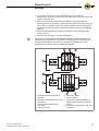
User manual Interroll PowerControl Chapter-ID: User manual Chapter-ID: Version Chapter-ID: Translation of the original instructions Version 1.0 (04/2013) en Translation of the original instructions Manufacturer's address Interroll Engineering GmbH Hoeferhof 16 D-42929 Wermelskirchen Tel. +49 2193 23 0 Fax. +49 2190 2022 www.interroll.com Copyright The copyright of this manual remains with Interroll Engineering GmbH. The operating instructions contain technical regulations and drawings which may not be reproduced partially or in full, transmitted by any means, utilized without permission for competitive purposes or disclosed to third parties. Version 1.0 (04/2013) en Translation of the original instructions PowerControl Table of contents Introduction Information about the operating instructions . . . . . . . . . . . . . . . . . . . . . . . . 2 Warnings in this manual . . . . . . . . . . . . . . . . . . . . . . . . . . . . . . . . . . . . . . . 2 Further symbols . . . . . . . . . . . . . . . . . . . . . . . . . . . . . . . . . . . . . . . . . . . . . 3 Safety General safety instructions . Intended use . . . . . . . . . . . Unintended use . . . . . . . . . Dangers . . . . . . . . . . . . . . . Interfaces to other devices . Qualified persons . . . . . . . . . . . . . . . . . . . . . . . . . . . . . . . . . . . . . . . . . . . . . . . . . . . . . . . . .... .... .... .... .... .... ... ... ... ... ... ... .... .... .... .... .... .... ... ... ... ... ... ... .... .... .... .... .... .... ... ... ... ... ... ... .... .... .... .... .... .... ... ... ... ... ... ... 4 4 4 5 5 5 . . . . . . . . . . . . . . . . . . . . . . . . . . . . . . . . . . . . . . . . . . . . . . . . . . . . . . . . . . . . . . . . . . . . . . . . . . . . . . . . . . . . . . . . . . ... ... ... ... ... ... 6 7 8 8 8 9 Product information Product description . . . . Technical specifications . Dimensions . . . . . . . . . . Type plate . . . . . . . . . . . Scope of delivery . . . . . . Application notes . . . . . . . . . . . . . . . . . . . . . . . . . . . . . . . . . . . . . . . . . . . . . . . . . . . . . . . . . . . . . . . . . . . . . . . . . . . . . . . . . . . . . . . . . . . . . . . . . . . . . . . . . . . . . . . . . . . . . . . . . . . . . . Transport and storage Transport . . . . . . . . . . . . . . . . . . . . . . . . . . . . . . . . . . . . . . . . . . . . . . . . . 10 Storage . . . . . . . . . . . . . . . . . . . . . . . . . . . . . . . . . . . . . . . . . . . . . . . . . . 10 Assembly Attaching the PowerControl to a conveyor . . . . . . . . . . . . . . . . . . . . . . . . 11 Electrical installation . . . . . . . . . . . . . . . . . . . . . . . . . . . . . . . . . . . . . . . . 12 Initial startup and operation Initial startup . . . . . . . . . . . . . . . . . . . . . . . . . . . . . . . . . . . . . . . . . . . . . . 15 Operation . . . . . . . . . . . . . . . . . . . . . . . . . . . . . . . . . . . . . . . . . . . . . . . . . 15 Maintenance and cleaning Warning notices concerning maintenance and cleaning . . . . . . . . . . . . . . 16 Maintenance . . . . . . . . . . . . . . . . . . . . . . . . . . . . . . . . . . . . . . . . . . . . . . 16 Cleaning . . . . . . . . . . . . . . . . . . . . . . . . . . . . . . . . . . . . . . . . . . . . . . . . . 17 Abandonment and disposal Abandonment. . . . . . . . . . . . . . . . . . . . . . . . . . . . . . . . . . . . . . . . . . . . . . 18 Disposal . . . . . . . . . . . . . . . . . . . . . . . . . . . . . . . . . . . . . . . . . . . . . . . . . . 18 Appendix Installation declaration . . . . . . . . . . . . . . . . . . . . . . . . . . . . . . . . . . . . . . . 19 Version 1.0 (04/2013) en Translation of the original instructions 1 PowerControl Introduction Information about the operating instructions Contents Validity of the manual This manual contains important advice, notes and information about the PowerControl in all phases of its lifecycle: • Transport, assembly and start-up • Safe operation, maintenance and troubleshooting, disposal • Accessories The manual describes the PowerControl as it is delivered by Interroll. In addition to this manual, special contractual agreements and technical documents apply to special versions. The manual is part of the product For trouble-free, safe operation and warranty claims, read the manual and follow the instructions before handling the PowerControl. Keep the manual near to the PowerControl. Pass the manual on to any subsequent operator or occupant of the PowerControl. Interroll does not accept any liability for faults or defects due to nonobservance of this manual. If you have any questions after reading the operation manual, feel free to contact our customer service. See the last page for your local contact information. Warnings in this manual The warnings in this document refer to risks which may arise while using the PowerControl. For relevant warnings, see "Safety", page 4 and the warnings at the beginning of each chapter. There are three categories of danger. The following signal words are used in the document as required: • Danger • Warning • Caution Signal word Meaning Danger Indicates a hazardous situation which, if not avoided, will result in death or serious injury. Warning Indicates a hazardous situation which, if not avoided, could result in death or serious injury. Caution Indicates a hazardous situation which, if not avoided, may result in minor or moderate injury. Structure of warnings DANGER Nature and source of the hazard Possible consequence of non-observance Information about how to avoid the hazard. 2 Version 1.0 (04/2013) en Translation of the original instructions PowerControl Introduction Further symbols This symbol identifies possible material damage. Information about how to avoid damage. Important This symbol displays safety instructions. Hint This symbol marks useful and important information. This symbol marks the steps that have to be carried out. Version 1.0 (04/2013) en Translation of the original instructions 3 PowerControl Safety General safety instructions The PowerControl is designed according to the technical state of the art and is reliable in operation, once distributed. However, risks may still arise. • Risks of physical injury to the user or bystanders. • Adverse effects of the PowerControl and other material. Important Disregarding the warnings in this manual may lead to serious injury. Always read the entire operating and safety instructions before starting to work with the PowerControl and follow the information contained herein in full. Only instructed and qualified persons may work with the PowerControl. Always keep this user manual at hand when working on the PowerControl so that you can consult it quickly if required. Always comply with relevant national safety regulations. If you have any questions after reading this user manual, feel free to contact our customer service. See the last page for contact information. Intended use The PowerControl serves as a power supply for the Interroll RollerDrives and their controls. The PowerControl must only be used for industrial applications and in an industrial environment. It must be integrated into a conveyor module or conveyor system. Any other use is considered inappropriate. Any modifications that affect the safety of the product are not permitted. The PowerControl may only be operated within the defined operating limits. Unintended use Applications not according to the intended use of the PowerControl require approval from Interroll. 4 Version 1.0 (04/2013) en Translation of the original instructions PowerControl Safety Dangers Important The following list provides information about the various types of danger or damage that may occur while working with the PowerControl. Bodily injury Maintenance or repair work must only be performed by authorized and qualified persons in accordance with the applicable regulations. Before using the PowerControl, ensure that no unauthorized persons are near the conveyor. Electricity The requirements for electrical equipment of machinery and machine systems (DIN EN 60204-1) must be observed during project planning, installation, operation, maintenance and servicing. Only perform installation and maintenance work after you have switched off the power. Ensure that the power cannot be turned on accidentally. Important Improper handling of system components or working on the installation when it is not in an activated state can result in short dangerous flashovers (fire risk) of > 700 W due to the relatively high power output. Working environment Do not use the PowerControl in areas where there is a hazard of explosion. Remove equipment or material which is not required from the workspace. Faults during operation Regularly inspect the PowerControl for visible damage. Make sure that the operating conditions are observed during the service life and that dangerous operating conditions are eliminated. If you notice smoke, switch off the power immediately and ensure that it cannot be switched on again accidentally. Contact qualified personnel immediately to find the source of the fault. Maintenance Because the product does not require maintenance, you only need to inspect the PowerControl regularly for visible damage and that all cables and screws are firmly in place. Interfaces to other devices By assembling the PowerControl in a conveyor module, further hazards may occur. These hazards are not part of this manual and have to be analyzed during the design, installation and startup of the conveyor module. After assembling the PowerControl in a conveyor module, check the whole system for a new potential dangerous spot before switching on the conveyor. Qualified persons Qualified persons are persons who read and understand the manual and, taking national regulations into account, can competently execute incidental work. Only instructed and qualified persons may work with the PowerControl, taking the following into account: • the relevant manuals and diagrams, • the warning and safety instructions in this manual, • the system specific regulations and requirements, • national or local regulations and requirements for safety and accident prevention. Version 1.0 (04/2013) en Translation of the original instructions 5 PowerControl Product information Product description The PowerControl is a component of the Interroll controller concept. It supplies the Interroll controls with 24 VDC operating voltage and provides the rated power for the RollerDrive. Functions • • • • • • • • • • 6 Providing 24 VDC system voltage Peak load and start-up current for greater performance requirements up to 30 A @ 24 VDC for 4 s IP54 protection rating 100 % duty cycle, maintenance-free, any installation position Self-protection against overload, reverse voltage, short circuit and load drop System compatible due to low cold start current (inrush) and active power factor correction No power reduction (derating) over the entire operating temperature range of the Interroll controls Multiple terminal points on mains and load side; no special connector required Cable entry via M20 fittings including seals, mounted or included CE-compliant Version 1.0 (04/2013) en Translation of the original instructions PowerControl Product information Technical specifications Rated supply voltage Version 1.0 (04/2013) en Translation of the original instructions 400 VAC, 3 phases, PE (no phase grounded, no neutral conductor required) Mains voltage range 380 to 480 VAC ± 15 % Mains frequency 50 to 60 Hz ± 6 % Mains power consumption typically 0.8 A per phase @ 3 x 400 VAC Mains cold start, inrush typically 3 A @ 400 V Rated output voltage 24 VDC ± 0.2 V Rated output power 480 W Rated peak power max. 720 W @ 24 VDC for 4 s, repetition rate depends on duration and actual peak load Maximum output current 30 A @ 24 V for 4 s Ripple/noise 100 mVpp, 20 Hz to20 MHz, 50 Ohm Feedback resistance max. 32 VDC, same polarity; superimposed alternating voltage not permitted Short-circuit current 20 A permanent + max. 15 % (depending on loop impedance) Protection classification 1 (PE) Protection rating IP54 (when installed correctly) Conformity CE (EN 55011, EN 55022, EN 61000-3-2, EN 61000-4-3, EN 61000-4-4, EN 61000-4-5, EN 61000-4-6, EN 61000-4-2) Parallel switching of the output voltage not permitted Permissible ambient temperature in operation -28 °C to 40 °C (-18 °F to 104 °F) Permissible ambient temperature for transport and storage -40 °C to 85 °C (-40 °F to 185 °F) Permissible temperature change DIN EN 60068-2-14 Permissible ambient humidity DIN EN 60068-2-78, 93 % @ 40 °C, noncondensing Installation height above sea level max. 1000 m (max. 3300 ft) Installation position any Mechanical stress DIN EN 60068-2-6, DIN EN 60068-2-27 Weight approx. 2.5 kg (5.5 lbs) Dimensions see page 8 Box Plastic (ABS), RAL 7035 7 PowerControl Product information Dimensions 34 ±5 110 55 ø4.2 SW24 ø8 4 x ø4.2 200 230 (297) 4.5 ø6-13 288 25 300 86.5 Type plate The information on the label is used to identify the PowerControl. PowerControl for RollerDrive Interroll Engineering GmbH 42929 Wermelskirchen · Germany www.interroll.com Ser. Nº: 000000372 · Art. Nº: 1004029 Production week/year: 09/12 Protection classification: IP54 Mains Input: 3 ph; 380 – 480 VAC; ± 15% Frequency: 50 – 60 Hz Input current: 0.9 – 0.65 A/Phase Power factor: 0.94 Peak inrush current: 4 A; 1 A²s Output Voltage: 24 VDC Total nominal current: 20 A Peak current: 30 A; max. 4 s Scope of delivery The PowerControl contains the following components: • PowerControl • 2 seals for M20 screw connection, suitable for round cable diameter 6 13 mm • Connector cable, pre-assembled for grounding the minus pole, 2.5 2 mm, green-yellow The mounting screws for attaching the PowerControl are not included in the delivery. 8 Version 1.0 (04/2013) en Translation of the original instructions PowerControl Product information Application notes The following information is intended to assist operators use the PowerControl. This information may not be complete. In specific cases, it must be examined to what extent the actual conditions under which this information is applicable. The applicable safety and installation rules at the respective operating location take precedence. Grid-side connection and fuse protection The PowerControl does not contain any internal instrument fuses. Due to the operating principle of the power supply, overloads on the load end are not transferred to the mains connection. The appropriate grid-side protective devices would therefore be ineffective. The dimensions of the grid-side fuse(s) can focus on the line protection. If, only a PowerControl is connected after the fuse, it will work with a minimum protection from circuit breaker B6 or C3 (limiting current integral 1A²s). To ensure full performance of the PowerControl, the use of a phase monitor or chained fuses is recommended on the grid side. Hint A longer/more permanent operation of the PowerControl with only two phases is not permitted. Load-end connection and fuse protection It is basically impossible for the PowerControl to be destroyed by an overload. For this reason, the PowerControl does not require any load side fuses to protect the device. In case of an overload, the output voltage fails – in extreme cases to 0 V and the PowerControl limits the load current automatically to 20 A (projected value +15% max.). After the overload condition is eliminated, the normal operating state is resumed automatically. The automatic mode change of the PowerControl from constant voltage to constant current mode in case of overloading allows the load circuit to be designed without using an additional line protection, taking into account the requirements of EN 60204-1 and DIN VDE 0298-4. Conveyor with multiple PowerControl If the required performance exceeds the maximum capacity of a PowerControl, then the use of a second PowerControl is needed. The parallel connection of the load terminals of two or more PowerControl is not permitted. All PowerControls must be powered up at the same time, otherwise the Interroll Controls can fail to initialize. (refer to notes in the operating manuals for the respective Interroll controls). To simplify installation, the mains connection can be daisy chained. For this purpose, each PowerControl has an additional terminal space and additional M20 cable screw connection for connecting an additional PowerControl. During project planning, observe the relevant requirements with respect to the load capacity of the feed line, fusing and switching requirements. Connecting the ground of the load connection terminal block with PE flat plug (grounding, PELV) in the PowerControl ensures a sufficient ground equalization between the supply areas when the PE is installed correctly. This potential compensation must not be used in operation as PE (protective earth). No socalled ground loops must be created as a result of improper power line installation. Version 1.0 (04/2013) en Translation of the original instructions 9 PowerControl Transport and storage Transport • Every PowerControl is packaged in its own cardboard box. There is a risk of damage to property if transported incorrectly. Only qualified and authorized persons should transport the product. Follow the instructions below. Do not stack more than four cardboard boxes on top of each other. Check that the boxes are correctly fixed in place prior to transport. Avoid serious impacts during transport. Check every PowerControl for visible damage after transport. In the event of damage, take photos of the damaged parts. To maintain the warranty, report any damage caused by transport instantly to the transport company and Interroll. Do not expose the PowerControls to serious temperature fluctuations as this could result in condensation. Storage CAUTION Risk of injury due to improper storage Do not stack more than four carton boxes on top of each other. Check each PowerControl for damage after storage. 10 Version 1.0 (04/2013) en Translation of the original instructions PowerControl Assembly Attaching the PowerControl to a conveyor The PowerControl is attached to the conveyor frame with 4 screws (diameter 4 mm, not included with delivery). Screw type and length depend on the mounting surface. M4 cylinder head screws are recommended. Risk of damage leading to failure or shortened life expectancy Check each PowerControl visually for damage before assembly. Make sure that the housing is not warped during installation (no bending or torsion). Do not mount the PowerControl above heat sources. Ensure there is always natural air circulation around the unit. Do not drill additional mounting holes in the casing or enlarge the holes provided. Do not drop the PowerControl to prevent internal damage. Hint The IP54 protection rating can only be ensured when installation is performed properly. Locate a flat surface for mounting the PowerControl. Make sure that there enough space to remove the cover and the inlet and outlet of the power and load cables. Note the bending radius of the cables when doing so. Remove the PowerControl cover. Use the PowerControl as a template and mark the center of the four mounting holes. For the distance between the holes, see "Dimensions", page 8. Drill four mounting holes with ø 4 mm bit on the markings. Fasten the PowerControl. Make sure that the screws cannot loosen due to vibration or shock and that no warping inside the casing has occurred. Version 1.0 (04/2013) en Translation of the original instructions 11 PowerControl Assembly Electrical installation All cable screw connections are of the type M20. To simplify attachment of the cables, they can be removed from the housing. No wrench is required for loosening and tightening the nuts. In its as-delivered state, the screw connections for the mains connection contain O-ring seals for cables with an outer diameter 6 to 13 mm. One screw connection also contains a removable dust guard. The screw connections for the load connection contain profile flat cable seals. Stranded wires should be used for the cables. These can be clamped directly without a ferrule (max one conductor per terminal point). DANGER Danger to life from electrical shock All electrical work should only be performed by qualified and authorized persons. Disconnect the system from power supply before installing, removing or rewiring the PowerControl. Ensure that both during operation and in case of errors no hazardous voltage can access the connections or the housing. Do not expose cables to excessive strain, pressure or bending. Bending the cable can cause damage to the insulation. Switch on the operating voltage only once all cables are connected and the cover of PowerControl is attached. Risk of damage to the PowerControl Only use cables with the right dimensions for the specific conditions, particularly with respect to crosssection and insulation. When opening the housing, make sure that no dust or dirt can collect inside the housing. Ensure that the RollerDrive, the control and the PowerControl are connected to the conveyor frame or supporting structure in such a way that they are properly earthed. Incorrect earthing can result in the build-up of static charge, causing the motor or control to malfunction or fail prematurely. Guide the cable through the screw fitting located closest to the respective terminal. If necessary, turn the profile cable seals 180° to match the orientation/polarity of the cable. If the load is not connected via the profile flat cable, replace the profile flat cable seal with a seal appropriate for the cable type being used. O-seals for round cables with a sheath diameter of 6 to 13 mm are included with the delivery. 12 Version 1.0 (04/2013) en Translation of the original instructions PowerControl Assembly If the mains connection is to be guided through for an additional PowerControl, remove the dust cap on the appropriate screw connection. Do not pierce the dust cap. Ensure that all screw connections are available and provided with the appropriate seals. If necessary, replace defective screw connections with new ones. Use only size M20 screw connections together with the housing that guarantee a protection rating of at least IP54 without requiring an additional seal ring. Strip lines appropriately and remove the insulation along the appropriate length of the line. Connect lines as shown in the terminal diagram. Hint Terminals of the type WAGO-TOPJOB are installed in the PowerControl. The manufacturer's instructions for assembly and releasing the line connections for this type of terminal must be observed. The WAGO TOPJOB tool or other appropriate tool must be used to actuate the terminals. 1 2 3 4 Version 1.0 (04/2013) en Translation of the original instructions Terminal block load connection (24 VDC) Earthing of the terminal block, load connection Terminal block power supply (400 VAC) Connector, load 1 5 6 7 8 Connector, load 2 Comb bridges Connection, mains for additional PowerControl (Looping through the 400 V) Connection, mains (400 V; PE and 3 phases) 13 PowerControl Assembly Hint • • • • • • The PE conductor must always be connected. The clamping of the phases must match the labeling on the terminals. If a 5-pin cable with accompanying neutral conductor is used for the power supply, it must be installed in the device in such a way that no contact is possible with any other operational part that is energized or conductive. The comb bridges in the load connection terminal block must not be removed. To provide a protective extra low voltage (PELV) in accordance with EN 60204-1, the connecting line included with the delivery must be connected with the earth of the load connection terminal block and the PE flat plug (earthing) (see terminal diagram). Without this connection, none of the poles of the load connection terminal block will be connected to the earth (complete galvanic isolation). Providing PELV is absolutely necessary when using Interroll ZoneControl or ConveyorControl. Hint The switching state PELV must be lifted while performing an isolation test. The operator is responsible for ensuring that the correct switching state restored afterwards. If necessary, perform any additional tests after mounting and installation and before switching on for the first time as required by the applicable regulations at the location of use. Reattach the cover to the housing and screw down. 14 Version 1.0 (04/2013) en Translation of the original instructions PowerControl Initial startup and operation Initial startup Checks before initial startup Pre-commissioning checks Ensure that the PowerControl has been correctly fastened to the profile and that all screws have been correctly tightened. Ensure that there are no additional areas of danger caused by interfaces to other components. Ensure that the wiring is in accordance with the specification and legal directives. Check all protection devices. Ensure that no bystanders are in dangerous areas around the conveyor. Check the PowerControl for visible damage. Make sure that the cover is attached and all screw connections are in place. Check all protection devices. Ensure that no bystanders are in dangerous areas around the conveyor. Operation CAUTION Accidental start-up of the RollerDrive Danger of crushing of limbs and damage to goods Ensure that no unauthorized persons are near the conveyor before switching on the operating voltage. Hint Ambient conditions during operation see "Technical specifications", page 7 The PowerControl delivers the 24 V system voltage as soon as the power supply is switched on. Version 1.0 (04/2013) en Translation of the original instructions 15 PowerControl Maintenance and cleaning Warning notices concerning maintenance and cleaning CAUTION Risk of injuries due to incorrect handling Maintenance work and cleaning must only be performed by qualified and authorized persons. Perform maintenance work only after switching off the power. Ensure that the system cannot be switched on accidentally. Set up signs indicating that maintenance work is in progress. Maintenance Inspecting the PowerControl The PowerControl itself is maintenance-free. For avoidance of faults however, regular inspection of the connections and fixings is recommended. As part of regular inspection and maintenance on the conveyor, also check the PowerControl in accordance with the legal requirements applicable at the location of use. Observe the following items in particular: – proper functioning of the protective ground connector – ensuring proper isolation – all cable connections and screw connections tightly in place – general integrity of all components For isolation tests, the following test voltages are permissible: • 24V DC (+) and (-) shorted/PE: max. 500 VAC, 5 s • L1, L2, L3 shorted / PE: max. 2000 VAC, 5 s Replacing the PowerControl If a PowerControl is damaged (e. g. soaked by corrosive liquids from transport goods, cracks or breaks in the casing, etc.), it must be immediately disconnected from the mains, labeled as defective and replaced. This also applies to all the cables and screw connections. Install a new PowerControl (see "Abandonment", page 18 and see "Attaching the PowerControl to a conveyor", page 11). If the PowerControl is removed from the line-side interconnection, make sure that the open terminal points are appropriately protected. Take particular care to ensure that the PE connection remains in compliance with standards. 16 Version 1.0 (04/2013) en Translation of the original instructions PowerControl Maintenance and cleaning Cleaning As per protection rating IP54, the PowerControl is resistant to dirt and liquids. Under normal conditions, no cleaning for functional reasons is required. However, if cleaning does become necessary, vacuum out or use a damp cloth to wipe the housing. Do not use detergents or solvents. If you need to open the housing, make sure when opening the housing that no dust or dirt can collect inside the housing. Hint If dirt particles, liquids or small parts (wire cuttings, screws, etc.) get inside the power supply or in the terminals, the PowerControl must not continue to be used. This applies in particular to liquids, even if these drain out again or have dried. DANGER Danger to life from electrical shock Do not use a screwdriver, wire or similar object to remove foreign particles in the power supply or in the terminals. Version 1.0 (04/2013) en Translation of the original instructions 17 PowerControl Abandonment and disposal Abandonment CAUTION Risk of injury due to improper handling Abandonment may only be executed by qualified and authorized persons. Only abandon the PowerControl after switching off the power. Ensure that the PowerControl cannot be turned on accidentally. Disconnect all cables from the PowerControl. Unscrew the screws attaching the PowerControl to the conveyor frame. Extract the PowerControl from the conveyor frame. Disposal The operator is responsible for the proper disposal of the PowerControl. In doing so, industry-specific and local provisions must be observed for the disposal of the PowerControl and its packaging. 18 Version 1.0 (04/2013) en Translation of the original instructions PowerControl Appendix Installation declaration in accordance with the EC Machinery Directive 2006/42/EC, Appendix II B, the manufacturer: Interroll Engineering GmbH Hoeferhof 16 D - 42929 Wermelskirchen Germany hereby declares with sole responsibility that the product range • PowerControl is not a ready-to-use machine as defined by the EC Machinery Directive and, therefore, does not fully comply with the requirements of this directive. The commissioning of these conveyor modules is not permitted unless conformity of the entire machine/system in which they are installed has been declared in compliance with the EC Machinery Directive. The health and safety requirements as stated in Appendix I have been applied. The special technical documents mentioned in Appendix VII B have been prepared and will be sent to the responsible authority if necessary. Person authorized to prepare the technical documents: Georg Malina, Interroll Engineering GmbH, Hoeferhof 16, D - 42929 Wermelskirchen Applied EC Directives: • Machinery Directive 2006/42/EC • EMC Directive 2004/108/EC • RoHS Directive 2002/95/EC Applied harmonized standards: • EN ISO 12100 Parts 1 and 2 "Safety of machinery - Basic concepts, general principles for design" - Part 1: "Basic terminology, methodology" Part 2: "Technical principles" Wermelskirchen, 1 March 2013 Armin Lindholm (Managing Director) (This declaration can be obtained at www.interroll.com, if needed.) Version 1.0 (04/2013) en Translation of the original instructions 19 Europe Norway Austria Tel + 49 2193 23 187 [email protected] Interroll A/S Kobbervikdalen 65 3036 Drammen Norway Tel + 47 32 88 26 00 [email protected] Belgium Tel. + 49 2193 23 259 [email protected] Czech Republic Interroll CZ, s.r.o. Na Řádku 7/3172 69002 Břeclav Czech Republic Tel + 420 519 330 210 [email protected] Denmark Interroll Nordic A/S Hammerholmen 2-6 2650 Hvidovre Denmark Tel + 45 36 88 33 33 [email protected] Poland Interroll Polska Sp. z o.o. ul. Płochocińska 85 03-044 Warszawa Poland Tel + 48 22 741 741 0 [email protected] Portugal Rulmeca de Portugal, LDA Parque Industrial do Tortosendo Edifício Parkurbis, Loja 7 Apartado 113 6200-865 Tortosendo Portugal Tel + 351 275 33 07 80 [email protected] Romania Finland Interroll Nordic A/S Martinkyläntie 53 01720 Vantaa Finland Tel + 358 9 54 94 94 00 [email protected] Krako International SRL Str. Sfanta Maria 1-5 Bl. 10A4 Sc 1 Apt 4 Sector 1 001494 Bucuresti Romania Tel + 40 21 260 2050 [email protected] France Interroll SAS Z.I. De Kerannou-BP34 29250 Saint-Pol-de-Leon France Tel + 33 2 98 24 4100 [email protected] Germany Interroll Fördertechnik GmbH Höferhof 16 42929 Wermelskirchen Germany Tel + 49 2193 23 0 [email protected] Hungary Lörincz Kft. Kastély U.27 Pf. 57 2045 Törökbálint Hungary Tel + 36 23 337 891 [email protected] Iceland IBH ehf Dugguvogur 10 104 Reykjavik Iceland Tel + 354 562 6858 [email protected] Italy Rulli Rulmeca S.P.A. Via Arturo Toscanini 1 24011 Almé (Bg) Italy Tel + 39 035 43 00 111 [email protected] Luxembourg Tel + 49 2193 23 259 [email protected] Netherlands Tel + 49 2193 23 151 [email protected] Slovenia 3-TEC, prehrambenatehnologija-hlajenje Dravska ulica 7 1000 Ljubljana Slovenija Tel + 386 1 56 56 370 [email protected] Spain Interroll España S.A. Parc Tecnològic del Vallès C/Dels Argenters, 5 Edificio 1 Bp y Cp 08290 Cerdanyola del Vallès Barcelona Spain Tel + 34 90 211 0860 [email protected] Sweden Interroll Nordic A/S Karlsrovägen 64 302 41 Halmstad Sweden Tel + 46 35 227 077 [email protected] North and South America Canada Interroll Checkstand 8900 Keele Street Unit 2 & 3 Concord, Ontario L4K 2N2 Canada Tel +1 905 660 4426 [email protected] USA Singapore Interroll Corporation 3000 Corporate Drive Wilmington, N.C. 28405 USA Tel +1 910 799 1100 [email protected] Interroll (Asia) Pte. Ltd. 386 Jalan Ahmad Ibrahim Jurong 629156 Singapore Republic of Singapore Tel + 65 6266 6322 [email protected] Interroll Automation LLC 5035 Keystone Boulevard Jeffersonville, IN 47130 USA Tel +1 812 284 1000 [email protected] Sri Lanka Interroll Dynamic Storage, Inc. 232 Duncan Circle Hiram, GA 30141 USA Tel +1 770 943 15 41 [email protected] Brazil Interroll Logística Elementos para Sistemas Transportadores Ltda Rua Dom João VI 555 - Parque Industrial SA Pindamonhangaba - SP CEP 12412- 805 Brazil Tel + 55 (0)12 3648 8021 [email protected] Asia India Interroll Ltd. Brunel Road Corby, Northants NN17 4UX United Kingdom Tel + 44 1536 200 322 [email protected] Interroll Drives and Rollers India Pvt. Ltd. No. 276, 4th main, 4th phase Peenya Industrial Area Bangalore-560058 India Tel + 91 080 41272666 [email protected] Version 1.0 (04/2013) en Translation of the original instructions Colombo Machinery & Equipment Ltd. No: 102, Fife Road Colombo 05 Sri Lanka Tel + 94 11 250 0078/79 [email protected] Taiwan First Auto-Transfer Equipment Co. Ltd 8F-3, No: 65, Song De Road Hsin Yi District Taipei 11076 Taiwan Tel + 886 2 27 59 88 69 [email protected] Thailand Interroll (Thailand) Co. Ltd. 700/685, Moo 1 Amata Nakorn Panthong, Chonburi 20160 Thailand Tel + 66 3 844 7448 [email protected] China United Kingdom Interroll South Africa (Pty) Ltd Box 327 Isando 1600 Gauteng South Africa Tel + 27 11 281 99 00 za sales@interroll com Korea Interroll (Korea) Co. Ltd. Rm 301 Dongsan Bldg. 333-60 Shindang-Dong 100-826 Choong Ku, Seoul Tel + 82 2 2231 19 00 [email protected] Switzerland Tel. + 49 2193 23 190 [email protected] South Africa Interroll Japan Co. Ltd. 302-1 Shimokuzawa Midori-ku Sagamihara-shi Kanagawa 252- 0134 Japan Tel + 81 42 764 2677 [email protected] Interroll Canada Ltd. 1201 Gorham Street Newmarket Ontario L3Y 8Y2 Canada Tel +1 905 727 33 99 [email protected] Interroll (Suzhou) Co. Ltd. Block B & C Ecological Science Hub No. 1 Ke Zhi Road Suzhou Industrial Park Jiangsu Province China Postal Code: 215021 Tel + 86 512 62560383 [email protected] Africa Japan Australia and New Ze aland Australia Interroll Australia Pty. Ltd. 70 Keon Parade Thomastown Victoria 3074 Australia Tel + 61 3 94 60 21 55 [email protected] New Zealand Automation Equipment (NZ) Ltd. 26 Tawn Place, Pukete, Hamilton New Zealand Tel + 64 (7) 849 0281 [email protected] Israel Comtrans-Tech Ltd. P.O.B. 17433 Tel-Aviv 61174 Israel Tel + 972 54 4272747 [email protected] Headquarter Interroll (Schweiz AG) + 41 91 850 25 25 [email protected] www.interroll.com