1
BVIR User Manual
VERSION:2.0
NEWARE TECHNOLOGY.LIMITED
www.neware.com.cn
+86-755-83108866
Note, Tip and Cautions
NOTE:A NOTE indicates important information that helps you make better use of device.
TIP:A TIP indicates either potential damage to hardware or loss of data and tells you how to avoid
the problem.
CAUTION:A CAUTION indicates a potential for property damage, personal injury, or death.
Please Note:This manual describes how to better use the system operation of device, please reading thoroughly
before doing the system operation. The updated information in this manual is subject to change without notice
due to operation maybe different if the system is upgraded at a later time. Please always state the version No. xx
indicated in the cover page for any question you may have.
© 2010 NEWARE。All rights reserved.
Reproduction in any manner without the written permission of NEWAE Ltd. is strictly forbidden.
March 2010
VERSION:2.0
To Customers:
Thank you for your concern and support to “NEWARE” brand series products!
Before using this system, please read this user manual seriously in order to use the system more
better. For the continuously upgrading, please refer to the latest version and this version is only
for reference.
We are committed to supplying high-quality product of battery formation, grading and
testing device. During more than 10 years development, our product has passed strict inspection
and obtained a number of certifications. We have accumulated more than 8000 business partners
throughout institutions, government departments, enterprises and trading companies. NEWARE
Technology Ltd. has become the industry mainstream supplier with customer admitted.
Shenzhen NEWARE Technology Ltd has passed the ISO9001: 2000 quality management
system certification, registered “NEWARE” trademark, and adopted global advanced SAP
software system as company business processes management platform. In order to achieve
sustainable development, NEWARE now is on its way to cut down our carbon emissions. At the
same time we are pursuing an optimal service both from better performance against with lower
cost product and perfect after-sales service to meet customer’s various needs.
Under the advanced integrated project management system, our software has achieved
CMMI 3 level. It guaranteed the consistency between the development and the production.
Solved the customer’s special needs.
For any operation problems, please have no hesitate to contact our service line:
800-830-8866, our technical supporting engineer will work out proper solutions for you.
Browse more type of models, download and upgrade your software and consult information
please visit our website:http://www.neware.com.cn。
BVIR User Manual
CONTENTS
1 INTRODUCTION ..............................................................................5
1.1 INSPECTION............................................................................................. 5
1.2 SECURITY................................................................................................. 5
1.3 OVER-PRESSURE CATEGORY ............................................................ 5
1.4 PRECAUTION........................................................................................... 6
2 OVERVIEW ........................................................................................7
2.1 OVERVIEW ............................................................................................... 7
2.2 APPLICATIONS........................................................................................ 7
2.3 TECHNICAL SPECIFICATIONS ........................................................... 7
3 STRUCTURE......................................................................................9
3.1 BUTTONS .................................................................................................. 9
3.2 SCREEN ..................................................................................................... 9
3.3 LED INDICATORS ................................................................................. 10
4 MEASURING PROCEDURE .........................................................11
4.1 PREPARATION........................................................................................11
4.2 STANDARD MEASURING PROCEDURE.......................................... 12
4.3 COMPARISON ........................................................................................ 12
4.4 START/SHUTDOWN THE BUZZER ................................................... 13
4.5 HOLD........................................................................................................ 13
4.6 VIEW HISTORY DATA.......................................................................... 14
4.7 CALIBRATION ....................................................................................... 14
4.8 BATTERY SHORTAGE TIPS................................................................ 15
4.9 SHUTDOWN AUTOMATICALLY ....................................................... 15
APPENDIX...........................................................................................16
OPERATION NOTICES............................................................................... 16
HOW TO MAINTENANCE ......................................................................... 16
AFTER SALES SERVICE............................................................................ 17
SERVICE ITEMS ..................................................................................................... 17
EXCEPTION ............................................................................................................ 17
REPLACEMENT ..................................................................................................... 17
CUSTOMER OBLIGATION.................................................................................... 17
CONTACT NEWARE ................................................................................... 19
4 | CONTENTS
BVIR User Manual
1 INTRODUCTION
Thank you for choosing our product, In order to make your operation more
convenient, please read this manual before using.
1.1 INSPECTION
When you get this product, please check it over if there is any problem in the transportation.
Especially the accessory, included panel buttons and the wire. If there is obvious damage, or does
not work in accordance with the instructions, please contact the NEWARE sales engineer.
Accessory
a manual
4 test pen or polymer fixture
a recharger
100mΩ standard resistance
Transportation
To make use of the original packing materials the company provided in the
transportation to avoid unnecessary losses.
1.2 SECURITY
Danger
This product is designed in accordance with relevant safety standards, and passed the safety tests
before transportation. But using the equipment in the wrong way will be harmful to the human
body; the equipment will also be damaged. Before using make sure you are in accordance with
the order of the operating manual and the operating environment.
Notations Used in This Manual
The following instruction of warning and note are representative important
in the manual.
“WARNING”
The warning is to alert you to the possibility of a dangerous safety condition that
could result in damage to the NEWARE equipment, damage to the battery under test,
or very serious injury or death to you and surrounding people
“CAUTION”
The Caution message is to alert you to potential conditions less severe than the
Warning, but where damage could still occur.
“NOTE”
A Note shows key information, an easier way to do something, or provide a better
4understanding of what is being presented.
“TIP”
A Tip is to inform you of an alternate method or a good idea.
1.3 OVER-PRESSURE CATEGORY
This product meets the class I over-pressure measurement of product standard. In order to ensure
the safe operation of measurement product , IEC 60664 has established a safety standards for
variety of electrical environment, from CAT I to CAT IV is divided into four categories, called
over-pressure standards. They are defined as follow:
CAT I: Through a transformer or similar electrical circuit connected to the AC outlet on the
secondary electrical circuit.
CAT II: Directly connected to the AC power output devices on the electrical circuit. (Portable
tools, home appliances, etc.)
INTRODUCTION ︱ 5
BVIR User Manual
CAT III: Connected to the electrical circuit of the distribution box on the heavy equipment ,
which from the distribution box to the DC circuit of the AC outlet.
CAT IV: Introduced from the introduction of overhead line to line, meter, leakage current
protection device (distribution box).
The high level classification corresponding of high instantaneous electrical energy through it, so
if an equipment design to meet the CAT III environment, it can withstand the more instantaneous
energy than CAT II standards. If an excessive measuring device is used at a higher standard of
environment, it will have a serious accident, which must be avoided.
1.4 PRECAUTION
Warning
1.
2.
The following precaution content is to ensure the operations security that
all of the function of this device can be used under the features. The
maximum voltage between input and ground is 25V AC / DC, do not try to
measure the ground voltage more than 25V.
Ensuring adequate ventilation, when measuring the battery. When the
measurement electrode contact the battery electrode, it maybe produce sparks
also the flammable gas such as hydrogen.
Caution
1.
2.
3.
Verify that the power terminals and measuring terminals connected correctly.
To avoid damage equipment, do not attempt to measure more than 25V of
AC/DC voltage.
Do not try to plus a voltage on the power positive (SOURCE+) terminal and
measuring (SENSE+) terminal or power negative (SOURCE-) terminal and
measurement negative (SENSE-) terminal, which can damage equipment.
Note
1.
2.
3.
This device is not waterproof or dustproof. To avoid damage, do not use in
wet and dusty environments.
Before using this product, make sure the insulating wire is not damaged, and
the pen is not exception exposed, please change a new model table pen when
electric shock in this case.
Do not use the device in the sun, heat, moisture and fogging which the
product may be damaged, and the product insulation deterioration, it will not
meet the design requirements of performance.
Tip
1.
2.
Accurate measurement is basically impossible implementation in magnetic
interference, as in the transformer accessories, big or strong electromagnetic
current to the places (such as radio stations).
Using the distribution measurement pen or fixture in measurement
Service
1.
2.
When you first use this product, verify that the equipment is working
properly, confirm that during the transport or storage the equipment is not
damaged. If you find any problem, contact your sales representative of the
NEWARE.
When sending product rework, please remove the batteries to prevent damage
during transport. Add cushions in the box to prevent shaking during transport.
Be sure these details of the product, the NEWARE will not bear the loss
arising during transport.
6 | INTRODUCTION
BVIR User Manual
2 OVERVIEW
2.1 OVERVIEW
BVIR battery voltage and inter-resistance testing was specifically designed for testing the
inner-resistance of secondary battery, lead-acid cell, nicked-cadmium cell, lithium battery, as
well as testing the open circuit voltage.
2.2 APPLICATIONS
Complicated comparison: BVIR can compare the testing inner-resistance and voltage value
with the presetting inner-resistance and voltage.
Edit and view data: 99999 groups of data can be stored in BVIR, provide a convenient way
to edit and view the measuring data.
Calibration: there are zero calibration and full range calibration.
Shutdown automatically: save power by shutdown automatically, the default time is half
hour after using.
Low battery prompting: BVIR will prompt user when battery is low.
2.3 TECHNICAL SPECIFICATIONS
Indicators Project
indicator parameter
Measuring method
Voltage Range
Voltage
Accuracy
Measuring in AC power
0~20V
Measurement range
Resistance
Accuracy of component
process range
A/D mode
Test frequency
Sampling rate
Response time
Open terminal
Power
USB I/F
Frequency
Preheating
Limit voltage
0.1%
20mΩ\200mΩ\2000mΩ there automatic/
Manual switch
0~200mΩ
1%
200mΩ
~
3%(excluding 200mΩ)
2000mΩ
SAR 12-bit successive comparison method
1KHz
1000groups/S
Display refresh5/S
AC5V(RMS)
<2W
USB 2.0 Full Speed
3 minutes
25V
Requirements of equipment work environment
Indicators Project
indicator parameter
Operating temperature range
Storage temperature range
Operating humidity range
Relative humidity range storage
environments
Use of premises
0℃~40℃
-10℃~50℃
30% ~ 80% RH(No condensation)
30% ~ 90% RH(No condensation)
Both indoor and outdoor, easy carry
OVERVIWE︱ 7
BVIR User Manual
Fixtures and equipment size specifications
Indicators Project
Accessory
Indicator parameter
4 test pen or polymer fixture
Volume
Weight
W*D*H: 120*75*25(mm)
About 0.5Kg
8 |OVERVIEW
BVIR User Manual
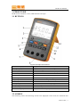
3 STRUCTURE
BVIR consists of buttons, screen, LED indicators and a pen.
3.1 BUTTONS
1 Resistance display
2 Voltage display
3 LEDs lamp
4 Hold key
5 Buzzer key
6 Cursor key
7 Positive pole sense terminal
8 Negative pole sense terminal
9 Value keys
10 Comparing button
11 Adjusting button
12 LEDs lamp
13 Record data group number
Figure1 the shape of the device
Display the measurement of the resistance
Display the measurement of the voltage
Show the battery pass the test
Lock the current contents screen and query historical data
open or shutdown buzzer
Move the cursor to the left position
The interface connecting the sense pen
The interface of connecting the source pen
Increase the value
switch the current mode to comparing mode
The zero and span calibration
Show the battery fail test
Display the record data group numbers
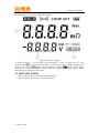
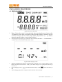
3.2 SCREEN
The measuring values and measuring account were displayed on the screen, the maximum and
STRUCTURE | 9
BVIR User Manual
minimum value of inner-resistance and voltage as well as the group numbers were displayed on
the screen when it is under the comparison interface.
Figure1 The screen of BVIR
As shown in Figure1, ① is the value of inner-resistance, ② refer to voltage value, ③ is the
is the unit of inner-resistance, V is the unit of voltage, “HOLD” appears when
record account,
the screen is locked,
appears when the buzzer is opened.
stands for the battery
capacity, “min”, “max” and “MEMO” appears under the compassion application, “DATA” appears
while editing and viewing the data record.
3.3 LED INDICATORS
√
×
when it lights up, it means the comparison has passed.
when it lights up, it means the comparison is failed.
10 | STRUCTURE
BVIR User Manual
4 MEASURING PROCEDURE
4.1 PREPARATION
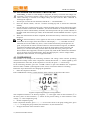
Figure3 the screen after boot
1.
Figure 3 show the screen in 3 seconds after there pressing the power button, after
3 second the screen show as Figue4, at this point the voltage is beating, wait for
2 minutes warming-up time the screen voltage stability, adjustment the “↑”,“↓” button,
change the group number view the historical data
2.
Join the pen or the polymer jig, connect the four terminals, SOURCE + / - and the SENSE + /
-,Figue4 shows not connected to the battery status.
1.
2.
3.
Figue4 stable display screen
When the “
”symbol appears, it illustrate that the battery is low, so please charge it; if the
battery has been rest more than 1 weeks, you’d better charge it to 2 grid power and then go
on to rest it.
” will flash until the battery is full, “
”means the battery is
In the charging process, “
full.
After charging, plug out the charger, and disconnection the instrument.
MEASURING PROCEDURE | 11
BVIR User Manual
4.2 STANDARD MEASURING PROCEDURE
1.
2.
3.
4.
CAUTION:In order to avoid damage to equipment, do not try to measure the voltage over
25AC/DC; not measure constant voltage source; after measuring the high-voltage battery,
while continuing to measure low-voltage battery, the pen must be short connected to
discharge the capacitor
Join the pen, connect the four terminals, SOURCE + / - and the SENSE + / -.
Press the “Power” button, wait for 3 minutes warming-up time to ensure the instrument
stability.
Use the red pen to connect positive pole, and use the black pen to connect the negative pole,
external terminal connected to “SOURCE”, the internal terminal are connected to “SENSE”.
When pen contact with the battery electrode, downward pressure the pen, so that reduction to
the table inside the terminal pen inside, all the SOURCE and the SENSE terminal is a good
contact.
When the measurement has been completed, disconnect the battery connection, and turn off
the power.
NOTE: In the measurement, if “OF” appears on the screen, it said that resistance or voltage
exceeds the device range; when the resistance value display "- - - -", it said that can not be
measured, the circuit breaker may exist t, or the contact between the pen and pole are not
good, it may be due to contact resistance relative to the measurement range too; In addition
to automatic shutdown mode, please do not press the power button at the same time, and
other keys, in case the same time, press the Power key and other keys, please press the
Power button Close equipment, continue to operate may make all the calibration information
is lost, no longer correct measurements; when the table open pen, a sensor voltage will be
displayed in the instrument, it is not equipment failure.
4.3 COMPARISON
This function is to compare the measuring resistance and voltage values and the presetting
resistance and voltage values. If the comparison is failed, then the red “×” will be lighted up, and
the opened buzzer will works; If the comparison is success, the green “√” will be lit up.
In the measuring interface, press the “COMP” button to open and shutdown the comparison
function. When “COMP” symbol appears on the screen, it means this function is working.
Follow the steps shown below for changing the parameters:
1. Enter the comparison interface
Press COMP button at least 3 seconds until the “SET” appears on the right of the screen.
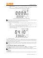
Figure5 Comparison parameters setting interface
The comparison interface is as shown as Figure5, ① is the upper value of inner-resistance,② is
the lower value of inner-resistance, ③ stands for the present setting is inner-resistance or the
voltage, ④ is the comparison group.
2. Set the comparison group
In the comparison interface, press “←”, “→” to move the cursor to the group setting place, press
“↑”, “↓” to change the group number, the maximum is 10, the minimum is 1.
3. Set upper and lower inner-resistance values
12 | MEASURING PROCEDURE
BVIR User Manual
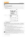
a.
b.
Press “→” to move the cursor to the highest position of inner-resistance maximum,
refers to Figure6.
Press “←”, “→” button to switch between the setting values, press “↑”, “↓” to
increase and decrease the setting values within in 0m to 2000mΩ.
Figure6 inner-resistance upper and lower value setting
4.
Tip: the upper value must be bigger than the lower value, at least be equal, the logical
relationship of compare voltage and resistance condition is “and”.
Set upper and lower voltage values
a. Press “→” to move the cursor to the highest position of voltage maximum, refers to
Figure7.
b. Press “←”, “→” button to switch between the setting values, press “↑”, “↓” to
increase and decrease the setting values within in 0V to 20V.
c. Change the group value to set comparison values of other groups, the previous value
will be set automatically.
Figure7 upper and lower voltage setting
5. Complete the setting
After all the setting has been finished, press “COMP” button to quit, if press “POWER” button to
quit, that will lead the save failure, if forget to press any button, the instrument will turn back to
the comparison interface after 1 minutes rest.
Tip: before pressing “COMP”, all the values are stored in the memory, the setting values
will be stored in hard disk until pressing “COMP” button, pressing other button to quit is
useless.
4.4 START/SHUTDOWN THE BUZZER
The buzzer works when the comparison is failed, press “
” to start/shutdown the buzzer.
”symbol appears indicate the buzzer is working, otherwise, it is shutdown.
When “
Tip:There will be a short buzzer when press any button no matter the buzzer is started or
not.
4.5 HOLD
This function can hold the current interface and remain the same, press “HOLD” button to hold or
MEASURING PROCEDURE | 13
BVIR User Manual
release this function, when “HOLD” appears on the screen, that mean this function works.
Tip:It is only used in the measuring status, in that case only “POWER” and “HOLD” button
will be still on work. You should press this button for less than 3s, otherwise, it will enter in
the “history data view” interface.
4.6 VIEW HISTORY DATA
This instrument can store 99999 groups of measurement data, user can view and edit data, follow
the operations below:
1. In the main interface, press “HOLD” button for at least 3s to enter the history data interface,
which is as shown as Figure 8.
2.
Figure 8 view history data interface
Press “↑”, “↓” to increase / decrease the data number.
3.
Figure 9 not measured data set display
Press “HOLD” button to exit.
4.7 CALIBRATION
There are zero calibration and full range calibration. Zero calibration is to calibrate the
inner-resistance and voltage at the zero point; full range calibration is to calibrate the
inner-resistance and voltage at the full range. Both calibration insist of a cycle, the first is zero
calibration, the second is full range calibration, and then the third one will cycle to zero
calibration.
The steps of zero calibration are as follows:
1. Short connect the two SOURCE pen and two SENSE pen.
2. Press “ADJ” button until “0.Adj”appears on the screen, then the calibration has began.
3. Until “0.Adj”disappeared and green light flashed, it means the calibration is succeed,
otherwise, the red light flashing with a buzzer means the calibration is failed.
The steps of full range calibration are as follows:
1. Connect the pen to the 100mΩ resistance which is attached in the product.
2. Press “ADJ” button until “0.Adj”appears on the screen, then the calibration has began.
3. Until “0.Adj”disappeared and green light flashed, it means the calibration is succeed,
otherwise, the red light flashing with a buzzer means the calibration is failed.
Tip:In the full-range inner-resistance calibration, the access resistance is 100mΩ, and in the
full-range voltage calibration, the access voltage is 20V dc constant voltage source. In the
zero calibration process, to ensure a good short connection with four pens, only the
SOURCE and SENSE pen are both shorted then it will show 0.
14 | MEASURING PROCEDURE
BVIR User Manual
4.8 BATTERY SHORTAGE TIPS
There will be a prompt symbol “
”in the battery situation, at that time, you should charge the
battery to ensure the normal operation..
4.9 SHUTDOWN AUTOMATICALLY
The default shutdown time is 30 minutes, user can close this function or decrease the shutdown
time to 15 minutes, the detail procedure is as following:
1. Press the POWER button to power off;
2. Press POWER and “HOLD” button simultaneously;
3. Press “HOLD” button for a few seconds, and then appears the shutdown setting interface,
shown as 错误!未找到引用源。
4. Press the “HOLD” button again, it will change, 15 minutes and 30minutes are selectable;
displaying time is 30 minutes, press “HOLD” button again to turn off the automatic shutdown
function.
5. Press POWER button to power off, then press POWER button again to power on.
Figure 10 Automatic shutdown interface
MEASURING PROCEDURE | 15
BVIR User Manual
APPENDIX
OPERATION NOTICES
In order to better use of device before operation, we remind you of the following notices:
Do not try to measure the voltage which is more than 25V.
In the measurement, it should ensure that adequate ventilation, because sometimes during
the measurement electrodes and the battery electrode contact will produce sparks and
flammable gases, such as hydrogen.
Do not unauthorized disassembly circuit boards, so as to avoid communication errors or
damage to equipment.
Do not try to plus a voltage at the positive terminal (SOURCE +) and measurement terminal
(SENSE +) or negative terminal (SOURCE-) and measurement terminal (SENSE-) this will
damage equipment.
This instrument has no waterproof and dustproof functions, in order to avoid damage, please
do not use it in humid and dusty environments.
Before using this product make sure wire insulation is not damaged, and the pen has no
unusual pens nudity, or please stop use and replace with new matching pen.
Do not use this instrument at the sun, heat, humidity and aerosol environments, in these
cases, the product may be damaged.
Do not use it at the strong electromagnetic interference or electrostatic charge place,
otherwise they will produce erroneous results.
HOW TO MAINTENANCE
You are using the technical well designed device. The following suggestions will help you
protect from mistake of incorrect operations and good for conducting after sales service.
Please conduct calibration operation at least once half a year so as ensure the data precision;
Users should uninstall the original system before upgrade, and then install the latest
software;
Please operate under system operation manual guidance, other incorrect operation might
damage the device;
Keeping the device dryness. Those kinds of liquid such as water and humidity might
damage the circuit of panel.
Keeping the device cleaning ,don’t placed dusty and dirty environment, otherwise might
damage the panel of device;
Don’t placed the device in heater environment ,it might shortening the life of components
and lead to accident;
Don’t placed the device in colder environment ,because of the humidity might affect the
performance of components of device;
Don’t knock and shake the device heavily as for these actions might break the component of
the device;
Using matched and approved parts by supplier while conducting replacement of pares. Any
unauthorized parts, modified parts might affect device performance and out of after sales
service;
Always saving the test data such as formation and grading data to prevent from losing data
in case of suddenly broken.
Correct use and maintenance of device will good for improving device performance. By our
long-term customer investigation and after-sales service practice has shown that device broken in
many cases are because of improper operation or neglect correct method of maintenance, if the
device is not working properly, we recommend customer reference at the product's user manual
or contact the advisory service timely.
16 | APPENDIX
BVIR User Manual
AFTER SALES SERVICE
SERVICE ITEMS
Free technical training: We are providing free pre-sale and after-sale technical training
course along with specialized technical engineers working for your service timely;
Telephone consultation service: For any operation problems, dial at consultation service
line: 800-830-8866 for help, our technical supporting engineer will work out proper
solutions for you. The consultation time according to daily regular work time of supplier;
Troubleshooting support: We will provide the suitable solutions regarding of how to
operation the device ,how to repair the device and how to replace the component ,etc .If
could not solve the problem by technical support person guidance after receiving the
message of customer consultation, we will try our best to work out the suitable solution to
customers. Make sure that the device is in the best working condition;
Response time: If the case was reasonable and required supplier assigns qualified technical
support engineer to customer location for troubleshooting repair, we will try to arrive within
promised time since we work out the troubleshooting solutions. Service time according to
daily conventional working hours, that is from Monday to Saturday 9:00 .am to 18:00 .pm
(Public holidays are exception);
Others: We offer one year free maintenance, long-term software upgrade and tracking
services.
EXCEPTION
The following items are not limited in after sales service rules.
Any accidents such as transportation, delectation, misuse, abuse or breach of contract
occurred by customer or agents or any third party;
Replaced and modified any non-supplier providing or permitting parts of component;
Any malfunctions occurred by unauthorized operation or non-supplier providing
component;
Any disasters of lightning strike, fire damage, flood, war, acts of violence or other similar
event;
Repaired and modified by other non-supplier assigned technical support person;
Other service place unauthorized by supplier.
REPLACEMENT
We will reserve the right of taking the replaced component back which was considered
necessary to investigate the reason of fault;
During replacement operation of spare parts, we reserve the right of offering used spare
parts which at structure, specification, function and appearance are equal with the replaced
component;
Using and non-supplier provided spare parts by supplier authorized;
All the replacing and replaced component belongs to supplier;
The warranty period of repair parts ("replacing component") used in repairing the device is
1 year since installed in the device or the rest warranty period of device (adopting the longer
one alternatively). For avoidance of doubt, Warranty period does not extend while after
conducted repair or replacement operation. If customer failed to delivery the replaced
component to supplier within 10 days, should pay the money according to spare part price
list.
CUSTOMER OBLIGATION
In order to perform best after sales service, customer should be responsible for compliance with
the following items:
Provide request information:Please prepare all the useful information before consult with
technical support person, such as device No, device Model No, and device working status,so
that our engineer can make judgment quickly;
Describe the problem:Customers should describe the problem of device, so that technical
APPENDIX ︱ 17
BVIR User Manual
engineer can work out the troubleshooting solution according to concrete contents;
Cooperate with technical engineer: Taking instructions and operating under technical
support engineer guidance.
If couldn’t solve the problem by telephone consultation service, we recommend as follows:
NOTE:Customer should carry out above of consultation procedure first, after we
worked out the final solutions, and then assign the qualified engineer to customer location
for repair.
Allowed technical support engineer to operate the device;
Providing necessary facilities to technical support engineer for use of repair;
In order to provide services effectively, customer should arrange a staff whose is familiar
with workshop environment and the security policy to accompany with our technical
support engineer during perform repair operation;
The after sales service is subject to the latest <After sales service manual>, please contact us if
there is any questions, we will offer the wholehearted service for you.
18 | APPENDIX
BVIR User Manual
CONTACT NEWARE
Thank you for using “NEWARE” brand products, we hope our products can become your profit
assistant in the future .We provide a variety of customer service for you and help you to quickly
solve the problem that may arise while operating the device. For rapid and effective to solve the
problem, we recommend that contact us in the following accesses:
Free consultation service line: 800-830-8866800-830-8866;
Visit company website:www.neware.com.cn;
Tel:0755-83108866,83108867,83108868;
Fax:0755-83109966
Bus No:N9,15,44,45,60,67,102,201,210,216,218,222,324,328,374,
388 get off at “Xia Mei Lin Market” bus station.
Post ID:518049
Company address: No.4 floor, An Tong Industry building, No.207 of Mei Hua Road, Xia Mei Lin
subdistrict, Fu tian district, Shenzhen city, Guangdong Province, China.
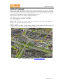
Note:The map is provided by www.chachaba.com .
APPENDIX ︱ 19