1
l
nua
a
m
s
’
User
T910
NAKI88
5
0B
100M
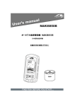
NAKI8850B
ENT
MENU
EXIT
T810
(optional)
www.goyachting.cn
All right reserved! Except as expressly provided herein,
no part of this manual may be copied, reproduced, republished, transmitted or distributed for any purpose, without
prior written consent of Yachting Electronic Co., Ltd.
Yachting Electronic may find it necessary to change or end
our policies, regulations, and special offers at any time.
We reserve the right to change or improve its products and
to make changes in the content without obligation to notify
any person or organization.
For current updates or other information, please visit our
website:
www.goyachting.cn
Yachting Electronic Co., Ltd
Building107, No.508, Heyan Road,
Nanjing, 210038, China
Printed in China
Copyright 2008 Yachting Electronic Co., Ltd.
All rights reserved.
i
Content
Introduction ......................................................................1
Packing list........................................................................2
General attention...............................................................2
Understanding Sonar.........................................................3
Installation.........................................................................5
Installing the battery.....................................................5
Installing the transducer...............................................7
Transom installation..............................................7
(for T810 transducer)
Shoot-thru-hull installation.................................16
(for T810 transducer)
IceEDQN fishing installation..............................21
(for T910 transducer)
Using the transducer......................................22
Ice fishing......................................................23
Boat fishing...................................................25
Operational Panel Basic..................................................27
Display............................................................................28
ii
Understanding the display.........................................28
Depth Range..............................................................29
Water surface line......................................................30
Operation........................................................................32
Menu Operation Instruction......................................32
Sensitivity..................................................................34
Chart Speed...............................................................35
Shallow......................................................................36
Depth Range..............................................................37
Fish ID.......................................................................38
Units..........................................................................39
Backlight...................................................................40
Contrast.....................................................................41
Load DFT..................................................................42
Trouble Shooting............................................................43
Maintenance...................................................................47
Guarantee Conditions.....................................................48
iii
Specfications and Feature...............................................49
Specfications...................................................................49
Features...........................................................................50
Contact us........................................................................51
iv
Introduction
Thank you for choosing our Fish Finder. and welcome
to the innovations of Yachting Electronic Co., Ltd! We has
been committed to fish finder R&D activities all the way
and its products have been reputed for their cutting-edge
technologies and reliable performance.
The unit is designed to facilitate fishing on the bank, along
the seashore,and on-board in a variety of water areas.
We offer one year charge-free main-tenance against any
damages induced by non-human factors; and damages
beyond the six months are handled with reasonable charges
based on concrete situations. For details regarding maintenance service, please refer to the warranty explanations.
To familiarize yourself better with the product’s operation
and maximize the utilization, we invite you to read the
User’s Guide carefully.
For any possible problems you may encounter during the
operation, please switch to the Trouble shooting section
for reference.
1
Packing list
The following items are included in the gift box:
1) A handheld with 3” Dot matrix LCD
2) A transducer with 6m cable
3) A copy of User’s Guide
Note: the standard matched transducer of NAKI8850B is
T910, which can be used with ice/bank fishing. However
there is another T810 transducer can be used in boat fishing,
which is optional for customer.
In the event that any of the items listed is found missing,
call us immediately or log on to our website at
www.goyachting.cn. Clients located in other parts of the
world may also refer to their respective local distributors.
General attention
Warning: Disassembly and maintenance are only to be
Warning
performed by professionals designated by the Company.
Any of the following situations can void the remainder of
your warranty: unauthorized disassembly or maintenance,
damage or alteration to the production serial number, etc.
2
Warning:
ing: Although the unit is designed waterproof, it is
Warn
strongly warned not immerge it into in water, whcih may
cause damage of inner electronic part.
Understanding
Understanding sonar
sonar
If you are familiar with how sonar works, skip ahead to the
next segment. But, if you have never owned sonar Fishfinder
before, this segment will tell you the basic working theory
about sonar.
Based on the sonar technology, the Fishfinder could
detect the underwater
condition, including fish,
structure, or bottom. After
you finished the installation
of transducer and sonar unit,
connect the sonar unit to the
transducer. The transducer
sends a sound wave signal
into the water in a cone shape. At the source, the wave is
narrow; however as it penetrates deeper, the sound wave
spreads forming a cone (think flashlight). The sound wave
bounce back to the transducer when it strikes any object,
the object could be fish, structure, bottom or any other
object with density being different from the water.
The transducer amplifies the return signal and sends it
back to the Fishfinder. By measuring the time between the
transmission of the sound wave and when the sound wave
bounce back, the Fishfinder could calculate the distance by
the inner microprocessor. Then the Fishfinder display the
information on the screen for you to interpret.
Installation
Installing the battery
Warning: do not split the battery cover
with strength in the vertical directiion!
To take off the battery
cover, put and slide it
with some strenth
1. Turn the screw anti-clockwise with a screw driver.
Then slide the Battery Door towards the bottom of the
unit and remove it from the main housing.
2. Install 4 “AAA” batteries. Be certain that the batteries
are aligned as per the diagram within the battery
compartment.
3. Slide the Battery Door towards the top of the unit until
it is completely closed. Then turn the screw clockwise
with a screw driver until snug before continuing. Be
certain not to over-tighten it.
Installing the transducer
Transom
Trans
om installation
installation (for T810 transducer)
1. Select the mounti
mounting
ng location
When you select a mounting location for the transducer,
the flowing should be considered in advance.
The sonar transmission / reception can be affected severely
in turbulent water, so please do not mount transducer behind
strakes, rows of rivet, water intake, discharge port, the
immediate area of the propeller(s). These areas can create
turbulence when the boat moves in a high speed.
Do not mount the transducer in locations where it may be
vibrate severely when the boat’s engine launches or stop.
After the installation is finished, make sure the transducer is
pointed down straightly to the water surface.
2. Mark the location
location and drill the mounting holes
1) Make sure the boat is level and no obvious incline of the
shipboardDŽ
2) Hold the template against the transom of boatˈmark
two mounting holes in the two slots. The center of two
Mark the two position
holes should be parallel
with water surface.
Make sure the distance between
the bottom of template and the
lower edge of the transom
is about 0~5mm.
0~5mm
3) Using a 5/32” bit, drill 2 holes approximate 1” (25mm)
deep at the marked location. Be careful not drilling too
deep then 1”.
3. Assemble
Assemble the transducer
1) Slightly spread the pivot
and match the transducer
to the pivot. The toothed
surface make them not
separating easily.
a)
b)
Note: when match the
transducer and pivot, please be
careful not assembling them reversedly. ( see the figureˈ
a-rightˈb-wrong)
2) Put the locking nut into the slot of pivotˈthen insert the
pivot boltˈhand-tighten the pivot bolt.
NoteDo
not over tighten the pivot-bolt with Allen
Note
wrench otherwise you will not being able to adjust the
angle of transducerDŽ
Locking nut
Pivot
Pivot bolt
3) Match the pivot to the template.
Note: Do not push the pivot into the bracket.
Do not push the
pivot into the
bracket
4. Initial installation of transducer
1) Apply marine sealant to the 4 x 15mm screws and the
two holes on transom. Hold the bracket against transom
againˈslightly tighten the template by two 4 x 15mm
screws.
Note: Do not over tighten, otherwise you will not be able
to adjust the transducerDŽ
2) Adjust the template to make it roughly vertical to the
water surfaceˈthen tighten the two screws with Allen
wrench
3) Press the pivot into the bracket, and then rotate the
transducer to make it parallel with the water surface.
Note: The pivot match the transducer by ratchetsˈand
the increment is12 degree, so in some situations you
may find it impossible to adjust the transducer completely
parallel with the water surface. In this situation a slight
incline (1~5degree) is acceptable.
5. Routing
Routing the cable
cable
According to the different situation of boat, you could
choose to route the transducer through or over the transom
to the sonar unit.
If you choose to route the transducer through the transom
to the sonar unit, please follow the steps bellow:
1) hold one cable clamp at the position approximate 1/4
distance from the top of transom to the transducerˈthen
mark the position with a pencil. Using a 1/8” bit, drill
tow holes approximate 3/8” (10mm) deep.
2) Apply some marine sealant to the hole, and then tighten
the cable clamp with two screws.
3) If more than one cable clamp are needed, repeat
step1ˈ2
The template touchs the transducer
Note
Note˖As
the transducer is adjustableˈmake sure the cable
between the transducer and the first clamp is not tighten.
Enough slack should be remained; otherwise the transducer
cable is easily damaged. To make sure such damage will not
happenˈplease rotate the transducer to the utmost position
before tighten the first cable clamp (see figure-7).
4) When route the transducer cable to the sonar unit, avoid
enwinding the transducer cable with other electrical wires
or some electrical device that may cause interference, as
this will affect the transducer’s transmission / reception
of sonar signal.
5. Test the
the initial installation
installation
To get a better installation of the transducer, we suggest you
testing the initial installation and adjust the transducer
according to the test outcome.
Before the test, please make certain you have finished the
installation of the sonar unit and properly connect the
transducer cable to the sonar unit. Also make sure the distance
between the transducer and bottom is not beyond the depth
capability of your Fishfinder.
1) Power up the sonar unit and see whether there is sonar
information on display. If yes, it means the sonar unit is
properly connected to the transducer. If notˈplease
check the connection between the sonar unit and the
transducer.
2) Firstˈrun your boat at a low speed. See the sonar
information on the screen. If the sonar display comes
out normal, then speed up your boat. Always observe
the sonar display during the course. If signal losing or
abnormal sonar display happens when the boat run at
a certain speedˈnote the speed of your boatDŽ
3) Adjust the transducer in a small scope and run the boat
at the noted speed (step 2). Then observe the sonar display.
If the sonar display is normal, go to the next step. If not,
please adjust the transducer until it comes out normal.
If by any means a normal sonar display can not be
obtained, then it is necessary for you to relocate the
position of the transducer.
7. The final
final installation
installation
1) Make sure the transducer could be completely immersed
into water, and then adjust the location of template on
the transom to make the transducer immersed into water
as low as possible. This will make the transducer’s
transmission / reception being affected by the whirlpool
at the smallest extent when the boat runs at a high speed.
2) As soon as you believe having found the best mounting
location of the transducer, release the pivot from the
template, then mark the third hold with a pencil.
The third hole
3) Using a 5/32” bit, drill a hole appreciated 1” (25mm)
deep at the marked position.
4) Apply some marine sealant in three holes and hold the
template against the transom. After you are certain the
installation is completely in line with the mounting
location which you got at step 4, then tighten the three
screws with Allen wrenchDŽ
5) Press the pivot into the template.
Shoot-thru-hull installation (for T810 transducer)
Transom installation is the most widely used method to
install the transducer. However in some situation you also
could use Shoot-thru-hull transducer installation. Which,
compared with Transom installation, is more convenient
and fast. However, considering of the material of boat and
any possible trapped air bubbles in the material, sonar
signals will be slightly reduced when passing through the
boat hull.
1. Preparati
Preparation
on
The boat hull should be single layer construction, since the
sonar signal could not pass through air.
Note: The areas being chosen to mount the transducer
should be free from turbulent water. Any ribsǃstrakes
and other protrusions that may create turbulence should
be avoided.
With double-hulled boat, you could make the shoot-thruhull installation only when some flotation materials (such
as plywood, balsa, wood or foam) are removed from the
chosen area(see the following figure).
Resin
Inner hull
Flotation material
Epoxy
Outer hull
Warning: contact your boat dealers to get the full specifications of your boat. And never try to remove any materials
from the inner hull before you completely know about the
composition of your hull.
Chose an appropriate position in the inner hull, then removing the inner layer of fiberglass and flotation materials,
thus the surface of outer hull exposed.
Epoxy the transducer to the outer layer of fiberglass; press
the transducer with a slight twisting motion to purge any
trapped air from underneath.
After the epoxy cures for 24hours and be certain that the
epoxy is solidified, fill the remaining space with resin. And
then the installation of transducer is finished.
With the shoot-thru-hull installation, the transducer will
not be able to adjust as soon as it is fixed. So, test before
final installation is necessary.
2. Find a better mountin
mountingg location
1) Fill the hull with enough water to submerge the
transducer.
2) In the sump of the boat, place the transducer at the
identified mounting position, face down. To make the
transducer in position, some heavy object could be used.
3) Turn on the sonar unit, run the boat to water area that
the depth is about 20feet to test whether the sonar display
is normal (if needed, please adjust the sensitivity and
depth range). If not, check the connection between the
control head and the transducer.
4) Run the boat at various speed to see the sonar display,
if such phenomena appears: sonar strength obviously
decreasing, signal losing, bottom missing, then note the
speed and choose another location for the transducer.
5) Repeat step 4 until you get the best mounting location
for the transducer.
3. The Permane
Permanent
nt Shoot-Thru-Hull
Shoot-Thru-Hull installation
1) make sure the surface of the chosen location is clearǃ
dry and free of any oil, then sand the mounting surface
of transducer with 100 grit sandpaper until it looks very
clean and flat.
2) Wipe off the sand debris on mounting surface with a
piece of cloth, and then clean the mounting surface of
hull and transducer with rubbing alcohol.
3) Get a quantity of epoxy and hardener, mix them in a
certain proportion and thoroughly, slowly stir them on a
paper plate. Avoid forming air bubbles in the epoxy.
4) When the epoxy looks unworkable (about 20minietes
are needed from the beginning you mixing them), make
sure there are no air bubbles in the epoxy layer, then
spread a thin layer of epoxy on the surface of transducer,
a comparably thick layer to the surface of sand area on
the hull.
5) Press the transducer into the epoxy of the sanding area
on the hull with a slight twisting motion, forcing any air
bubbles out from underneath. Make sure the face of the
transducer will be parallel with the hull after you finish
all the above job.
Warning: do not bump the transducer while the epoxy is
wet. It will take about 24hous for the epoxy curing
completely.
Note: weight the transducer with some heavy object to
prevent it from moving during the epoxy curing. When
the epoxy cures completely, drain out the remained
water from the hull.
6) Route the cable to the control head, and now it’s ready
to use.
Ice / bank fishing installation (for T910 transducer)
Adjusting
Adjust
ing the float
float
ā
)ORDW
7UDQVGXFHU
It is very important to adjust the location of the transducer
under the water. The transducer must be adjusted so that
it is a minimum of 150 mm away from the float. In calm
water the transducer can be set at which will provide the
maximum amount of sonar coverage. In rougher water,
the transducer may need to be lowered into the water
further to provide stabilized readings.
1. Pull out the rubber stopper.
2. Adjust the float so that it is 150 to 250 mm away from
the transducer.
3. Replace the rubber stopper. To prevent accidental loss
of the stopper, always press the rubber stopper firmly
into the float before tossing the transducer into the water.
Using the transducer
1. Toss the sensor and float assembly into the water. To
toss, place the sonar sensor and float in your hand, and
pitch underhand. Do not throw the sensor by the cable
as this will cause unrepairable damage. Before tossing,
be certain that the cable is free from tangles and is not
wrapped around anything.
2. Use a pole to guide the sonar sensor to a desirable
position or add floats on the cable to put the sensor at
the corresponding position.
3. To retrieve the sensor and float simply pull in the cable
being certain to neatly wind up the excess cable.
Note: To remove the Sonar Sensor Float, remove the
rubber stopper first, then slide the cable through the center
of the float toward the plug and gently work the plug
through the center of the float in a rocking motion. To add,
reverse the steps above.
Warning: Do not allow the cable to sink to the bottom as
it may become entangled in debris.
Ice fishing
It is usually difficult to find the appropriate fishing position
when doing ice fishing, yet this product (NAKI8850B) will
make things easy. To achieve the best performance for ice
fishing, it is highly recommended that you cut a hole
through the ice and place the Fish Finder directly in the
water. However, by using NAKI8850B, you don’t have to
cut holes again and again to find the suitable fishing position.
Please follow these steps when doing ice fishing:
Spray water on the ice
Note: To use ice fishing,
you should choose T820
transducer.
1. Find an appropriate position on the ice surface. Clear
away snow to expose the ice surface, making sure the
surface is smooth.
2. Spray a small amount of liquid water on the ice and set
the sensor on the water allowing the unit to freeze to the
ice.
3. If there are any air pockets between the sensor and ice,
the unit will not work properly, and will require you to
try another spot, or cut a hole in the ice to put the sensor
directly into the water.
4. To remove the sensor from the frozen ice, gently tap the
sensor at the base with your hand. If it will not come
loose, spray a small amount of water on the ice surface
around the base and repeat step 4 until the sonar sensor
is easily removed.
Note: Due to various environmental conditions, the above
process may be a little different in some situations.
Warning: Never use a blunt object to strike the sonar
sensor as this may cause damage to the sensitive internal
electronics.
Boat fishing
There are three ways of using the Fish Finder from a boat:
1. Toss the sensor into the water as said in the previous
instructions.
2. “Shoot-Thru” the hull of a boat:
coat the hull face below of the sensor with Vaseline and
press it against the hull bottom with a twisting motion.
Vaseline
If depth readings appear as “---” while using the “thootthru”, place the sensor directly in the water to verify that
the Fish Finder is operating properly. If it operates properly
while directly in the water, reposition the sensor in a new
location in the hull, and repeat methods A, B, or C. These
methods do not work on all hulls and you may have to
place the sensor directly in the water for proper operation.
Note: T he “shoot thru” capability of the Fish Finder does
not apply to all boats. The hull must be made out of solid
fiberglass, or a maximum of 3 mm aluminum, and be in
direct contact with the water, with no air pockets.
Operational Panel Basic
(1) Transducer plug
(2) Depth Reading
(3) Water surface line
(4) Temperature Reading
(5) Fish Icon
(6) Bottom
(7) Depth Range
(8) Sensitivity Reading
(9) Battery Strength
(10) Power Key
(11) Ent Key
(12) Menu and Exit Key
(13) Down Arrow Key.
(14) Up Arrow Key
Display
1. Understanding
Understanding the
the display
Water surface
line
Depth reading
Temperature
reading
Sonar information
scroll from right to
left
Fish icon
Bottom
Sensitivity
Depth range
Battery strength
(1) Depth reading: indicate water depth
(2) Temperature reading: indicate atmosphere temperature
(3) Sensitivity: the curren sensitivity setting
(4) Water surface line: display the position of water surface
(5) Fish icon: a fish symbol to display the detected target
(6) Bottom: indicate the bottom condition
(7) Depth range: the current Depth range setting
(8) Battery strength: indicate the remained battery strength
The detection graph is shown from the right corner from
top to down. It would scroll forwards to left continuously.
The most present and newest signals are displayed on the
rightmost screen. And the leftmost are those of 16 seconds
ago.
2. Depth
Depth range
rang
The unit will automatically adjust the depth range according
to water conditions. It always keeps the bottom displayed
in the lower portion of the screen.
When the depth unit is set to feet, this fish finder has the
following depth ranges: 15, 30, 50, 65, 130, 200, 260
and feet.
When the depth unit is set to meter, the fish finder has the
following depth ranges: 5, 10, 15, 20, 40, 60, 80, and 100m.
Depth range changes or signal loss will cause lines with
missing detail and / or abrupt changes in the graphed bottom.
The screen image jump shown here is due to an automatic
change in depth.
New returns graphed at a different scale will not match up
with the historic data already graphed at a higher or lower
scale.
3. Water surface line
The water surface line indicate the displayed position of
water surface on the screen, which is very helpful for you
to estimate the depth of
detected fish.
For example,
the current depth reading
is 18m, and the position
of fish icon(B) is about
1/3 of total depth( A), thus
the fish-a lies on the position
about (18.6*1/3=)6.2m deep
from water surface.
Accordingly, you could estimate the fish-b lie about 1/2 of
the A total depth, which is (18.6*1/2=)9.3m.
Underwater conditions vary greatly, so some experience is
needed to get the most benefits of your fishfinder. Use the
message displayed in the screen as a helpful tools for your
judgment, thus you could exert the full function of your
fishfinder.
Operation
Menu O
Operation
peration Instruction
Instruction
The menu setting of NAKI8850B is convenient and friendly.
You can get various function setting by simple operation.
1) Power key: Power on / Power off
Note: to shut off the unit, press the Power key and keep it
for 3s, then release it.
2) ENT key: To confirm a setting / hold the screen.
Note: when the unit is
working, pressing Ent key will
“freeze” the screen, which is
helpful for you to carefully
study the underwater condition.
Note: when you enter into a menu setting, pressing Ent
key, then you are able to change the setting and the frame
line of current menu will look thicker then non-setting. see
following:
thicker
non-setting
setting
To exit the setting condition, press ENT key again.
3) MENU & EXIT key: to enter or exit menu setting.
4) Up arrow / down arrow key: to increase / decrease the
setting value.
Sensitivity
Sensitivity determines how echoes will be displayed on the
screen.
Increasing the sensitivity will make you see more details
on the screen. In such situations when you see too much
clutter on the screen, decreasing the sensitivity will play
an effect. The larger the sensitivity is, the more relatively
strong sonar returns the screen will display. If the sensitivity
is decreased too low, most sonar returns (which maybe fish)
will not be displayed.
In situation while water is clear or very
deep, try increasing the sensitivity,
which will let you see even the very
weak returns.
However in situation while water is
turbid, try decreasing the sensitivity,
which will make only the useful echo
be showed on the screen and the noise will be omitted.
To set the Sensitivity:
1) Press MENU to enter into menu setting,
2) Use the Up / Down Arrow to select Sensitivity option.
3) Press ENT to confirm selecting
4) Use the Up / Down Arrow to increase / decrease the
value
5) Press ENT to confirm the setting.
6) Press EXIT to exit.
Chart speed
Chart Speed control how fast the sonar information moves
across the screen.
With the high speed, you could see more information across
the screen; however the fast moving information makes
you feel difficult to interpret the
fish details and bottom.
With the low speed, you fell easeful
to have enough time to interpret the
fish details and bottom. However the
compressed information may cause
a little problem for you to interpret
them.
35
To achieve better images, try adjusting the Chart Speed
level to match the actual condition: stationary, drifting
slowly or running you boat at different speed.
To set the Chart Speed:
1) Press MENU to enter into menu setting,
2) Use the Up / Down Arrow to select Chart Speed option.
3) Press ENT to confirm selecting
4) Use the Up / Down Arrow to
5) Press ENT to confirm the setting.
6) Press EXIT to exit.
Shallow
Shallo
The Fishfinder sound an alarm tone
when the bottom goes shallower or
equal than the alarm’s setting.
You also could exit alarm mode by
enter into Shallow menu and
artificially increase the current
depth alarm value to a safe grade.
36
To set the Shallow:
1) Press MENU to enter into menu setting,
2) Use the Up / Down Arrow to select Shallow option.
3) Press ENT to confirm selecting
4) Use the Up / Down Arrow to increase / decrease the value
5) Press ENT to confirm the setting.
6) Press EXIT to exit.
Depthh Range
Dept
Range
Depth Range determine in which portion the bottom will
display in the screen. (For example, if the actual depth is
10m, and the current Depth Range is 20m, then the bottom
will display on 50% portion of the screen).
To set the Depth Range:
1) Press MENU to enter into menu
setting,
2) Use the Up / Down Arrow to
select Depth Range option.
3) Press ENT to confirm selecting
4) Use the Up / Down Arrow to
change the value
37
5) Press ENT to confirm the setting.
6) Press EXIT to exit.
Fishh ID.
ID.
Fis
Fish ID control the way the detected target is displayed on
the screen.
1) If Fish ID is on, a fish icon will be displayed when some
fish and other object is detected.
2) If Fish ID is off, a arch will be displayed on the screen.
Fish ID is On
Fish ID is Off
Note: your sonar unit is advanced, however it can not
distinguish between fish and other suspended objects such
as turtles, trotlines, submerged floats, air bubbles, etc. One
word, it could be fooled. So, you may see fish icon on the
screen, actually there is no fish underwater.
However, the Fish ID is very helpful for you to take some
of the work out of studying the screen. That means Fish ID
provides you a tool to distinguish the fish in a max possbility
38
and omits other negligible sonar information.
To know as more as possible what’s under your boat, we
suggest you turn off the Fish ID, and only study the sonar
returns which is displayed as archs.
To set the Fish ID.:
1) Press MENU to enter into menu
setting,
2) Use the Up / Down Arrow to
select Fish ID.. option.
3) Press ENT to confirm selecting
4) Use the Up / Down Arrow to
change the value.
5) Press ENT to confirm the setting.
6) Press EXIT to exit.
Units
Units is used to choose depth unit and Temp unit. There
are four combinations for you to choose the depth unit and
Temp unit:
Fahrenheit / Feet
Fahrenheit / Meter
39
Celsius / Feet
Celsius / Meter
To set the Units..:
1) Press MENU to enter into menu
setting,
2) Use the Up / Down Arrow to
select Units. option.
3) Press ENT to confirm selecting
4) Use the Up / Down Arrow to
change the value.
5) Press ENT to confirm the setting.
6) Press EXIT to exit.
Backligh
Backlight
Backlight is used to let you choose
whether the backlight is on or auto
in some enviroment.
To set the Backlight:
1) Press MENU to enter into menu
setting,
2) Use the Up / Down Arrow to
40
select Backlight. option.
3) Press ENT to confirm selecting
4) Use the Up / Down Arrow to change the value.
5) Press ENT to confirm the setting.
6) Press EXIT to exit.
Contrast
Contrast is used to let you get a most suitable display when
you operate the unit.
To set the Contrast:
1) Press MENU to enter into menu
setting,
2) Use the Up / Down Arrow to
select Contrast option.
3) Press ENT to confirm selecting
4) Use the Up / Down Arrow to
increase / decrease the value.
5) Press ENT to confirm the setting.
6) Press EXIT to exit.
41
Loadd DFT
DFT
Loa
Load DFT is used to restore to the factory settings.
To set the Load DFT:
1) Press MENU to enter into menu
setting,
2) Use the Up / Down Arrow to
select Load DFT option.
3) Press ENT to confirm selecting
4) Use the Up / Down Arrow to
change the option.
5) Press ENT to confirm the setting.
6) Press EXIT to exit.
42
Trouble shooting
1. Nothing Ha
Happens
ppens When I turn the Power On.
a) Make sure that you have installed a good set of
batteries and aligned them as per the diagram within
the battery compartment.
b) Make sure that the temperature of the environment is
above -10~45degree. When using this product in the cold
environment, please make sure that the temperature of
the main unit is above certain degree.
2. Weak Bottom Ech
Echo,
o, Unstable Depth Reading, or No
Fish Signals.
a) Make certain the transducer is installed properly.
b) Extremely heavy vegetation may confuse the sonar
signal, causing it to misinterpret the depth. If you are
certain that the readings are incorrect under these
conditions, discontinue use.
c) Oil, dirt and fuel might cause a film to form on the
transducer and reduce its effectiveness. Cleaning the
43
face of the sensor might help.
d) Electrical noise from the boat's motor can interferes
with the sonar, which will cause some weaker signals
being eliminated.
e) Please check the battery voltage. The unit's transmitter
power will decrease due to the voltage drop. And this
will reduce its ability to find the bottom or targets.
f) The sonar might be in turbulent water. Mounting it in
a smooth flow of water might help.
3. No depth reado
readout
ut when transducer is installed in the
way “Shoot-thru-hull”.
Make certain the hull of the boat is single layer construction.
Also any air trapped in the lamination of the fiberglass
would prevent the sonar signal passing through, which will
cause no depth readout.
4. Bottom disappe
disappears,
ars, suddenly weakens, when the boat
moves at high speed
a) The sonar might be in turbulent water. See the installation guide and adjust the transducer position to a
44
smooth flow of water.
b) Electrical noise from the boat's motor can interferes
with the sonar, which will cause some weaker signals
being eliminated. Try increasing the Noise Reject level
or routing Fishfinder”s power and the transducer cable
away from the electrical source.
appears
ars on the display even you can see fish
5. Nothing appe
under the transducer.
a) Check the transducer installation to make certain it is
properly installed. An improper installation may cause
sonar signal lost.
b) Oil, dirt and fuel might cause a film to form on the
transducer and reduce its effectiveness. Cleaning the
surface of the transducer might help.
c) Electrical noise from the boat's motor can interferes
with the sonar, which will cause some weaker signals
being eliminated.
6. The display beco
become
me so cluttered that you even could
not achieve a clear bottom
45
Such cluttered display maybe caused because:
a) The water is too low
b) The water is too turbid
c) There are so much debris in the water
46
Maintenance
With a view to making most of your Fishfinder, we recommend you follow the steps bellow and carry out maintenance.
1. For the case
Cleaning the sonar unit’s outer case (except for the screen)
with a cloth dipped mild detergent solution, and then wipes
it dry.
2. For
For the screen
Use a piece of soft cloth or pelt to clean the screen (fresh
water or eyeglass cleaner can be used if needed). Stubborn
dirt or oil stains remaining on the screen shall not be wiped
with force; otherwise it may scratch the surface.
Additionally, give daily attention to ensure the screen is
keep of any chemicals.
3. Storage
Never place your Fishfinder in an enclosed compartment
of the vehicle! High temperature building up due to
47
concentrated air in hot days can pose damage to internal
electronic parts.
Guarantee Conditions
1. We assure you this product is free from defects in materials
and workmanship. The warranty coverage is One Year from
the date of purchase, during which if the unit fails to perform
as described in the product’s written specifications, we will
repair or replace it free of charge. As for products exceeding
the warranty coverage, the maintenance department will
charge customers some fees according to the real situation.
2. This warranty is void if damage or malfunction is due
to abuse, misuse, accident, failure to reasonably maintain,
improper installation or use, or unauthorized alteration or
repairs. Our company retains the final right to judge or
repair the defected products.
3. Our company holds the right to update the products.
And it is not obligated for our company to update the former
products according to the new standard.
48
Specifications and feature
1. Specifications:
1) Display
Display: 3.0in / 76mm, FSTN LCD
Display Resolution: 128 x 64 (H ×W) Pixels
Display Contrast: 0~100% Adjustable Range
Backlight: On / Auto
Visible in strong sunlight
2) Sonar
Depth Capability: 100m
Sonar Frequency: 190KHZ
Sonar Beam Angle: 45°
Sonar Alarms: Fish / Shallow
3) Technical And Casing
Back-Up Memory: Built-in memory stores sonar settings
when the unit is turned off.
Operational Temperature: From -10C to 50C (14 Fto122 F)
Sensor Cable Length: 6 M (20 Feet)
Unit Dimensions: 138mm × 69mm × 32mm.
49
IPX7 Level Sealed and waterproof casing design
4) Power
Power Supply: 4 × AAA Alkaline Batteries
Handheld Battery Life: 20 Hours Continuous Use
Handheld Power Off Automatically In 10 Minutes Without
Any Using.
2. Features
1) Switchable Fish Identification mode
2) Sensitivity: 0~100% Adjustable Range
3) Chart Speed: 0~100% Adjustable Range
4) Multi level Depth Range
5) “Freeze” Screen At Any Time
6) Depth Units: Meters / Feet.
7) Temperature Units: Celsius / Fahrenheit
8) Fresh / Salt Water Environment
9) True Changing Water Bottom Graph.
10) Big / Small Fish Identification
50
Contact Us
Contact Our Resource Center in any of
the following days:
By telephone:
Monday - Friday: 8.am. to 5:30 pm.
(Central Standard Time)
0086 25 84680809
Or by e-mail:
Typically we respond to you in 2 business days
[email protected]
For direct shipping, our address is:
No.508, Heyan Road,
Nanjing, 210038, China
Yachting Electronic Co., Ltd
51
www.goyachting.cn