1
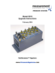
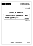
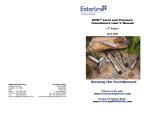
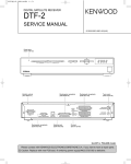
8401
User’s Manual
July 2000
www.PressureSystems.com
Our Publication Disclaimer
This document is thoroughly edited and is believed to be thoroughly reliable. Pressure Systems assumes no liability for
inaccuracies. All computer programs supplied with your products are written and tested on available systems at the
factory. Pressure Systems assumes no responsibility for other computers, languages, or operating systems. Pressure
Systems reserves the right to change the specifications without notice.
Our Company
Pressure Systems develops, manufactures, and services level and pressure measuring instruments where the highest
level of traceable accuracy is required for aerospace, industrial, municipal, and environmental applications. Our products
have become the world standard for electronic level and pressure measurement and scanning. We are committed to the
highest quality design, manufacture, and support of level and pressure instrumentation that is in the best interest of our
customers. Pressure Systems is an ISO9001:2000 certified company.
Our Warranty
Pressure Systems warrants this ESP Pressure Scanner product to be free of defects in material and workmanship under
normal use and service for one (1) year from date of shipment.
Merchandise Return Procedures
If your system seems to be in good working order, but the data seem abnormal, contact the Applications Support Group
at Pressure Systems. The staff is available for troubleshooting at (757) 865-1243 or toll free at 1-800-678-7226 (SCAN)
during normal working hours, Eastern time. If the entire system or any part must be returned to Pressure Systems, please
obtain a Returned Merchandise Authorization (RMA) from the Customer Service Department.
Be prepared to supply the following information when requesting the RMA:
!
!
!
!
!
!
Part number
Serial number
Complete description of problems/symptoms
Bill To and Ship To address
Evaluation/repair purchase order number (not required for warranty repairs)
Customer contact and telephone number
The above information, including the RMA number must be on the customer=s shipping documents that accompany the
equipment to be repaired. Pressure Systems also requests that the outside of the shipping container be labeled with the
RMA number to assist in tracking the repairs. All equipment should be sent to the following address:
ATTN: CUSTOMER SERVICE (7-digit RMA number)
Pressure Systems, Inc.
34 Research Drive
Hampton, Virginia 23666
Pressure Systems will return North American warranty items prepaid via UPS GROUND. Overseas warranty items will be
returned via AIR FREIGHT. If the customer desires another method of return shipment, Pressure Systems will prepay
and add the shipping charges to the repair bill.
Incoming freight charges are the customer=s responsibility. The customer is also responsible for paying shipping charges
to and from the Pressure Systems factory for any equipment not under warranty.
All products covered under warranty policy will be repaired at no charge. An analysis fee will be charged to quote the cost
of repairing any item not under warranty. If, for any reason, the customer decides not to have the item repaired, the
analysis fee will still be charged. If the quote is approved by the customer, the analysis fee will be waived. The quote for
repair will be based on the factory=s flat rate for repair, calibration, and board replacement. When these prices do not
apply, the quote will be based on an hourly labor rate plus parts. All replaced parts are warranted for 90 days from the
date of shipment. The 90-day warranty is strictly limited to parts replaced during the repair.
Pressure Systems, Inc.
8491 User’s Manual
Theory of Operation
Introduction
Remote pressure sensing inherently involves a separation of data sensing elements and data
collection equipment. Correct operation of the remote equipment is essential to overall system
performance. Ensuring that proper power is supplied to the sensing equipment is a major
concern. It is possible to supply excess power and regulate it at the sensing equipment.
However, this imposes thermal loads and cabling requirements that can be detrimental to
operation of the sensing equipment and to the systems under test. The 8491 SDI Remote
Power Supply fills the need to supply regulated power at the remote sensing equipment with
reasonably sized cables of useable lengths.
System Description
There are currently four-wire remote sensing power supplies available and commonly used to
ensure proper voltage is available at the load. However, most commercial power supplies can
only handle supply line impedance drops of one-half volt. This places severe restrictions on
wire size, cable length, and current capacity. For example, with supply line impedance drops of
one-half a volt, cable for a two amp, 12 volt supply could not exceed one- quarter ohm (¼ Ω) or
approximately 23 feet of 20 AWG cable.
The 8491 SDI Remote Power Supply uses remote sensing to provide sufficient operating
voltages to the System 8400 SDI. Depending on loads, the 8491 SDI Remote Power Supply
will accommodate six ohms (6Ω) of supply line impedance. For example, this will allow a fully
populated SDI (an SDI with sixteen ESP scanners) to operate at the end of a 22 AWG cable
over 340 feet long. Alternately, cables of mixed wire sizes can be used in order to maximize the
flexibility of portions of the cable (e.g., 270 feet of 22 AWG with 30 feet of 26 AWG for a 300 foot
total length).
The 8491 SDI Remote Power Supply is a 19 inch rack-mountable instrument that can be
configured to operate on either 115 VAC or 230 VAC, 50/60 Hz. (Input voltage may be changed
by merely reversing the fuse insert in the power entry module and connecting the appropriate
line cord. (See Section 2.2, Installation.) The case is fully enclosed and the unit may also be
used outside a rack. The 8491 SDI Remote Power Supply contains four independent, isolated,
power supplies with individual remote sensing.
Front panel features aid installation and setup as well as providing monitoring capabilities. (See
picture, next page.) The front panel contains four analog current meters, four separate circuit
breakers, a power switch and a digital voltage meter with a four-position selector switch. The
output current of each power supply can be continuously monitored via the analog meters. The
output voltage of any of the four supplies can be checked with the digital panel meter by
selecting the desired output with the four-position selector switch. Each output is protected by a
circuit breaker. The circuit breakers are reset from the front panel.
Page 1
www.PressureSystems.com
Pressure Systems, Inc.
8491 User’s Manual
Figure 2.1
Remote Power Supply Front Panel
The power switch disconnects the unit from the power mains and is illuminated whenever
power is applied.
The rear panel of the 8491 Remote Power Supply contains the IEC power entry module and
two (2) output connectors.
WARNING: The two output connectors may NOT be used simultaneously!
The 15-pin D-sub-miniature connector matches the power connector on the System 8400 SDI,
allowing fully reversible one-to-one cables to be used. The 15-pin circular connector is provided
for installations desiring a more physically robust back panel connector. A blocking plate is
attached, covering one of the two connectors. This plate must be moved to switch to the type of
output connector desired. Slots are provided so that the plate can be moved without its having
to be detached. Simultaneous use of both output connectors will force incorrect voltages into
attached equipment with the potential for catastrophic equipment damage. (See warning
above.)
A significant portion of the rear panel is covered with cooling air vents. Airflow is into the top of
the unit through two (2) filtered cooling fans. Air exits through the vents in the rear panel. A
minimum clearance of 1.5 inches is required over the fan filters and behind the rear panel exit
vents.
Page 2
www.PressureSystems.com
Pressure Systems, Inc.
Figure 2.2
Remote Power Supply Rear Panel
8491 User’s Manual
Figure 2.3
D-Shell Connector
Installation
The 8491 SDI Remote Power Supply may be operated from a bench top or installed in a 19
inch rack. The 8491 SDI Remote Power Supply is heavy (19.1 kg) and when installed in a
rack, all four panel bolts must be in place and threads on the attaching bolts must be fully
engaged.
Input: Two models of the 8491 SDI Remote Power Supply are available to accommodate
international voltages. The following paragraphs describe how the standard model may be
configured to accommodate 110 VAC to 240 VAC. The 100 VAC model does not have this
configuration capability. If your unit is a 100 VAC model, simply connect your IEC line cord
between the unit and your 100 VAC power lines and proceed to the paragraph marked “Output”
in this section.
A standard IEC line cord (supplied) connects the unit to the power mains. The IEC power entry
module’s fuse block is used to configure the operating voltage of the unit as either 115 VAC or
230 VAC. Ensure the correct voltage setting is visible in the window of the power entry module
before applying power to the unit. If incorrect voltage is displayed, or if fuses need to be
installed, follow the procedure below.
To install, replace, or check the fuses in the unit or to change the voltage setting of the unit:
The line cord must be removed from the IEC connector before attempting to open the cover.
1.
Open the fuse cover of the power entry module (located on the rear panel of the
8491 SDI Remote Power Supply and extract the red fuse holder. To accomplish this, pry open
the fuse cover using a small slotted-head screw driver. Insert the screwdriver into the notch on
the end of the power entry module near the voltage window. (See pictures.)
Page 3
www.PressureSystems.com
Pressure Systems, Inc.
8491 User’s Manual
Figure 2.3
Preparing to Open the Fuse Cover
Figure 2.4
Remove Fuse Block
2.
Remove red fuse block from the power entry module. Fuses of the same
amperage are placed in both sides of the red fuse block. Note that the fuse block is marked
with 115V and 230V, and can be inserted in two orientations. Choose the orientation where the
appropriate voltage will be visible through the window on the cover when the cover is closed.
Page 4
www.PressureSystems.com
Pressure Systems, Inc.
8491 User’s Manual
Figure 2.5
Fuse Block Orientation
3.
Reinsert the red fuse block into the power entry module. Once the fuse block is in place
and the cover snap-closed, the line cord may be reinstalled and the unit is then
ready to accept appropriate input power. (NOTE: 3 amp fuses are used with 120
VAC units and 1.5 amp fuses are used with 230 VAC units. See Appendix A,
Specifications.)
Output:
The output power cable connects the 8491 SDI Remote Power Supply to the
SDI. Sense line connections are internal to the SDI. With this cable and the line cord connected,
the unit is ready to operate. Push the power switch to latch it and the unit is ON. Currents can
be monitored on the front panel meters. The supply can safely operate with no load. An SDI
with no scanners will draw approximately 0.9 amps on the 5 volt digital supply. Output voltages
can be monitored by depressing the voltage selection switch corresponding to the voltage to be
monitored. External voltage measurements must be done at the load. Non-SDI loads (i.e. test
or calibration loads) must supply the sense line connections internal to the SDI (See Appendix
C, Test Load).
Calibration
The 8491 Remote Power Supply comes preset from the factory, and in normal use should not
require any field adjustments. Identical post regulator boards are used for each supply and are
interchangeable. Adjustment is normally not required if a post regulator board previously
calibrated for one voltage is exchanged for a board in a matching voltage range (i.e., a ±12 volt
to a ±12 volt position or a 5 volt to a 5 volt position). However, if the post regulator boards are
moved from one voltage range to another, the output will require adjustment.
There are two adjustment potentiometers on each post regulator board. R11 adjusts the output
voltage, while R8 affects the load regulation. User adjustment of the R8 potentiometer is
normally not required and is not recommended. R8 is sealed at the factory.
Page 5
www.PressureSystems.com
Pressure Systems, Inc.
8491 User’s Manual
Figure 2.6
Adjustment of Potentiometers
The output voltage may be adjusted with the following procedure; however, the unit must be
opened to perform make the adjustment. This is NOT considered a part of normal operations.
The procedure must be performed by a qualified technician, familiar with power supply
maintenance and the safety procedures associated with working on open electrical equipment.
Tools required; Phillips-head and small slotted-head screwdrivers.
1.
Remove the four (4) Phillips-head screws in the front panel and gently pull the panel
forward, being careful not to disconnect any of the connecting wires.
2.
The post regulator sub-rack is now accessible with the ends of the four post regulator
boards isible. The voltage adjustment potentiometer (R11) is positioned midway up each post
regulator board. It is mounted at a right angle to the printed circuit board (PCB) and is directly
accessible from the front of the unit. Matching the front panel markings, from left to right, the
post regulators control the +12 volts, the -12 volts, the 5 volt logic supply, and the 5 volt
excitation supply. Locate the appropriate PCB and associated R11 for the output voltage
requiring adjustment. (See picture, below.)
3.
The voltage supply may be monitored by using the front panel voltage selector switch
(four-position switch) and the front panel digital voltage meter. Some manipulation of the front
panel or the use of a mirror may be required to view the meter. Alternatively, an external meter
may be used. An appropriate load with proper sense line connections must be in place. (Use
normal operating load or see Appendix C.) Any external meter must be connected at the load.
With a slotted-head screwdriver, adjust the R11 corresponding to the supply being monitored,
setting the delivered voltage. R11 should provide a minimum adjustment range of ±5% from
nominal.
4.
Other post regulators may be adjusted in a similar manner.
5.
Replace the front panel, taking care not to pinch any of the cables. Re-install the four (4)
Phillips-head screws and the procedure is complete.
Page 6
www.PressureSystems.com
Pressure Systems, Inc.
8491 User’s Manual
Troubleshooting
The 8491 SDI Remote Power Supply is a robust, multiple output, linear power supply.
Operation of the unit is essentially trouble-free.
Most problems that arise will be due to poor or incorrect connections. Ensure the sense lines
are properly connected to the correct delivered voltages at the load and that the connections are
contiguous back into the unit. The high-density 15-pin connectors are reliable when properly
installed and secured, but can be damaged during improper handling. The connectors should
never be probed! Probing the connectors with wires or test leads will damage the sockets and
degrade their current-carrying capability. This may cause intermittent connections or prevent
them from making any contact.
Check for bent, broken, missing, or recessed pins. Crushed or damaged cables are also a
source of problems with remote sensing equipment. Look for damage near the connectors,
where the cable passes through a bulkhead or anywhere the cable may be exposed to traffic.
The cables and connectors should be repaired or replaced as necessary. (See Appendix B
and C, Cable Design, for correct cable wiring diagram.) If the problem persists, contact
Pressure Systems, Inc., for assistance. (1-800-678-SCAN).
Page 7
www.PressureSystems.com
Pressure Systems, Inc.
8491 User’s Manual
Appendix A
Input:
Standard Model:
Maximum Input Power:
Specifications
120 VAC configuration:
120 VAC ±10%, 50/60 Hz with a 3 amp time delay fuse
(3AG)
230 configuration:
230 VAC ± 10%, 50/60 Hz with a 1.5 amp time delay fuse
(3 AG)
100 VAC Model:
100 VAC ± 10%, 50/60 Hz with a 3 amp time delay fuse
(3 AG)
340 watts
Maximum Regulated Output Current:
+12: 2 amps at +12 volts ±5%
- 12: .75 amps at -12 volts ±5%
Vd: 1.5 amps at +5 volts ±5%
Ve: 1.5 amps at +5 volts ±5%
Environmental:
Operating temperature range:
0 to 500C
Humidity:
0 to 95% relative humidity (non-condensing)
Pressure:
1 atmosphere (+5% -15%)
Weight:
19.1 kg (42 pounds)
Dimensions:
19" rack-mountable; 5U high space required
External dimensions:
19" wide (483.0 mm)
6.97" high (177.0 mm)
17.11" deep (434.5 mm)
Remote Power SupplyTop View
Page 8
www.PressureSystems.com
Pressure Systems, Inc.
8491 User’s Manual
Remote Power Supply
Front View
Page 9
www.PressureSystems.com
Pressure Systems, Inc.
Appendix B
8491 User’s Manual
Cable Design
The SDI Remote Power Supply cable consists of virtually any cable length presenting 6 ohms
or less on any leg of seven (7) twisted pair wire, terminated at each end with a male three row
15-pin D-subminiature connector with a pin current rating of at least 2 amps. The connector
must be wired in accordance with the above diagram and Table 1 (next page). Wire length and
size are governed by the overall path resistance. Overall single signal path wire resistance
between the SDI and the SDI Remote Power Supply must be 6 ohms or less.
Page 10
www.PressureSystems.com
Pressure Systems, Inc.
8491 User’s Manual
Table B-1
Cable Wiring
Page 11
TWISTED PAIR
PIN #
ID
NAME
A
2
-12Vs
-12 volt supply sense
A
11
+12Vs
+12 volt supply sense
B
7
-12V
-12 volt supply
B
5
-12Vrtn
-12 volt return
C
6
+12V
+12 volt supply
C
15
+12Vrtn
+12 volt return
D
4
+5Ves
+5 volt excitation sense
D
14
Esrtn
excitation sense return
E
13
+5Vds
+5 volt digital sense
E
-
NU
F
3
+5Ve
F
9
+5Vertn
G
8
+5Vd
+5 volt digital supply
G
10
+5Vdrtn
+5 volt digital return
1
NU
Not used, no connection
12
NU
Not used, no connection
Not used, no connection
+5 volt excitation
+5 volt excitation return
www.PressureSystems.com
Pressure Systems, Inc.
8491 User’s Manual
Table B-2
Pins to Twisted Pair
Page 12
Connector 1 Pin #
Run
Connector 2 Pin #
1
-none-
1
2
A1
2
3
F1
3
4
D1
4
5
B2
5
6
C1
6
7
B1
7
8
G1
8
9
F2
9
10
G2
10
11
A2
11
12
-none-
12
13
E1
13
14
D2
14
15
C2
15
No connection
E2
No connection
www.PressureSystems.com
Pressure Systems, Inc.
Appendix C
8491 User’s Manual
Cable Design
(Alternate Power Supply)
The SDI Remote Power Supply cable consists of any cable length between 20 feet and 300
feet, nominally of 22AWG, 7 twisted-pair wire. It is terminated on one end with a circular 15-pin
connector to mate with the SDI Remote Power Supply output and a male, three row, 15-pin Dsub-miniature connector for the SDI on the other end. The connectors are wired in accordance
with the following diagram and table. Wire length and size is governed by the overall path
resistance. Overall single signal path wire resistance between the SDI and the SDI Remote
Power Supply must be less than 6 ohms.
Page 13
www.PressureSystems.com
Pressure Systems, Inc.
8491 User’s Manual
Table C-1
(Twisted Pair Order)
Twisted Pair Circular D-Sub
Page 14
ID
Name
A, Black
G
2
-12vs
-12 volt supply sense
A, White
H
11
+12vs
+12 volt supply sense
B, White
J
7
-12v
-12 volt supply
B, Orange
R
5
-12vrtn
-12 volt return
C, Yellow
K
6
+12v
+12 volt supply
C, White
L
15
+12vrtn
+12 volt return
D, Red
D
4
+5ves
+5 volt excitation sense
D, White
C
14
E, Blue
M
13
+5vds
+5 volt digital sense
E, White
-
-
NU
Not used, no connection
F, Brown
F
3
+5ve
+5 volt excitation
F, White
E
9
+5vertn
+5 volt excitation return
G, Green
A
8
+5vd
+5 volt digital supply
G, White
B
10
+5vdrtn
+5 volt digital return
N
NU
Not used, no connection
P
NU
Not used, no connection
1
NU
Not used, no connection
12
NU
Not used, no connection
+5vesrtn +5 volt excitation sense return
www.PressureSystems.com
Pressure Systems, Inc.
8491 User’s Manual
Table C-2
Tabular form of wiring diagram
(ordered at circular connector)
Remote Power
Supply Connector Pin Run
#
Page 15
Color
SDI Connector Pin #
A
G
Green
8
B
G
White
10
C
D
White
14
D
D
Red
4
E
F
White
9
F
F
Brown
3
G
A
Black
2
H
A
White
11
J
B
White
7
K
C
Yellow
6
L
C
White
15
M
E
Blue
13
N
-none-
NA
NC
P
-none-
NA
NC
R
B
Orange
5
NC
-none-
NA
1
NC
-none-
NA
12
www.PressureSystems.com
Pressure Systems, Inc.
8491 User’s Manual
Table C-3
Tabular form of wiring diagram
(ordered at D-Sub)
Remote Power
Supply Connector Pin
#
Page 16
Run
Color
SDI Connector
Pin #
-none-
NA
1
G
A1
Black
2
F
F1
Brown
3
D
D1
Red
4
R
B2
Orange
5
K
C1
Yellow
6
J
B1
White
7
A
G1
Green
8
E
F2
White
9
B
G2
White
10
H
A2
White
11
-none-
NA
12
M
E1
Blue
13
C
D2
White
14
L
C2
White
15
No connection
E2
NU
No connection
N
-none-
NA
P
-none-
NA
www.PressureSystems.com
Pressure Systems, Inc.
Appendix D
Page 17
8491 User’s Manual
Load Test
www.PressureSystems.com
Measurement Specialties, Inc.
34 Research Drive
Hampton, VA 23666
USA
Phone: (757) 865-1243
Toll Free: (800) 328-3665
Fax: (757) 865-8744
E-mail: [email protected]