1
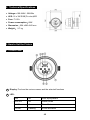
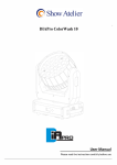
STAGE TRI-PAR 18TC CP-18TC User Manual Please read the instructions carefully before use TABLE OF CONTENTS 1. Safety Instructions 2. Technical Specifications 3. How to Set the Fixture 4. How to Control the Fixture 5. DMX 512 Configuration 6. DMX 512 Connections 7. Troubleshooting 8. Fixture Cleaning 1B 1. Safety Introductions Please read the instructions carefully which includes important information about the installation, operation and maintenance. WARNING Please keep this User Guide for future consultation. If you sell the unit to another user, be sure that they also receive this instruction booklet. All fixtures are intact from the manufacturer, please operate follow up the user manual, artificial fault are not under guarantee repair. Unpack and check carefully that there is no transportation damage before using the unit. The unit is for indoor use only. Use only in a dry location. Do install and operate by operator. Use safety chain when fixes the unit. Don’t handle the unit by taking its head only, but always by taking its base. The unit must be installed in a location with adequate ventilation, at least 50cm from adjacent surfaces. Be sure that no ventilation slots are blocked, otherwise the unit will be overheated. Before operating, ensure that the voltage and frequency of power supply match the power requirements of the unit. It’s important to ground the yellow/green conductor to earth in order to avoid electric shock. Maximum ambient temperature TA : 40℃ . Don’t operate it where the temperature is higher than this. Don’t connect the device to any dimmer pack. First run, there will be smoke or smells, and all disappearing a few minutes later. Make sure there are no flammable materials close to the unit while operating, as it is fire hazard. Look over power wires carefully, replace immediately if there is any damage. Never run on for a long time lest shortening lifespan. Avoid any inflammable liquids, water or metal objects entering the unit. Once it happen, cut off the mains power immediately. Do not operate in dirty and dusty environment, also cleaning fixtures regularly. 2B Do not allow children to operate the fixture. Do not touch any wire during operation as there might be a hazard of electric shock. Avoid power wires together around other cables. Disconnect mains power before fuse/lamp replacement or servicing. Replace fuse only with the same type. In the event of serious operating problem, stop using the unit immediately. Never turn on and off the unit time after time. The housing, the lenses, or the ultraviolet filter must be replaced if they are visibly damaged. Do not open the unit as there are no user serviceable parts inside. Never try to repair the unit by yourself. Repairs carried out by unskilled people can lead to damage or malfunction. Please contact the nearest authorized technical assistance center. Disconnect the mains power if the fixture is not used for a long time. Do use original packing materials once transport it again. Do not look directly at the LED light beam while the fixture is on. For power supply, do not connect in series much more than 7 units, use another mains supply for next 7 units. Installation The unit should be mounted via its screw holes on the bracket. Always ensure that the unit is firmly fixed to avoid vibration and slipping while operating. Always ensure that the structure to which you are attaching the unit is secure and is able to support a weight of 10 times of the unit’s weight. Also always use a safety cable that can hold 12 times of the weight of the unit when installing the fixture. The equipment must be fixed by professionals. And it must be fixed at a place where is out of the touch of people and has no one pass by or under it. 3B 2. Technical Specifications Voltage:100-240V~ 50/60Hz LED: 18 x 3W RGB(Tri-color)LED Fuse: T 6.3A Power consumption:69W Dimension:224 x290 x362 mm Weight: 2.7 kg 3. How to Set the Fixture 3.1 Control Panel 1 ○ Display: To show the various menus and the selected functions 2 ○ LED: DMX On DMX input present MASTER On Master Mode SLAVE On Slave Mode SOUND Flashing Sound activation 4B 3 ○ 4 ○ Button: MENU To select the programming functions DOWN To go backward in the selected functions UP To go forward in the selected functions ENTER To confirm the selected functions Only for remote control: Connecting with CA-8/CA-9/CA-9RTX to control the unit for Stand by, Function and Mode function. 5 ○ DMX output: For DMX512 link, use 3-pin XLR plug cable to link the next unit. 6 ○ DMX input: For DMX512 link, use 3/5-pin XLR plug cable to input DMX signal 7 ○ Mains input: Connect to supply mains power for the unit. 3.2 Main Function To select any functions, press MENU button until the required one is shown on the display. Select the function by ENTER button and the display will blink. Use DOWN and UP button to change the mode. Once the required mode has been selected, press ENTER button to setup or it will automatically return to the main functions without any change after idling one minute. Back to the functions without any change press MENU button. The main functions are shown below: 5B Auto Setting DMX512 Address Show 0-12 Chase MENU Slave Mode 1-16 Sound Mode on Sound Mode off Blackout Mode " Yes Blackout " Blackout Mode " No Blackout " Color Macro LED on LED off Normal Inversion Temperature Fixture Hours Software Version 6B DMX 512 Address Setting Press the MENU button up to when the is shown on the display. Pressing ENTER button and the display will blink. Use DOWN and UP button to change the DMX 512 address. Once the address has been selected, press ENTER button to setup or automatically exit menu mode without any change after one minute. Back to the previous functions without any change press MENU button. Channel Mode Press the MENU button up to when the is shown on the display. Pressing ENTER button and the display will blink. Use DOWN and UP button to select the channels mode) or (4 channels mode) or (4 channels mode) or (4 (4 channels mode) or (6 channels mode)or mode. Once the mode has been selected, press the ENTER button to setup or automatically exit menu mode without any change after one minute. To go back to the functions without any change press the MENU button. Note: In RC8 mode, the fixture will run the effect in RC8 controller. Show Mode Press the MENU button up to when the is shown on the display. Pressing ENTER button, Use DOWN and UP button to select the (show 1) or (Show 2) or … or (Random show) or (show 12), once the show has been selected, press ENTER button to confirm, and use DOWN and UP button to adjust the speed (speed 1) or…or (speed 8). Once the speed has been selected, press the ENTER button to setup or automatically exit menu mode without any change after one minute. To go back to the functions without any change press the MENU button. Chase Mode Press the MENU button up to when the is shown on the display. Pressing ENTER button, Use DOWN and UP button to select the 16) or (chase 1) or…or (chase (fade), once the chase or fade has been selected, press ENTER button to confirm, and use DOWN and UP button to adjust the speed (speed 1) or…or (speed 8). Once the speed has been selected, press the ENTER button to setup or automatically exit menu mode without any change after one minute. To go back to the 7B functions without any change press the MENU button. Slave Mode Press the MENU button up to when the is showing on the display. Pressing ENTER button and the display will blink. Use DOWN and UP button to select the (slave 2) or … or (normal) or (16 light show) mode. Once the mode has been selected, press the ENTER button to setup or automatically return to the main functions without any change after one minute. To go back to the functions without any change press the MENU button again. Sound Press the MENU button up to when the is shown on the display. Pressing ENTER button, Use DOWN and UP button to select the (sound on) or (sound off). Once select, press ENTER button to setup or automatically exit menu mode without any change after one minute. To go back to the functions without any change press the MENU button Blackout mode Press the MENU button up to when the is shown on the display. Pressing ENTER button, Use DOWN and UP button to select the (blackout) or (normal). Once select, press ENTER button to setup or automatically exit menu mode without any change after one minute. To go back to the functions without any change press the MENU button. Color mode Press the MENU button up to when the is shown on the display. Pressing ENTER button, and use DOWN and UP button to select or (color 1) or…or (manual set the color), once you select the confirm, and use DOWN and UP button to select (color 16) , press ENTER button to , or , once the color has been selected, pressing ENTER button to confirm and use DOWN and UP button to adjust the value(0-255), once adjust press ENTER button to setup or automatically exit menu mode without any change after one minute. To go back to the last function without any change press the MENU button. 8B LED display Press the MENU button up to when the is shown on the display. Pressing ENTER button and the display will blink. Use DOWN and UP button to select always on) or (display (display off 20 seconds after exit menu) mode. Once select, press ENTER button to setup or exit menu mode without any change after one minute. Back to the functions without any change press MENU button again. Display Inverse Press MENU button until select is blinking on the display. Use DOWN and UP button to (display normal) or (display inverse), press ENTER button to setup. Back to the functions without any change press MENU button. Temperature Test Press the MENU button up to when the is blinking on the display. Pressing ENTER button and the display will show the temperature of the unit. To go back to the functions press the MENU button again. White Balance Press the MENU button up to when the is shown on the display. Pressing ENTER button, and use DOWN and UP button to select , or , press ENTER button to confirm and use DOWN and UP button to adjust the value between 125 and 255, once select press ENTER button to setup or automatically exit menu mode without any change after one minute. To go back to the last function without any change press the MENU button. Fixture Hours Press the MENU button up to when the is blinking on the display. Pressing ENTER button and the display will show the number of working hours of the unit. To go back to the functions press the MENU button. Software version Press the MENU button up to when the is blinking on the display. Pressing ENTER button and the display will show the version of software of the unit. To go back to 9B the functions press the MENU button again. 4. How to Control the Unit You can operate the unit in three ways: 1. By master/slave built-in preprogram function 2. By easy controller 3. By DMX controller No need to turn the unit off when you change the DMX address, as new DMX address setting will be effected at once. Every time you turn the unit on, it will show “CP21” on the display and move all the motors to their ‘home’ position. After that the unit will be ready to receive DMX signal or run the built in programs. 4.1 Master/Slave Built In Preprogrammed Function The fixture will allow you to link 16 fixtures together and operate without a controller. In Master/Slave mode, the first fixture whose DMX input jack has with nothing connect will be master automatically, set other units to slave 1 or slave2 or … slave 16 via menu, then the first unit will control the others to give an automatic, sound activated, synchronized light show. This function is good when you want an instant show. Any fixture can act as a Master or as a Slave 16-light show In slave mode, slave 1 means the unit works as master, slave 2 means 2-light show, slave 3 means 3-light show and so on, In order to create a great light show, you can set the second unit to slave 2 to get contrast movement to each other, even if you have two units only. 4.2. Easy Controller (by CA-8) The easy remote control is used only in master/slave mode. By connecting to the 1/4” microphone jack of the first unit, you will find that the remote controller on the first unit will control all the other units for Stand by, Function and Mode selection 10B Blackout To blackout all the fixture Function Strobe 1. Synchronous strobe in white color 2. The same color chase 3. Different color strobe Select Color Select show Select Chase Color 1-16 or manual setting color Show 1-12 Chase 1-16 or fade Mode Manual (LED ON) Sound 1 (LED OFF) Sound 2 Auto (LED slow blinking) (LED fast blinking) 4.3 DMX Controller Use universal DMX controller to control the units, you have to set DMX address from 1 to 512 channel so that the units can receive DMX signal. Press the MENU button up to when the is showing on the display. Pressing ENTER button and the display will blink. Use DOWN and UP button to change the DMX512 address. Once the address has been selected, press and keep ENTER button pressed up to when the display stops blinking or storing automatically one minute later. To go back to the functions without any change press the MENU button again. If you use please refer to the following diagram to address your DMX512 channel for the first 4 units. 4 channels: 6 channels: 11B 5. DMX512 Configuration Mode 1&2; DMX512 Configuration Mode1 Mode2 CH 1 CH2 CH3 CH4 CH 1 CH2 CH3 CH4 Red Green Blue Dimmer/Strobe Red Green Blue Dimmer 248-255 Open Fast 201-247 Slow 191-200 Sound 8-190 0-7 Off Mode 3&4: DMX512 Configuration Mode3 Mode4 CH 1 CH2 CH3 CH4 CH 1 CH2 CH3 CH4 Red Green Blue Dimmer/Strobe Red Green Blue Dimmer Slow 200-255 Color 161-255 Fast Macro Fast Fast Slow 128-199 Slow 0-160 0-127 12B Mode 5: DMX512 Configuration Mode5 CH 1 CH2 CH3 Red Green Blue CH4 Dimmer Ch5 Ch6 Color Strobe 248-255 Color32 241-247 Color31 233-240 Color30 225-232 Color29 217-224 Color28 248-255 Open 210-216 Color27 202-209 Color26 240-247 Random strobe 194-201 Color25 186-193 Color24 232-239 Open 179-185 Color23 Slow Close 171-178 Color22 163-170 Color21 191-231 Fast Open 155-162 Color20 148-154 Color19 182-190 Open 140-147 Color18 132-139 Color17 140-181 Slow Open Fast Close 124-131 Color16 117-123 Color15 109-116 Color14 132-139 Open 101-108 Color13 093-100 Color12 086-092 Color11 16-131 078-085 Color10 070-077 Color9 062-069 Color8 055-061 Color7 047-054 Color6 8-15 Open 039-046 Color5 031-038 Color4 024-030 Color3 0-7 Off 016-023 Color2 008-015 Color1 000-007 OFF 6. DMX512 Connections The DMX512 is widely used in intelligent lighting control, with a maximum of 512 channels. 13B 1. Connect the fixture together in a “daisy chain” by XLR plug cable from the output of the fixture to the input of the next fixture. The cable cannot be branched or split to a “Y” cable. Inadequate or damaged cables, soldered joints or corroded connectors can easily distort the signal and shut down the system 2. The DMX output and input connectors are pass-through to maintain the DMX circuit when one of the units’ power is disconnected. 3. At last fixture, the DMX cable has to be terminated with a terminator to reduce signal errors. Solder a 120-ohm 1/4W resistor between pin 2(DMX-) and pin 3(DMX+) into a 3-pin XLR-plug and plug it in the DMX-output of the last fixture. 4. Each lighting fixture needs to have an address set to receive the data sent by the controller. The address number is between 0-511 (usually 0 & 1 are equal to 1). 5. 3 pin XLR connectors are more popular than 5 pins XLR. 3 pin XLR: Pin 1: GND, Pin 2: Negative signal (-), Pin 3: Positive signal (+) 5 pin XLR: Pin 1: GND, Pin 2: Negative signal (-), Pin 3: Positive signal (+), Pin4/5: not used 7. Troubleshooting Following are a few common problems that may occur during operation. Here are some suggestions for easy troubleshooting: A. The fixture does not work, no light 1. Check the connection of power and main fuse. 2. Measure the mains voltage on the main connector. B. Not responding to DMX controller 1. DMX LED should be on. If not, check DMX connectors, cables to see if link properly. 2. If the DMX LED is on and no response to the channel, check the address settings and 14B DMX polarity. 3. If you have intermittent DMX signal problems, check the pins on connectors or on PCB of the fixture or the previous one. 4. Try to use another DMX controller. 5. Check if the DMX cables run near or run alongside to high voltage cables that may cause damage or interference to DMX interface circuit. C. Some fixtures don’t respond to the easy controller 1. You may have a break in the DMX cabling. Check the LED for the response of the master/ slave mode signal. 2. Wrong DMX address in the fixture. Set the proper address. D. No response to the sound 1. Make sure the fixture does not receive DMX signal. 2. Check microphone to see if it is good by tapping the microphone. E. One of the channels is not working well 1. The stepper motor might be damaged or the cable connected to the PCB is broken. 2. The motor’s drive IC on the PCB might be out of condition. 8. Fixture Cleaning The cleaning of internal must be carried out periodically to optimize light output. Cleaning frequency depends on the environment in which the fixture operates: damp, smoky or particularly dirty surrounding can cause greater accumulation of dirt on the fixture’s optics. Clean with soft cloth using normal glass cleaning fluid. Always dry the parts carefully. Clean the external optics at least every 20 days. Clean the internal optics at least every 30/60 days. Innovation, Quality, Performance 15B