1
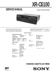
XR-4880
SERVICE MANUAL
AEP Model
UK Model
Photo: XR-4880
Model Name Using Similar Mechanism
XR-C6100R
Tape Transport Mechanism Type
MG-25F-136
SPECIFICATIONS
FM/MW/LW CASSETTE CAR STEREO
MICROFILM
SECTION 6
DIAGRAMS
• IC Block Diagrams – MAIN Board –
AM CP OUT
VT
FM CP OUT
D-GND
AM IN
IFC
22 21
20
19
18
17
16 15 14 13
IN1 3
+
AMP
VDD
FM IN
VCC
24 23
IC351
VCC 1
NC 2
REG
A-GND
XI
IC21 TB2118F (EL)
10 NC
BUFFER
MOTOR
DRIVE
CIRCUIT
CONTROL
CIRCUIT
IN2 4
VDD
VCC
9 OUT1
8 NC
7 OUT2
BUFFER
– +
AMP
– +
4BIT SWALLOW
COUNTER
REGULATOR
SEEK/RECP
SEEK/RECP
SIG
6 P-GND
S-GND 5
AMP
+
PRESCALLER
PHASE
COMPARATOR
12BIT
PROGRAMMABLE
COUNTER
REF
20BIT
IF COUNTER
40BIT SHIFT
REGISTER
REFERENCE
DIVIDER
OSCILLATOR
LB1930M-TLM
18BIT
22BIT
18BIT
ON/OFF
IC331
3 4 5 6
7
8
9
10 11
12
I/O-1
I/O-2
OUT-1
VDD2
OUT-2
2
SR
OUTPUT
PORT
CE
DIN
CK
DOUT
XO
1
I/O
PORT
OSC
SERIAL
INTERFACE
VDD2
BUFFER
TDA7462D
28
27
26
25
24
23
FRONT SIDE
SELECTOR
1
2
3
4
5
6
7
8
9
10
11
12
13
INPUT
GAIN &
AUTO
ZERO
LOUDNESS
CONTROL
CIRCUIT
VOLUME
CONTROL
CIRCUIT
SOFT
MUTE
TREBLE/
BASS
CONTROL
CIRCUIT
VOICE BANDPASS
HP
FRONT
FADER
22 OUT FL
FRONT
FADER
21 OUT FR
REAR
FADER
20 OUT RL
REAR
FADER
19 OUT RR
LP
COMPANDER
REAR SIDE
SELECTOR
SE1L
SE1R
MD+
MD–
CDL+
CDL–
CDR–
CDR+
PDR
PDGND
PDL
SE2L
SE2R
INPUT MULTIPLEXER &
MIXING STAGE
PAUSE
DETECT
SE3L
SE3R
MUTE
SDA
SCL
PAUSE
INPUT
GAIN
LOUDNESS
CONTROL
CIRCUIT
SUBWOOFER
LP
BEEP
FADER
18 SUBOUT+
SUBWOOFER
OUT
17 SUBOUT–
SDA
DIGITAL CONTROL CIRCUIT
IIC
BUS
SCL
POWER
SUPPLY
CREF 14
– 17 –
16 VDD
15 GND
– 21 –
A (OFF) → B (ON)
(Page 23, 24)
(FL)
– 22 –
–
(Page 27)
– 24 –
Note on Schematic Diagram:
• All capacitors are in µF unless otherwise noted. pF: µµF
50 WV or less are not indicated except for electrolytics
and tantalums.
• All resistors are in Ω and 1/4 W or less unless otherwise
specified.
¢
: internal component.
•
• C : panel designation.
• U : B+ Line.
• Power voltage is dc 14.4V and fed with regulated dc power
supply from ACC and BATT cords.
• Voltage and waveforms are dc with respect to ground
under no-signal conditions.
no mark : FM
<
> : TAPE PLAYBACK
: Impossible to measure
∗
• Voltages are taken with a VOM (Input impedance 10 MΩ).
Voltage variations may be noted due to normal production
tolerances.
• Waveforms are taken with a oscilloscope.
Voltage variations may be noted due to normal production
tolerances.
• Circled numbers refer to waveforms.
• Signal path.
F : FM
f : AM (MW)
E : TAPE PLAYBACK
age is dc 14.4V and fed with regulated dc power
m ACC and BATT cords.
nd waveforms are dc with respect to ground
ignal conditions.
FM
TAPE PLAYBACK
mpossible to measure
e taken with a VOM (Input impedance 10 MΩ).
ations may be noted due to normal production tol-
–
• Waveforms are taken with a oscilloscope.
Voltage variations may be noted due to normal production tolerances.
• Circled numbers refer to waveforms.
• Signal path.
F : FM
f : AM (MW)
E : TAPE PLAYBACK
– 28 –
6-6. IC PIN FUNCTION DESCRIPTION
• IC501 MASTER U-COM (MN101C12GTC1)
Pin No.
1
Pin Name
VREF-
I/O
–
Function
Basic voltage (- side) of AD conversion input
2
VSM
I
FM/AM common signal meter A/D conversion input terminal
3
KEYIN1
I
4
KEYIN0
I
5
DBASS IN
I
Position detecting AD input terminal of D-BASS
6
DSTSEL
I
Terminal for setting to select the value of destination
7
FUNC-SEL
I
Function selecting (AD conversion) input
8
–
O
Not used
KEY (AD conversion) input
9
RC-IN0
I
Rotary commander (AD conversion) input
10
VREF+
I
Basic voltage (+side) of AD conversion input
11
VDD
–
Power supply
12
OSC2
–
13
OSC1
–
Radiator (18.432 MHz) connecting terminal
14
VSS
–
15
XI
–
Ground
16
XO
–
17
MMOD GND
–
Ground
18
RC-IN1
I
Rotary commander shift input
19
SYSRST
O
SYSTEM RESET control output
20
BUSON
O
BUS ON control output
21
UNISO
O
Serial data output
22
UNISI
I
Serial data input
23
UNICKO
O
Serial clock output
24
UNICKI
I
Serial clock input
25
–
O
Not used
26
KEYACK
I
Key input acknowledge
Sub clock (for clock) radiator (32 kHz) connecting terminal
27
NOSESW
I
Removing/attaching front panel detection input
28
BU-IN
I
BACK-UP detection input terminal
29
SIRCS
I
Remote control input
30
TELMUT
I
TELEPHONE MUTE detection input
31
TEST-IN
I
Test mode setting input terminal
32
RAMBU
I
Reset detection input of RAM
33
RESET
I
Reset input terminal
34
VOL-MUT
O
Electrical volume mute control output
35
BEEP
O
Control output for buzzer
36
AMPMUT
O
Power amplifier mute control output terminal
37
AMPON
O
Power amplifier STANDBY control terminal
38
PLL-CKD
O
PLL CLK output terminal
39
PLL-CE
O
PLL CE output terminal
40
PLL-SO
O
PLL DATA output terminal
41
PLL-SI
I
PLL DATA input terminal
42
LCD-SO
O
LCD serial data output
43
LCD-CE
O
LCD chip enable output terminal
44
LCD-CKO
O
LCD serial clock output
45
VOL-SIO
O
Electrical volume serial data output
46
–
O
Not used
47
VOL-CKD
O
Electrical volume serial data output
48
ACC-IN
I
Accessory power supply detection input
49
MUT
O
System MUTE control output
– 29 –
Pin No.
Pin Name
I/O
Function
50
NCO
O
Not used
51
AMSON
O
“L” is output in AMS mode
52
N/R-OUT
O
FWD/REV control output
53
MTLON
I/O
Metal control input/output
54
TAPMUT
O
55
DOLON
I/O
56
57 to 75
Tape mute control output
Dolby control input/output
AMSIN
I
Input to detect existence of song during AMS mode
NCO
O
Not used
76
ST
77
SD-IN
I/O
I
78
REIN 1
I
79
REIN 0
I
80
AD ON
O
Power supply control output of AD conversion
81
PW SEL
I
Power selection initialise
82
ILLON
O
Illumination power supply control output
Input to detect rotation of reel table
83
REL
I
84
POS3
I
85
POS2
I
86
POS0
I
87
POS1
I
88
LM LOD
O
89
LM EJ
O
Combination stereo input and monaural output
SIGNAL DETECTOR input terminal
Rotary encoder input terminal
Tape position signal detection input
Loading motor control output (to a direction of loading)
Loading motor control output (to a direction of ejection)
TAPE power supply control output
90
TAPON
O
91
CM ON
O
Capstan motor control signal output terminal of TAPE
92
PW ON
O
System power supply control output
93
FM ON
O
FM power supply control output terminal
94
TUNON
O
TUNER power supply control output terminal
95
96 to 99
100
When ‘on’ is output, “H” is output, otherwise when ‘off’ is output, “L” is output.
DAVSS
–
Ground
NCO
O
Not used
DAVDD
–
Not used (Power supply for DA converter)
– 30 –
This datasheet has been downloaded from:
www.EEworld.com.cn
Free Download
Daily Updated Database
100% Free Datasheet Search Site
100% Free IC Replacement Search Site
Convenient Electronic Dictionary
Fast Search System
www.EEworld.com.cn
All Datasheets Cannot Be Modified Without Permission
Copyright © Each Manufacturing Company