1
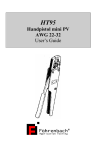
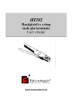
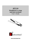
HT250
Handpistol for Dubox
AWG 22-24
User’s guide
www.foehrenbach.be
CONTENTS
1. DESCRIPTION ..................................................................................................3
2. OPERATING INSTRUCTIONS ..........................................................................3
3. ADJUSTMENTS ................................................................................................4
4. MAINTENANCE.................................................................................................5
5. PARTS...............................................................................................................7
6. COMPANY ADDRESS ......................................................................................10
CERTIFICATE OF CONFORMITY..........................................................................11
Instruction manual HT250
Date : August 2007
Documentrev. : 6
www.foehrenbach.be
Page : 2 / 11
1. DESCRIPTION
The handtool HT 250 is designed to crimp Dubox terminals with small reel in the wire range
AWG 22-24.
The terminals are guided in a feed track, fed with hand (yellow lever), positioned in crimp
tooling and crimped. During the crimp action the Dubox terminal is cut off from the carrier strip.
2. OPERATING INSTRUCTIONS
1.
Place the handtool in your left hand, so that the movable handle (item 11 , figure 1) may
be actuated by your thumb.
Actuate with the right hand the yellow lever (item 6 , figure 2) which feeds the Dubox
terminal into the crimping area.
Use wire which is stripped over a length of 2.75 ± 0.25 mm.
Place the wire into the barrel of the terminal so that the end of the wire touches the wire
stop.
Close the handtool by moving the mobil handle while the wire is held in position.
When
the
handtool
is
completely
closed,
the
movable
handle
(item 11 , figure 1) may be returned to its starting position.
Finally take the crimped terminal from the handtool.
2.
3.
4.
5.
6.
7.
Note:
The handtool has stops, which prevents opening the tool before the crimp action is
completed. Should it be necessary, the stop can be released by turning the ratchet wheel at
the back of the tool in the direction indicated by the two yellow arrows. Keep the movable
handle under light pressure during this operation.
Instruction manual HT250
Date : August 2007
Documentrev. : 6
www.foehrenbach.be
Page : 3 / 11
3. ADJUSTMENTS
Adjustments of crimp height:
Eventually, the tool hinges can wear, so that the crimp height must be readjusted (see
below specified height).
This is done by loosening the screw (item 21 , figure 1) and rotating the stop rings
(item 20 , figure 1) one stop to change the crimp height approximately 0.05 mm (0.002
inches).
Adjustment of feed track unit (see figure 2)
CAUTION: No adjustments should be made with screw (item 21, fig 1), nut (item 22,
fig 1) and with screw (item 23, fig 1).
Adjustment of feeding:
Loosen screws (item 13, fig 2) and turn screw (item 27, fig 2) to the left for further
feeding of terminal and to the right for less feeding. The fed terminal must lay above
the anvil. Tighten screw (item 13, fig 2) after adjustment.
Adjustment of cutter plate:
Loosen screws (item 18, fig 2) and place cutter plate (item 19, fig 2) against the anvil.
Tighten screws (item 18, fig 2) after adjustment.
Note:1) During adjustment handtool must be in closed position.
2) When closing handtool (without terminal), the cutter plate may not move up.
Adjustment of terminal position:
Loosen screws (item 18, fig 2) and adjust terminal positioner (item 17, fig 2) so that the
feed finger locates the terminals through the pilot holes. Tighten screws (item 18, fig 2)
after adjustment.
Note: 1) The terminal positioner may not damage the insulation barrel or wire barrel
of terminal.
2) This adjustment may affect the bellmouth of the terminal.
Instruction manual HT250
Date : August 2007
Documentrev. : 6
www.foehrenbach.be
Page : 4 / 11
4. MAINTENANCE
•
•
•
Regular checks must be made for possible gold build-up on crimper and anvil.
If necessary, these parts may be cleaned.
Damaged parts must be replaced immediately. For part numbers see parts list.
Attention!
- Apply the tool only for the purpose as mentioned in chapter 1.
- Apply the tool only in a dry and well illuminated environment (1000 lux).
- Apply always a correct eye protection.
Instruction manual HT250
Date : August 2007
Documentrev. : 6
www.foehrenbach.be
Page : 5 / 11
Figure 1
Instruction manual HT250
Date : August 2007
Documentrev. : 6
www.foehrenbach.be
Page : 6 / 11
5. PARTS
Parts for figure 1
item no
1
2
3
4
5
6
7
8
9
10
11
12
13
14
15
16
17
18
19
20
21
22
23
24
26
27
28
29
35
37
38
39
40
41
42
43
44
45
part No
description
180998
5315-001-002
172391
172392
180999
172397
181000
181001
181002
181003
181004
181005
172388
190583
181006
172394 A
181007
5315-001-009
5305-003-006
190582
5305-003-050
191623
5305-003-009
180699
5315-001-008
5305-004-008
181008
5305-001-017
5305-003-009
181009
181010
191607
191608
5310-001-006
191609
5305-035-003
191610
5305-003-008
Housing
Dowel pin ø 2 x 9,7
Pawl
Extension spring No 19
Handle, permanent
Connecting pin
Spacer plate
Retainer
Retainer coverplate
Connecting plate
Handle, mobile
Shaft
Hinge pin
Stop roll
Eccentric pin
Extension spring No 35
Cover plate
Dowel pin ø 3m6 x 12
But. hd. cap screw M4 x 7
Stopring
But. hd. cap screw M3 x 4
Feeding stop
But. hd. cap screw M4 x 16
Crimp unit
Dowel pin ø 3m6 x 10
Hex. soc. c’sink hd screw M4 x 10
Guiding block
Soc. hd. cap screw M3 x 12
But. hd.cap screw M4 x 14
Bushing ø 6
Bushing ø 8
Reelbracket
Rod end M6
Hex nut M6 Din 934
Compression spring No 59
Waher 6,0 Din 1440
Special nut M6
But. hd. cap screw M4 x 12
Instruction manual HT250
Date : August 2007
Documentrev. : 6
qty per
assy
1
1
1
1
1
2
1
1
1
2
1
1
1
1
1
1
1
1
4
1
1
1
1
1
2
1
1
1
1
1
1
1
1
1
1
1
1
2
www.foehrenbach.be
Page : 7 / 11
46
48
49
50
51
52
53
Plastic grip
Washer ø 4,2 x 12 x 1,5
Nut M4 Din 985
Pin ø2 x 7,2
Stop
Washer ø 3,2 x 7
But. hd. cap screw M3 x 10
2
4
2
1
1
1
1
part No
description
181014
191591
191592
191593
191594
181015
181016
191597
181017
191599
191600
181018
5305-003-051
181019
181020
191604
181021
5305-003-050
181022
191614
5305-007-013
5310-002-002
5305-007-010
5305-003-051
181023
5305-007-010
5305-007-062
180983
180984
Feed track
Distance plate
Stop pin
Washer φ 4.2x12x1.5
Feed finger pivot
Feed lever
Rond end M3
Compression spring
Feed finger
Jaw finger spring No 60
Stop screw
Terminal guide
Button head cap screw M4x5
Feed track cover
Compression spring No 129
Spring holder screw
Terminal positioner
Button head cap screw M3x4
Cutter plate
Carrier strip guiding plate
Socket set screw M4x15
Hexagonal nut M4 DIN 934
Socket set screw M4x8 Din916
Button head cap screw M4x6
Knurled screw M4 x 16 Din 653
Socket set screw M4x8
Socket set screw M4x20
Stop bushing
Distance plate
qty per
assy
1
2
1
5
1
1
1
1
1
1
1
1
3
1
2
2
1
4
1
1
1
1
1
2
190115
190116
190117
Key for crimp height adjustment
Upper pin wrench 2 mm
Pin wrench 2.5 mm
181011
191593
181012
172393
181013
5310-007-003
5305-003-003
Parts for figure 2
item no
1
2
3
4
5
6
7
8
9
10
11
12
13
14
15
16
17
18
19
20
21
22
23
24
25
26
27
28
29
Instruction manual HT250
Date : August 2007
Documentrev. : 6
1
1
1
1
1
1
1
www.foehrenbach.be
Page : 8 / 11
Figure 2
Instruction manual HT250
Date : August 2007
Documentrev. : 6
www.foehrenbach.be
Page : 9 / 11
6. CONTACT
Föhrenbach Application Tooling
Krijgsbaan 128
2640 Mortsel
Belgium
E-mail : [email protected]
URL: www.foehrenbach.be
The technical data in this publication has been carefully checked and assembled. No liability from inaccuracies or errors is assumed. The right to change or
improve this document without notice is reserved.
Instruction manual HT250
Date : August 2007
Documentrev. : 6
www.foehrenbach.be
Page : 10 / 11
CERTIFICATE OF CONFORMITY
We hereby certify that the hand tool HT250 described below has been manufactured and
inspected, and is conform to applicable drawings, requirements and specifications, according
to FCI spec TA-317.
Serial number of hand tool:
………………………..
Specification:
•
Wire range AWG 22-24: 0.22 - 0.33 mm²
•
Crimp height
0.83 – 0.89 mm
.0325 - .0350 inches
Adjusted crimp height by manufacturer: ………… mm
Instruction manual HT250
Date : August 2007
Documentrev. : 6
www.foehrenbach.be
Page : 11 / 11